Note: Descriptions are shown in the official language in which they were submitted.
TEMPERATURE CONTROLLED STORAGE SYSTEM
The present invention relates to stacked, grid storage systems especially
densely
packed storage systems and methods of adjusting, regulating, controlling and
maintaining the temperature of said storage systems.
This application claims priority from UK Patent Application Nos. GB1509661.3
filed on 3rd June 2015 and GB1604096.6 filed on 10th March 2016.
Some commercial and industrial activities require systems that enable the
storage and retrieval of a large number of different products. One known type
of
system for the storage and retrieval of items in multiple product lines
involves
arranging storage bins or containers in stacks on top of one another, the
stacks
being arranged in rows. The storage bins or containers are accessed from
above, removing the need for aisles between the rows and allowing more
containers to be stored in a given space.
Methods of handling containers stacked in rows have been well known for
decades. In some such systems, for example as described in US 2,701,065, to
Bertel comprise free-standing stacks of containers arranged in rows in order
to
reduce the storage volume associated with storing such containers but yet
still
providing access to a specific container if required. Access to a given
container
is made possible by providing relatively complicated hoisting mechanisms which
can be used to stack and remove given containers from stacks. The cost of such
systems are, however, impractical in many situations and they have mainly been
commercialised for the storage and handling of large shipping containers.
The concept of using freestanding stacks of containers and providing a
mechanism to retrieve and store specific containers has been developed
further,
for example as described in EP 0 767 113 B to Cimcorp. '113 discloses a
mechanism for removing a plurality of stacked containers, using a robotic load
handler in the form of a rectangular tube which is lowered around the stack of
containers, and which is configured to be able to grip a container at any
level in
the stack. In this way, several containers can be lifted at once from a stack.
The
1
Date recue / Date received 2021-10-29
movable tube can be used to move several containers from the top of one stack
to the top of another stack, or to move containers from a stack to an external
location and vice versa. Such systems can be particularly useful where all of
the
containers in a single stack contain the same product (known as a single-
product
stack).
In the system described in '113, the height of the tube has to be at least as
high
as the height of the largest stack of containers, so that the highest stack of
containers can be extracted in a single operation. Accordingly, when used in
an
enclosed space such as a warehouse, the maximum height of the stacks is
restricted by the need to accommodate the tube of the load handler.
EP 1037828 B1 (Autostore)
describes a system in which stacks of containers are arranged within a
frame structure. A system of this type is illustrated schematically in Figures
1 to 4
of the accompanying drawings.
Robotic load handling devices can be
controllably moved around the stack on a system of tracks on the upper most
surface of the stack.
It is a disadvantage of the prior art systems described above that the
temperature
within densely packed stacks is difficult to accurately regulate.
According to the invention there is provided an object handling system
comprising
two substantially perpendicular sets of rails forming a grid above a
workspace,
the workspace comprising a plurality of stacked containers, the handling
system
further comprising a plurality of robotic load handling devices operating on
the
grid above the workspace, the load handling devices comprising a body mounted
on wheels, a first set of wheels being arranged to engage with at least two
rails of
the first set of rails, the second set of wheels being arranged to engage with
at
least two rails of the second set of rails, the first set of wheels being
independently moveable and driveable with respect to the second set of wheels
such that when in motion only one set of wheels is engaged with the grid at
any
one time thereby enabling movement of the load handling device along the rails
to any point on the grid by driving only the set of wheels engaged with the
rails,
the system further comprising one or more heater and/or one or more chiller
for
2
Date recue / Date received 2021-10-29
CA 02988019 2017-12-01
WO 2016/193419 PCT/EP2016/062632
generating temperature controlled gas, one or more fan for circulating the
temperature controlled gas through the storage system; and a plenum for
receiving the temperature controlled gas.
In a preferred aspect the plenum has an opening adjacent a side of the grid of
storage stacks.
In a preferred aspect in use the storage system generates a reservoir of
temperature controlled gas in the storage system.
In a preferred aspect the reservoir of temperature controlled gas forms above
the
storage stacks.
In a preferred aspect the temperature controlled gas circulates around, under,
over or through the storage container stacks.
In a preferred aspect the temperature of the storage system can be varied from
-
30 C to +30 C.
In a preferred aspect the temperature of the storage system can be controlled
within a range of 2.5 C.
In a preferred aspect the temperature controlled gas is circulated through one
or
more apertures in the storage containers.
In a preferred aspect temperature controlled fluid is circulated through
ducting.
In a preferred aspect the ducting runs through the walls and uprights and
frame
work structure of the grid.
In a preferred aspect the gas is air.
In a preferred aspect the gas is a coolant gas.
In a further aspect the invention relates to a storage container having one or
more
apertures in one or more sides.
In a preferred aspect the storage container further comprises ducting for
receiving
the temperature controlled fluid.
3
CA 02988019 2017-12-01
WO 2016/193419 PCT/EP2016/062632
In this way, the present invention overcomes the problems of the prior art and
provides a storage system capable of accurately maintaining and varying the
temperature within a stacked grid storage system
The invention will now be described with reference to the accompanying
diagrammatic drawings in which:
Figure 1: is a schematic perspective view of a frame structure for housing a
plurality of stacks of bins in a known storage system;
Figure 2: is a schematic plan view of part of the frame structure of Figure 1;
Figures 3a and 3b: are schematic perspective views, from the rear and front
respectively, of one form of robotic load handling device for use with the
frame
structure of Figures 1 and 2, and Figure 3c is a schematic perspective view of
the
known load handler device in use lifting a bin;
Figure 4: is a schematic perspective view of a known storage system comprising
a plurality of load handler devices of the type shown in Figures 3a, 3b and 3c
installed on the frame structure of Figures 1 and 2, together with a robotic
service
device;
Figures 5a and 5b: are schematic perspective views of two forms of container
which form a major component of the storage system of the present invention;
Figure 6a: is a side elevation of one embodiment of the storage system
according
to the present invention comprising multiple stacks showing the air movement
within said storage system.
Figure 6b: is a side elevation of a second embodiment of the storage system
according to the present invention comprising multiple stacks and showing the
air
movement within said storage system.
Figure 7a: is a schematic perspective view of the storage system shown in
Figure
6a showing the arrangement of the stacks in a grid the chiller units 12 and
the
fans 10.
4
CA 02988019 2017-12-01
WO 2016/193419 PCT/EP2016/062632
Figure 7b: is a schematic perspective view of the storage system shown in
Figure
6a showing the plenum.
Figure 8: is a side elevation of an alternative embodiment of the storage
system
showing the chillers 12 set back from the plenums 14.
Figure 9: is a side elevation of an alternative embodiment of the storage
system
showing the fans 10 located on a vertical side of the plenums 14.
Figure 10: is a plan view of the storage system shown in Figure 6a
Figure 11: is a plan view of an alternative embodiment of the storage system
in
which the stacks are of different widths showing how the plenum follows the
edge
of the grid storage system.
Figure 12: is a side elevation of another embodiment of the storage system in
which a number of empty rows 24 are located within the grid of stacks.
Figure 13: is a side elevation of another embodiment of the storage system in
which the stacks are raised above the floor showing air being drawn through
the
system and into the vacant space under the stacks.
Figure 14: a side elevation of another embodiment of the storage system on a
mezzanine floor above ground level 32 showing the movement of air through
vertical ducting 30 and horizontal ducting 28.
Figure 15a and 15b: are schematic perspective views of another embodiment of
the storage system in which storage containers having additional and larger
apertures 34 are used on the bottom level of each stack to allow greater air
flow.
Figure 16a, 16b: are schematic perspective views of another embodiment of the
storage system in which ducting 36 runs through the storage containers to
increase air flow.
Figures 17a and 17b: are schematic perspective views of another embodiment of
the storage system in which tubes 40 are provided in the walls of the grid to
assist air circulation between the storage stacks.
5
CA 02988019 2017-12-01
WO 2016/193419 PCT/EP2016/062632
As used herein the term plenum is a space or chamber for receiving
heated or cooled air.
As shown in Figures 1 and 2, stackable containers, known as bins 10, are
stacked on top of one another to form stacks 12. The stacks 12 are arranged in
a
grid frame structure 14 in a warehousing or manufacturing environment. Figure
1
is a schematic perspective view of the frame structure 14, and Figure 2 is a
top-
down view showing a single stack 12 of bins 10 arranged within the frame
structure 14. Each bin 10 typically holds a plurality of product items (not
shown),
and the product items within a bin 10 may be identical, or may be of different
product types depending on the application.
The frame structure 14 comprises a plurality of upright members 16 that
support
horizontal members 18, 20. A first set of parallel horizontal members 18 is
arranged perpendicularly to a second set of parallel horizontal members 20 to
form a plurality of horizontal grid structures supported by the upright
members 16.
The members 16, 18, 20 are typically manufactured from metal. The bins 10 are
stacked between the members 16, 18, 20 of the frame structure 14, so that the
frame structure 14 guards against horizontal movement of the stacks 12 of bins
10, and guides vertical movement of the bins 10.
The top level of the frame structure 14 includes rails 22 arranged in a grid
pattern
across the top of the stacks 12. Referring additionally to Figures 3 and 4,
the rails
22 support a plurality of robotic load handling devices 30. A first set 22a of
parallel rails 22 guide movement of the load handling devices 30 in a first
direction (X) across the top of the frame structure 14, and a second set 22b
of
parallel rails 22, arranged perpendicular to the first set 22a, guide movement
of
the load handling devices 30 in a second direction (Y), perpendicular to the
first
direction. In this way, the rails 22 allow movement of the load handling
devices 30
in two dimensions in the X-Y plane, so that a load handling device can be
moved
into position above any of the stacks 12.
Each load handling device 30 comprises a vehicle 32 which is arranged to
travel
in the X and Y directions on the rails 22 of the frame structure 14, above the
stacks 12. A first set of wheels 34, consisting of a pair of wheels 34 on the
front of
6
CA 02988019 2017-12-01
WO 2016/193419 PCT/EP2016/062632
the vehicle 32 and a pair of wheels 34 on the back of the vehicle 32, are
arranged
to engage with two adjacent rails of the first set 22a of rails 22. Similarly,
a
second set of wheels 36, consisting of a pair of wheels 36 on each side of the
vehicle 32, are arranged to engage with two adjacent rails of the second set
22b
of rails 22. Each set of wheels 34, 36 can be lifted and lowered, so that
either the
first set of wheels 34 or the second set of wheels 36 is engaged with the
respective set of rails 22a, 22b at any one time.
When the first set of wheels 34 is engaged with the first set of rails 22a and
the
second set of wheels 36 are lifted clear from the rails 22, the wheels 34 can
be
driven, by way of a 20 drive mechanism (not shown) housed in the vehicle 32,
to
move the load handling device 30 in the X direction. To move the load handling
device 30 in the Y direction, the first set of wheels 34 are lifted clear of
the rails
22, and the second set of wheels 36 are lowered into engagement with the
second set of rails 22a. The drive mechanism can then be used to drive the
second set of wheels 36 to achieve movement in the Y direction.
In this way, one or more robotic load handling devices 30 can move around the
top surface of the stacks 12 on the frame structure 14 under the control of a
central picking system (not shown). Each robotic load handling device 30 is
provided with means for lifting out one or more bins or containers from the
stack
to access the required products. In this way, multiple products can be
accessed
from multiple locations in the grid and stacks at any one time.
It will be noted from the description above and with reference to the
drawings,
that the portion of the load handling device 30 carried by the wheels covers
one
grid spacing of the grid system above the stack.
Figure 4 shows a typical storage system as described above, the system having
a plurality of load handling devices 30 active on the stacks 12.
With reference to Figure 5 the storage system of the present invention
comprises
a series of storage bins or containers 1 stacked one on top of another to form
a
storage stack 12.
7
CA 02988019 2017-12-01
WO 2016/193419 PCT/EP2016/062632
As shown in Figure 5 each storage container may have one or more aperture 50
in one or more side to allow air to circulate freely through the storage
container.
This container can vary in shape and size.
The apertures are shaped and sized such that they do not undermine the
strength or structural integrity of the storage container. Preferably between
5 %
and 20 % of the surface area of the side of the storage container should be
open
in the form of apertures to allow air flow through the container. Apertures
may be
provided in 2,3,4,5 or 6 sides of the container.
As shown in Figure 6a a plurality of stacks are arranged in a grid frame
structure
8 to form a high density grid storage system.
One or more chiller units 12 are located above the storage stacks and form a
reservoir 6 of cooled air above the storage stacks. As shown by the arrows in
Figures 6a and 6b the cooled air moves between, around and through the
storage stacks and enters a plenum 14.
The plenum 14 comprises a channel of height 20 and width 22. The width 22 of
the plenum 14 can vary from 1 m to 4 m. The height of the plenum 20 can vary
from the same height as the storage system to 2 m below the top of the storage
system.
The plenum is sealed on three sides. The plenum has an opening adjacent the
storage stacks.
As shown in Figures 7a and 7b the plenum 14 is located along one or more side
of the grid of stacks.
One or more fans 10 are located either on the top of the plenum 14 as shown in
Figure 6 or on the vertical face of the plenum as shown in Figure 9.
The one or more fans 10 helps to circulate the cooled air from the reservoir 6
through around, and between the storage stacks to the plenum 14
As the cooled air circulates through the storage system it adjusts the
temperature
of the storage stacks and their contents.
8
CA 02988019 2017-12-01
WO 2016/193419 PCT/EP2016/062632
The chiller units 12 units can be located either directly above the plenums as
shown in Figure 6 or they can be set back as shown in Figure 8. The key
requirement is that a reservoir of cooled air 6 is created above the storage
system.
The number, size and location of chiller units will vary depending on the size
of
the storage system.
The width of the storage system 18 can vary from 15 m to 80 m, however, it
will
be appreciated that any width of storage system may be envisaged with suitable
adjustments to the equipment required.
The length 21 of the storage system has no upper limit. Multiple plenums,
fans,
and chillers can be positioned periodically along the entire length of the
storage
system to achieve the desired level of temperature control.
The height 25 of the system can be up to 7.8 m high.
The power and number of fans 10 depends on the size of the system with
diameter of the fans varying from 0.5 m to 2.5 m.
In an alternative embodiment the chillers 12 may be replaced with heaters
which
form a reservoir 6 of heated air.
In an alternative embodiment the chiller units may be supplemented by heater
units. The reservoir 6 is then one of temperature controlled air.
In an alternative embodiment the reservoir 6 may be formed under the storage
stacks.
In an alternative embodiment a gas other than air e.g. a coolant may be
circulated in the storage system to better assist temperature regulation.
In an alternative embodiment the chillers 12 may be replaced with heaters
which
form a reservoir of heated air above the storage stacks.
The temperature of the storage system can be controlled within a range of
2.5 C.
9
CA 02988019 2017-12-01
WO 2016/193419 PCT/EP2016/062632
The temperature within the storage system can be varied from -30 C to +30 C.
Referring to Figure 11 which is a plan view of an alternative embodiment of a
storage system of the present invention in which the stacks within the grid
storage system are of different widths. The plenum follows the edge of the
storage system grid even as the width of the grid changes.
The plenum does not need to provide a uniform, continuous straight channel to
be effective.
Figure 12 shows an alternative arrangement in which one or more rows 24 are
omitted within the grid of stacks. These empty rows 24 allow some of the cold
reservoir air to fall through the storage system and thus promote additional
air
flow through the stacks of containers. The width of empty rows can vary from
0.5
m wide to 2 m wide. Optionally the empty rows can be partially filled with
empty
or filled storage containers.
Figure 13 shows the system raised above the floor 30. In this embodiment air
is
circulated around, though between and under the stacks to regulate their
temperature.
Figure 14 shows a storage system on a mezzanine floor raised above ground
level 32. Air travels from the reservoir though the stacks to vertical 30 and
horizontal 28 ducting located in the mezzanine floor. The ducting channels air
under the stacks and towards the plenum.
Figure 15 shows the use of storage containers of a different design on the
bottom
level of each stack. The containers have additional and larger apertures 34 in
them to allow greater air flow but still have sufficient strength to be able
to support
storage containers stacked on top of them.
With reference to Figure 16 in an alternative embodiment the storage
containers
on the bottom level of one or more stack comprise ducting 36 running through
the
container to further aid the circulation of temperature controlled gas from
reservoir 6 or temperature controlled fluids from elsewhere.
CA 02988019 2017-12-01
WO 2016/193419 PCT/EP2016/062632
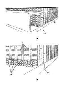
With reference to Figure 17 in an alternative arrangement, tubes 40 are
provided
in the walls 8 of the grid to further aid the circulation of temperature
controlled gas
from reservoir 6 or temperature controlled fluids from elsewhere to reduce the
temperature variation throughout the storage stacks. The tubes 40 can be used
to
either draw or force fluids through the storage system.
Moreover, the temperature controlled air may be further directed and
circulated
through ducting or holes and cavities within the uprights and framework 14
structure of the storage system.
It will be appreciated that the foregoing embodiments are described in terms
of a
temperature control system for a storage system such as that used as part of
an
online retail operation. However, it will be appreciated that a similar form
of
temperature control system may be used in a similar structure of storage
system
used for other applications. For example, use of such storage systems has been
envisaged for a mechanized greenhouse wherein the containers 10 contain
plants or other living organisms growing under controlled conditioned. In such
systems, control of temperature may be critical but additionally humidity, air
flow
and other environmental variables may require control. It will be appreciated
that
use of the temperature controlling system hereinbefore describe may
advantageously assist in the control of humidity, air flow and the like.
It has been shown that the growth of plants and other living organisms has
been
greatly affected by air flow across said plants or organisms. Accordingly, the
use
of a temperature control system based on air flow may be advantageous in such
applications.
Many variations and modifications not explicitly described above are also
possible without departing from the scope of the invention as defined in the
appended claims.
11