Note: Descriptions are shown in the official language in which they were submitted.
CA 02988042 2017-12-01
SPECIFICATION
Title of Invention: MODE TRANSITION CONTROL DEVICE FOR HYBRID
VEHICLE
Technical Field
[0001] The present invention relates to a mode transition control device
for a hybrid
vehicle that carries out a mode transition from a series traveling mode to a
parallel traveling
mode by a shift of a transmission.
Background Art
[0002] Conventionally, a control device that has a series traveling mode in
which the
drive wheels are driven using only motor power and a parallel traveling mode
in which the
drive wheels are driven using motor power and engine power, and that selects
between these
traveling modes based on the traveling state of the vehicle, is known (for
example, refer to
Patent Document 1).
Prior Art Documents
Patent Documents
[0003] Patent Document 1: Japanese Laid-Open Patent Application No. 2005-
226810
Summary of the Invention
The Problem to be Solved by the Invention
[0004] In the conventional device, for example, the series traveling mode
is set at the
time of a start when drive torque is required, and the parallel traveling mode
is set if a high
output is required as the vehicle speed is increased. However, if there is a
great change in the
rotational speed of the engine when switching from the series traveling mode
to the parallel
traveling mode, there is the risk of imparting discomfort to the driver.
[0005] In view of the problem described above, an object of the present
invention is to
provide a mode transition control device for a hybrid vehicle that reduces
discomfort that
may be imparted to the driver at the time of a mode transition from a series
traveling mode to
a parallel traveling mode during travel.
Means of Achieving the Object
[0006] In order to achieve the object above, the mode transition control
device for a
hybrid vehicle of the present invention comprises a first electric motor, a
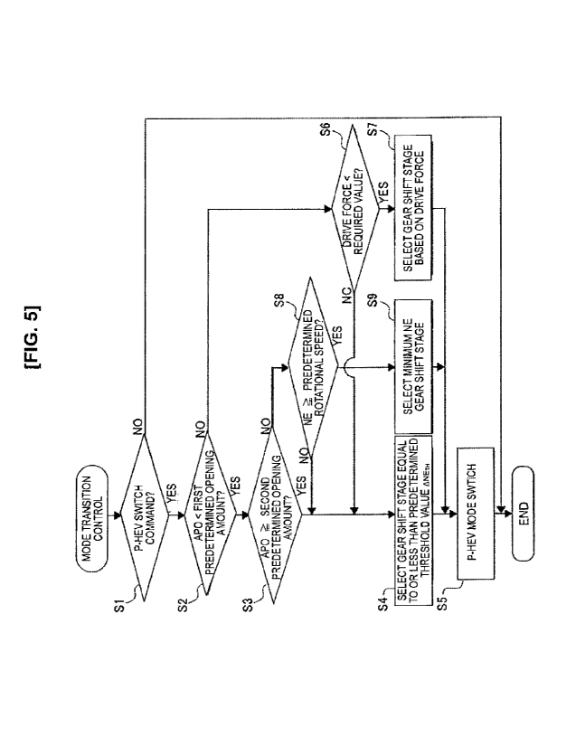
second electric
motor, and an internal combustion engine as power sources, and a transmission
that is able to
shift and transmit the output from the power sources to the drive wheel.
In the transmission, a mode transition is possible between a series traveling
mode, in which the drive wheel is driven by the first electric motor while
generating power
CA 02988042 2017-12-01
2
with the second electric motor by being driven by the internal combustion
engine, and a
parallel traveling mode, in which the drive wheel is driven by both the first
electric motor and
the internal combustion engine.
The hybrid vehicle is provided with a mode transition controller for switching
the
ICE gear shift stage that shifts the output of the internal combustion engine
if there is a mode
transition request.
The mode transition controller selects, as the ICE gear shift stage, a gear
shift
stage in which the rotational speed change amount of the internal combustion
engine
accompanying a mode transition is less than or equal to a predetermined
threshold value, at
the time of a mode transition from the series traveling mode to the parallel
traveling mode.
More specifically, in one embodiment the present invention provides a mode
transition control device for a hybrid vehicle having:
a first electric motor, a second electric motor and an internal combustion
engine as
drive sources, and having a transmission that is configured to shift and
transmit an output
from the power sources to a drive wheel, wherein the transmission is
configured to make a
mode transition possible between a series traveling mode, in which the drive
wheel is driven
by the first electric motor while generating power with the second electric
motor by a drive of
the internal combustion engine, and a parallel traveling mode, in which the
drive wheel is
driven by both the first electric motor and the internal combustion engine;
the mode transition control device comprising:
a mode transition controller that switches an ICE gear shift stage that shifts
the
output of the internal combustion engine upon existence of a mode transition
request;
wherein the mode transition controller selects the ICE gear shift stage that
is
selected based on the rotational speed change amount of the internal
combustion
engine accompanying a mode transition, and a gear shift stage in which a
rotational
speed change amount of the internal combustion engine accompanying a mode
transition is less than or equal to a predetermined threshold value, at the
time of a
mode transition from the series traveling mode to the parallel traveling mode.
Effects of the Invention
[0007] That is, when a mode transition is executed, the rotational speed of
the internal
combustion engine is switched from a power generation rotational speed for
ensuring power
CA 02988042 2017-12-01
=
2a
generation by the second electric motor (engine rotation speed in the series
traveling mode) to
a rotational speed that is determined from the transmission ratio of the
traveling vehicle speed
and the ICE gear shift stage (engine rotation speed in the parallel traveling
mode).
In the present invention, at this time, a gear shift stage in which the
rotational
speed change amount of the internal combustion engine accompanying the mode
transition is
less than or equal to a predetermined threshold value is selected as the ICE
gear shift stage.
As a result, it is possible to reduce the discomfort that may be imparted to
the
driver at the time of a mode transition from the series traveling mode to the
parallel traveling
mode.
Brief Description of the Drawings
[0008] [Figure I] is an overall system diagram illustrating a drive
system and a control
system of a hybrid vehicle to which is applied the mode transition control
device of the first
embodiment.
[Figure 2] is a control system block diagram illustrating the configuration of
a
shift control system of a multistage gear transmission mounted in a hybrid
vehicle to which is
applied the mode transition control device of the first embodiment.
[Figure 3] is a schematic overview of a shift map illustrating a concept of
switching the gear shift pattern in a multistage gear transmission mounted on
a hybrid vehicle
to which is applied the mode transition control device of the first
embodiment.
[Figure 4] is a gear shift pattern table illustrating the gear shift patterns
recited in
the switching positions of three engagement clutches in a multistage gear
transmission
CA 02988042 2017-12-01
3
mounted in a hybrid vehicle to which is applied the transmission control
device of the first
embodiment.
[Figure 5] is a flowchart illustrating the sequence of mode transition control
steps
carried out in a transmission control unit of the first embodiment.
[Figure 6] is a schematic overview of a mode switch map illustrating a concept
of
the mode transition control process carried out in a transmission control unit
of the first
embodiment.
[Figure 7] is a schematic overview of a shift map illustrating how to select
an
ICE gear shift stage when executing the mode transition control process of the
first
embodiment.
[Figure 8] is an explanatory view illustrating the engine rotation speed
during
series traveling of a hybrid vehicle to which is applied the mode transition
control device of
the first embodiment.
[Figure 9A] is a torque flow diagram illustrating the flow of the ICE torque
and
the MG1 torque in a multistage gear transmission when a gear shift pattern of
the series HEV
mode is selected.
[Figure 9B] is a torque flow diagram illustrating the flow of the MG1 torque
in a
multistage gear transmission when "EVlst ICE3rd" is selected, as one example
of a gear shift
pattern in the parallel HEV mode.
[Figure 10] is a time chart illustrating each characteristic at the time of
execution
of the flowchart of Figure 5.
[Figure 11] is a schematic overview of a shift map illustrating how to select
an
ICE gear shift stage when executing the mode transition control process of the
second
embodiment.
Embodiments to Carry Out the Invention
[0009] A preferred embodiment for realizing the mode transition control
device for an
electrically driven vehicle of the present invention is explained below based
on the first
embodiment illustrated in the drawings.
First Embodiment
[0010] The configuration is described first.
The mode transition control device of the first embodiment is applied to a
hybrid
vehicle (one example of an electrically driven vehicle), comprising, as drive
system
components, one engine (internal combustion engine), two motor/generators, and
a
multistage gear transmission having three engagement clutches. The "overall
system
CA 02988042 2017-12-01
4
configuration," the "configuration of the shift control system," the
"configuration of the gear
shift patterns," and the "configuration of the mode transition control
process" will be
described separately below with regard to the configuration of the mode
transition control
device for a hybrid vehicle in the first embodiment.
[0011] [Overall system configuration]
Figure 1 illustrates a drive system and a control system of a hybrid vehicle
to
which is applied the mode transition control device of the first embodiment.
The overall
system configuration will be described below based on Figure 1.
[0012] The drive system of the hybrid vehicle comprises an internal
combustion engine
ICE, a first motor/generator MG1 (electric motor), a second motor/generator
MG2, and a
multistage gear transmission 1 having three engagement clutches Cl, C2, C3, as
illustrated in
Figure 1. Here, "ICE" is an acronym for "Internal Combustion Engine."
[0013] The internal combustion engine ICE is, for example, a gasoline
engine or a diesel
engine that is disposed in a front area of a vehicle such that the crankshaft
direction is aligned
with the vehicle width direction. The internal combustion engine ICE is
connected to a
transmission case 10 of the multistage gear transmission 1, and the output
shaft of the internal
combustion engine is connected to a first shaft 11 of the multistage gear
transmission I. The
internal combustion engine ICE basically carries out an MG2 start, where the
second
motor/generator MG2 is used as a starter motor. However, a starter motor 2
remains
available for when an MG2 start using a high-power battery 3 cannot be
ensured, such as
during extreme cold.
[0014] Both the first motor/generator MG1 and the second motor/generator
MG2 are
permanent-magnet type synchronous motors utilizing three-phase alternating
current, having
the high-power battery 3 as a common power source. The stator of the first
motor/generator
MG I is fixed to a case of the first motor/generator MG1, and the case is
fixed to the
transmission case 10 of the multistage gear transmission 1. Then, a first
motor shaft
integrated with a rotor of the first motor/generator MG1 is connected to a
second shaft 12 of
the multistage gear transmission 1. The stator of the second motor/generator
MG2 is fixed to
a case of the second motor/generator MG2, and the case is fixed to the
transmission case 10
of the multistage gear transmission 1. Then, a second motor shaft integrated
with a rotor of
the second motor/generator MG2 is connected to a sixth shaft 16 of the
multistage gear
transmission 1. A first inverter 4, which converts direct current into three-
phase alternating
current during powering and converts three-phase alternating current into
direct current
during regeneration, is connected to a stator coil of the first
motor/generator MG1, via a first
CA 02988042 2017-12-01
AC harness 5. A second inverter 6, which converts direct current into three-
phase alternating
current during powering and converts three-phase alternating current into
direct current
during regeneration, is connected to a stator coil of the second
motor/generator MG2, via a
second AC harness 7. The high-power battery 3, the first inverter 4, and the
second inverter 6
are connected by a DC harness 8, via a junction box 9.
[0015] The multistage gear transmission 1 is a normally meshing
transmission
comprising a plurality of gear pairs having different transmission ratios, and
comprises six
gear shafts 11-16 provided with gears and disposed parallel to each other
inside the
transmission case 10, and three engagement clutches Cl, C2, C3 for selecting a
gear pair. A
first shaft 11, a second shaft 12, a third shaft 13, a fourth shaft 14, a
fifth shaft 15, and a sixth
shaft 16 are provided as gear shafts. A first engagement clutch Cl, a second
engagement
clutch C2, and a third engagement clutch C3 are provided as engagement
clutches. The
transmission case 10 is provided with an electric oil pump 20 that supplies
lubrication oil to
the meshing portions of the gears and the axle bearing portions inside the
case.
[0016] The first shaft 11 is a shaft to which the internal combustion
engine ICE is
connected, and a first gear 101, a second gear 102, and a third gear 103 are
disposed relative
to the first shaft 11, in that order from the right in Figure 1. The first
gear 101 is integrally
provided (including integral attachment) to the first shaft 11. The second
gear 102 and the
third gear 103 are idling gears, in which a boss portion that protrudes in the
axial direction is
inserted into the outer perimeter of the first shaft 11, and are provided so
as to be drivably
connectable to the first shaft 11 via the second engagement clutch C2.
[0017] The second shaft 12 is a shaft to which the first motor/generator
MG1 is
connected, and is a cylindrical shaft that is coaxially disposed with the axis
aligned with the
outer side position of the first shaft 11, and a fourth gear 104 and a fifth
gear 105 are disposed
relative to the second shaft 12, in that order from the right in Figure 1. The
fourth gear 104
and the fifth gear 105 are integrally provided (including integral attachment)
to the second
shaft 12.
[0018] The third shaft 13 is a shaft disposed on the output side of the
multistage gear
transmission 1, and a sixth gear 106, a seventh gear 107, an eighth gear 108,
a ninth gear 109,
and a tenth gear 110 are disposed relative to the third shaft 13, in that
order from the right in
Figure 1. The sixth gear 106, the seventh gear 107, and the eighth gear 108
are integrally
provided (including integral attachment) to the third shaft 13. The ninth gear
109 and the
tenth gear 110 are idling gears, in which a boss portion that protrudes in the
axial direction is
inserted into the outer perimeter of the third shaft 13, and are provided so
as to be drivably
CA 02988042 2017-12-01
6
connectable to the third shaft 13 via the third engagement clutch C3. Then,
the sixth gear 106
meshes with the second gear 102 of the first shaft 11, the seventh gear 107
meshes with a
sixteenth gear 116 of a differential gear 17, and the eighth gear 108 meshes
with the third
gear 103 of the first shaft 11. The ninth gear 109 meshes with the fourth gear
104 of the
second shaft 12, and the tenth gear 110 meshes with the fifth gear 105 of the
second shaft 12.
[0019] The fourth shaft 14 is a shaft in which both ends are supported in
the
transmission case 10, and an eleventh gear 111, a twelfth gear 112, and a
thirteenth gear 113
are disposed relative to the fourth shaft 14, in that order from the right in
Figure 1. The
eleventh gear 111 is integrally provided (including integral attachment) to
the fourth shaft 14.
The twelfth gear 112 and the thirteenth gear 113 are idling gears, in which a
boss portion that
protrudes in the axial direction is inserted into the outer perimeter of the
fourth shaft 14, and
are provided so as to be drivably connectable to the fourth shaft 14 via the
first engagement
clutch Cl. Then, the eleventh gear 111 meshes with the first gear 101 of the
first shaft 11, the
twelfth gear 112 meshes with a second gear 102 of the first shaft 11, and the
thirteenth gear
113 meshes with the fourth gear 104 of the second shaft 12.
[0020] The fifth shaft 15 is a shaft in which both ends are supported in
the transmission
case 10, and a fourteenth gear 114 that meshes with the eleventh gear 111 of
the fourth shaft
14 is integrally provided thereto (including integral attachment).
[0021] The sixth shaft 16 is a shaft to which the second motor/generator
MG2 is
connected, and a fifteenth gear 115 that meshes with the fourteenth gear 114
of the fifth shaft
15 is integrally provided thereto (including integral attachment).
[0022] The second motor/generator MG2 and the internal combustion engine
ICE are
mechanically connected to each other by a gear train configured from the
fifteenth gear 115,
the fourteenth gear 114, the eleventh gear 111, and the first gear 101, which
mesh with each
other. The gear train serves as a reduction gear train that decelerates the
MG2 rotation speed
at the time of an MG2 start of the internal combustion engine ICE by the
second
motor/generator MG2, and serves as a speed increasing gear train that
accelerates the engine
rotation speed at the time of MG2 power generation for generating the second
motor/generator MG2, by the driving of the internal combustion engine ICE.
[0023] The first engagement clutch Cl is a dog clutch that is interposed
between the
twelfth gear 112 and the thirteenth gear 113 of the fourth shaft 14, and that
is engaged by an
engagement stroke in a rotationally synchronized state without possessing a
synchronization
mechanism. When the first engagement clutch Cl is in a left engagement
position (Left), the
fourth shaft 14 and the thirteenth gear 113 are drivingly connected. When the
first
CA 02988042 2017-12-01
7
engagement clutch Cl is in a neutral position (N), the fourth shaft 14 and the
twelfth gear 112
are released, and the fourth shaft 14 and the thirteenth gear 113 are
released. When the first
engagement clutch Cl is in a right engagement position (Right), the fourth
shaft 14 and the
twelfth gear 112 are drivingly connected.
[0024] The second engagement clutch C2 is a dog clutch that is interposed
between the
second gear 102 and the third gear 103 of the first shaft 11, and that is
engaged by an
engagement stroke in a rotationally synchronized state without possessing a
synchronization
mechanism. When the second engagement clutch C2 is in a left engagement
position (Left),
the first shaft 11 and the third gear 103 are drivingly connected. When the
second
engagement clutch C2 is in a neutral position (N), the first shaft 11 and the
second gear 102
are released, and the first shaft 11 and the third gear 103 are released. When
the second
engagement clutch C2 is in a right engagement position (Right), the first
shaft 11 and the
second gear 102 are drivingly connected.
[0025] The third engagement clutch C3 is a dog clutch that is interposed
between the
ninth gear 109 and the tenth gear 110 of the third shaft 13, and that is
engaged by an
engagement stroke in a rotationally synchronized state without possessing a
synchronization
mechanism. When the third engagement clutch C3 is in a left engagement
position (Left), the
third shaft 13 and the tenth gear 110 are drivingly connected. When the third
engagement
clutch C3 is in a neutral position (N), the third shaft 13 and the ninth gear
109 are released,
and the third shaft 13 and the tenth gear 110 are released. When the third
engagement clutch
C3 is in a right engagement position (Right), the third shaft 13 and the ninth
gear 109 are
drivingly connected. Then, a sixteenth gear 116 that meshes with the seventh
gear 107
integrally provided (including integral attachment) to the third shaft 13 of
the multistage gear
transmission 1 is connected to left and right drive wheels 19 via the
differential gear 17 and
left and right drive shafts 18.
[0026] The control system of the hybrid vehicle comprises a hybrid control
module 21, a
motor control unit 22, a transmission control unit 23, and an engine control
unit 24, as
illustrated in Figure 1.
[0027] The hybrid control module 21 (acronym: "HCM") is an integrated
control means
having a function to appropriately manage the energy consumption of the entire
vehicle. This
hybrid control module 21 is connected to the other control units (motor
control unit 22,
transmission control unit 23, engine control unit 24, etc.) so as to be
capable of bidirectional
information exchange via a CAN communication line 25. The "CAN" in CAN
communication line 25 is an acronym for "Controller Area Network."
CA 02988042 2017-12-01
8
[0028] The motor control unit 22 (acronym: "MCU") carries out powering
control,
regeneration control, and the like, of the first motor/generator MG1 and the
second
motor/generator MG2 via control commands to the first inverter 4 and the
second inverter 6.
The control modes for the first motor/generator MG1 and the second
motor/generator MG2
are "torque control" and "rotational speed FB control." In the "torque
control," a control is
carried out in which the actual motor torque is caused to follow a target
motor torque, when a
target motor torque to be shared with respect to a target drive force is
determined. In the
"rotational speed FB control," a control is carried out in which a target
motor rotation speed,
with which the input-output rotational speeds of the clutch are synchronized,
is determined,
and an FB torque is output so as to converge the actual motor rotation speed
with the target
motor rotation speed, when there is a gear shift request to meshing engage any
one of the
engagement clutches Cl, C2, C3 during travel.
[0029] The transmission control unit 23 (acronym: "TMCU") carries out a
shift control
for switching the gear shift pattern of the multistage gear transmission 1, by
outputting a
current command to electric actuators 31, 32, 33 (refer to Figure 2), based on
predetermined
input information. In this shift control, the engagement clutches Cl, C2, C3
are selectively
meshing-engaged/meshing-disengaged, and a gear pair involved in power
transmission is
selected from the plurality of pairs of gear pairs. Here, at the time of a
gear shift request to
engage any one of the released engagement clutches Cl, C2, C3, in order to
suppress
differential rotation speed between the input-output of the clutch to ensure
meshing
engagement, a rotational speed FB control (rotation synchronization control)
of the first
motor/generator MG1 or the second motor/generator MG2 is used in combination.
[0030] The engine control unit 24 (acronym: "ECU") carries out start
control of the
internal combustion engine ICE, stop control of the internal combustion engine
ICE, fuel cut
control, and the like by outputting a control command to the motor control
unit 22, spark
plugs, fuel injection actuator, or the like, based on predetermined input
information.
[0031] [Configuration of the Shift Control System]
The multistage gear transmission I according to the first embodiment is
characterized in that efficiency is achieved by reducing drag by employing, as
shifting
elements, engagement clutches Cl, C2, C3 (dog clutch) that are meshing
engaged. Then,
when there is a gear shift request to mesh and engage any one of the
engagement clutches Cl,
C2, C3, the differential rotation speeds of the input-output of the clutch are
synchronized with
the first motor/generator MG1 (when the engagement clutch C3 is engaged) or
the second
motor/generator MG2 (when the engagement clutches Cl, C2 are engaged), and an
CA 02988042 2017-12-01
9
engagement stroke is started once the rotational speed falls within a
synchronization
determination rotational speed range, to realize the gear shift. In addition,
when there is a
gear shift request to release any one of the engaged engagement clutches Cl,
C2, C3, the
clutch transmission torque of the release clutch is reduced, and a
disengagement stroke is
started once the torque becomes less than or equal to a release torque
determination value, to
realize the gear shift. The configuration of the shift control system of the
multistage gear
transmission 1 is described below based on Figure 2.
[0032] The shift control system comprises, as engagement clutches, a first
engagement
clutch Cl, a second engagement clutch C2, and a third engagement clutch C3, as
illustrated in
Figure 2. A first electric actuator 31, a second electric actuator 32, and a
third electric
actuator 33 are provided as actuators. A first engagement clutch operating
mechanism 41, a
second engagement clutch operating mechanism 42, and a third engagement clutch
operating
mechanism 43 are provided as mechanisms that convert actuator operations into
clutch
engagement/disengagement operations. Furthermore, a transmission control unit
23 is
provided as a control means of the first electric actuator 31, the second
electric actuator 32,
and the third electric actuator 33.
[0033] The first engagement clutch Cl, the second engagement clutch C2, and
the third
engagement clutch C3 are dog clutches that switch between a neutral position
(N: disengaged
position), a left engagement position (Left: left side clutch meshing-
engagement position),
and a right engagement position (Right: right side clutch meshing-engagement
position). The
engagement clutches CI, C2, C3 all have the same configuration, comprising
coupling
sleeves 51, 52, 53, left dog clutch rings 54, 55, 56, and right dog clutch
rings 57, 58, 59. The
coupling sleeves 51, 52, 53 are provided so as to be strokable in the axial
direction by a spline
connection via a hub, which is not shown, fixed to the fourth shaft 14, the
first shaft 11, and
the third shaft 13, and have dog teeth 51a, 51b, 52a, 52b, 53a, 53b on both
sides having flat
top surfaces. Furthermore, fork grooves 51c, 52c, 53c are provided relative to
the
circumferential center portions of the coupling sleeves 51, 52, 53. The left
dog clutch rings
54, 55, 56 are fixed to the boss portions of the gears 113, 103, 110, which
are left idling gears
of the engagement clutches Cl, C2, C3, and have dog teeth 54a, 55a, 56a with
flat top
surfaces that oppose the dog teeth 51a, 52a, 53a. The right dog clutch rings
57, 58, 59 are
fixed to the boss portions of the gears 112, 102, 109, which are right idling
gears of the
engagement clutches Cl, C2, C3, and have dog teeth 57b, 58b, 59b with flat top
faces that
oppose the dog teeth 51b, 52b, 53b.
CA 02988042 2017-12-01
[0034] The first engagement clutch operating mechanism 41, the second
engagement
clutch operating mechanism 42, and the third engagement clutch operating
mechanism 43 are
mechanisms for converting the turning motions of the electric actuators 31,
32, 33 into axial
stroke motions of the coupling sleeves 51, 52, 53. The engagement clutch
operating
mechanisms 41, 42, 43 all have the same configuration, comprising turning
links 61, 62, 63,
shift rods 64, 65, 66, and shift forks 67, 68, 69. One end of each of the
turning links 61, 62,
63 is provided relative to the actuator shaft of the electric actuators 31,
32, 33, respectively,
and each of the other ends is connected to the shift rods 64, 65, 66,
respectively, so as to be
relatively displaceable. The shift rods 64, 65, 66 are configured to be
capable of expanding
and contracting as a function of the magnitude and direction of the rod
transmitting force by
means of springs 64a, 65a, 66a interposed in the rod dividing positions. One
end of each of
the shift forks 67, 68, 69 is fixed to the shift rods 64, 65, 66,
respectively, and each of the
other ends are respectively disposed in the fork grooves 51c, 52c, 53c of the
coupling sleeves
51, 52, 53.
[0035] The transmission control unit 23 inputs sensor signals and switch
signals from a
vehicle speed sensor 71, an accelerator position opening amount sensor 72, a
transmission
output shaft rotation speed sensor 73, an engine rotation speed sensor 74, an
MG1 rotation
speed sensor 75, an MG2 rotation speed sensor 76, an inhibitor switch 77, and
the like. The
transmission output shaft rotation speed sensor 73 is provided relative to the
shaft end portion
of the third shaft 13 and detects the shaft rotation speed of the third shaft
13. Then, a position
servo control unit (for example, a position servo system by PID control) is
provided, which
controls meshing-engagement and disengagement of the engagement clutches Cl,
C2, C3,
determined by the positions of the coupling sleeves 51, 52, 53. The position
servo control
unit inputs sensor signals from a first sleeve position sensor 81, a second
sleeve position
sensor 82, and a third sleeve position sensor 83. Then, the sensor values of
the sleeve
position sensors 81, 82, 83 are read, and current is imparted to the electric
actuators 31, 32,
33 such that the positions of the coupling sleeves 51, 52, 53 will be in the
disengaged position
or the engagement position according to an engagement stroke. That is, by
setting an
engaged state in which the dog teeth welded to the coupling sleeves 51, 52, 53
and the dog
teeth welded to the idling gears are both in engagement positions meshed with
each other, the
idling gears are drivingly connected to the fourth shaft 14, the first shaft
11, and the third
shaft 13. On the other hand, by setting a disengaged state in which the dog
teeth welded to
the coupling sleeves 51, 52, 53 and the dog teeth welded to the idling gears
are in non-
engagement positions by displacement of the coupling sleeves 51, 52, 53 in the
axial
CA 02988042 2017-12-01
11
direction, the idling gears are disconnected from the fourth shaft 14, the
first shaft 11, and the
third shaft 13.
[0036] [Configuration of the Gear Shift Pattern]
The multistage gear transmission 1 of the first embodiment features size
reduction achieved by reducing the power transmission loss without a
differential rotation
absorbing element, such as a fluid coupling, and by reducing ICE gear shift
stages (gear shift
stages of the internal combustion engine ICE) by providing motor assistance to
the internal
combustion engine ICE (EV gear shift stages: 1-2 speed, ICE gear shift stages:
1-4 speed).
The configuration of the gear shift pattern of the multistage gear
transmission 1 is described
below based on Figure 3 and Figure 4.
[0037] A concept of a gear shift pattern is employed in which, when the
vehicle speed
VSP is in a starting region that is less than or equal to a predetermined
vehicle speed VSPO,
since the multistage gear transmission 1 does not have a differential rotation
absorbing
element, a motor start by only the motor driving force is carried out in the
"EV mode," as
illustrated in Figure 3. Then, when in the traveling region and the demand for
driving force is
great, a "parallel HEV mode (parallel traveling mode)" is employed in which
the engine
driving force is assisted by the motor driving force, as illustrated in Figure
3. That is, as the
vehicle speed VSP increases, the ICE gear shift stages shift from (ICE 1st) ->
ICE2nd ->
ICE3rd -> ICE4th, and the EV gear shift stages (gear shift stages of the first
motor/generator
MG1) shift from EVIst -> EV2nd. Therefore, based on the concept of the above-
described
gear shift pattern, a shift map for issuing gear shift requests for switching
the gear shift
pattern is created.
The shift map illustrated in Figure 3 is created based on fuel efficiency and
electrical efficiency and is used in a state in which there is no excess or
deficiency in the
remaining battery SOC (State of Charge) of the high-power battery 3. In
addition, while not
shown, the transmission control unit 23 comprises a plurality of shift maps
according to the
remaining battery SOC (State of Charge) of the high-power battery 3.
[0038] The gear shift patterns obtainable by the multistage gear
transmission 1 having
engagement clutches Cl, C2, C3 are as shown in Figure 4. In Figure 4, "Lock"
represents an
interlock pattern that is not applicable as a gear shift pattern, "EV-"
represents a state in
which the first motor/generator MG1 is not drivingly connected to the driving
wheels 19, and
"ICE-" represents a state in which the internal combustion engine ICE is not
drivingly
connected to the driving wheels 19. During the shift control, it is not
necessary to use all the
CA 02988042 2017-12-01
12
gear shift patterns shown in Figure 4, and it is of course possible to select
from these gear
shift patterns according to need. Each of the gear shift patterns is described
below.
[0039] When the second engagement clutch C2 is in "N" and the third
engagement
clutch C3 is in "N," the following gear shift patterns are obtained according
to the position of
the first engagement clutch Cl. "EV- ICEgen" is obtained if the first
engagement clutch Cl
is in "Left," "Neutral" is obtained if the first engagement clutch Cl is in
"N," and "EV-
ICE3rd" is obtained if the first engagement clutch Cl is in "Right."
Here, the gear shift pattern "EV- ICEgen" is a pattern selected at the time of
MG1
idle power generation, in which power is generated in the first
motor/generator MG1 by the
internal combustion engine ICE when the vehicle is stopped, or, at the time of
double idle
power generation, in which MG2 power generation is carried out in addition to
MG1 power
generation. The gear shift pattern "Neutral" is a pattern selected at the time
of MG2 idle
power generation, in which power is generated in the second motor/generator
MG2 by the
internal combustion engine ICE when the vehicle is stopped.
[0040] When the second engagement clutch C2 is in "N" and the third
engagement
clutch C3 is in "Left," the following gear shift patterns are obtained
according to the position
of the first engagement clutch Cl. "EVlst ICElst" is obtained if the first
engagement clutch
Cl is in "Left," "EVlst ICE-" is obtained if the first engagement clutch Cl is
in "N," and
"EVlst ICE3rd" is obtained if the first engagement clutch Cl is in "Right."
Here, the gear shift pattern "EV I st ICE-" is an "EV mode" pattern in which
the
internal combustion engine ICE is stopped and travel is carried out by the
first
motor/generator MG!, or a "series HEV mode (series traveling mode. Shown as
'Se-HEV' in
Figure 4, etc.)" pattern in which a first-speed EV travel is carried out by
the first
motor/generator MG1 while power is generated in the second motor/generator MG2
by the
internal combustion engine ICE.
For example, when traveling while selecting the "series HEV mode" by "EVI st
ICE-," the first engagement clutch Cl is switched from "N" to "Left," based on
a deceleration
due to insufficient driving force. In this case, the vehicle transitions to
traveling by the
"parallel HEV mode (first speed)" according to the "EVlst ICElst" gear shift
pattern, in
which the driving force is secured.
[0041] When the second engagement clutch C2 is in "Left" and the third
engagement
clutch C3 is in "Left," "EVlst ICE2nd" is obtained if the position of the
first engagement
clutch Cl is in "N."
CA 02988042 2017-12-01
13
For example, if the driving force requirement is increased during first-speed
EV
traveling while selecting the "series HEV mode" by "EV I st ICE-," the second
engagement
clutch C2 is switched from "N" to "Left." In this case, the vehicle
transitions to traveling by a
"parallel HEV mode" according to the "EV 1St ICE2nd" gear shift pattern, in
which the
driving force is secured.
[0042] When the second engagement clutch C2 is in "Left" and the third
engagement
clutch C3 is in "N," the following gear shift patterns are obtained according
to the position of
the first engagement clutch Cl. "EV1.5 ICE2nd" is obtained if the first
engagement clutch
CI is in "Left," and "EV- ICE2nd" is obtained if the first engagement clutch
Cl is in "N."
[0043] When the second engagement clutch C2 is in "Left" and the third
engagement
clutch C3 is in "Right," "EV2nd ICE2nd" is obtained if the position of the
first engagement
clutch Cl is in "N."
For example, when traveling in the "parallel HEV mode" while selecting the
"EVlst ICE2nd" gear shift pattern, the third engagement clutch C3 is switched
from "Left" to
"Right" via "N," according to an up-shift request. In this case, the vehicle
transitions to
traveling by the "parallel HEV mode" according to the "EV2nd ICE2nd" gear
shift pattern, in
which the EV gear shift stage is set to second speed.
For example, when traveling in the "parallel HEV mode" while selecting the
"EV2nd ICE4th" gear shift pattern, the second engagement clutch C2 is switched
from
"Right" to "Left" via "N," according to a downshift request. In this case, the
vehicle
transitions to traveling by the "parallel HEV mode" according to the "EV2nd
ICE2nd" gear
shift pattern, in which the ICE gear shift stage is set to second speed.
[0044] When the second engagement clutch C2 is in "N" and the third
engagement
clutch C3 is in "Right," the following gear shift patterns are obtained
according to the
position of the first engagement clutch Cl. "EV2nd ICE3rd" is obtained if the
first
engagement clutch Cl is in "Left," "EV2nd ICE-" is obtained if the first
engagement clutch
Cl is in "N," and "EV2nd ICE3rd" is obtained if the first engagement clutch Cl
is in "Right."
Here, the gear shift pattern "EV2nd ICE-" is an "EV mode" pattern, in which
the
internal combustion engine ICE is stopped and travel is carried out by the
first
motor/generator MG1, or a "series HEV mode" pattern, in which a second-speed
EV travel is
carried out by the first motor/generator MG1 while power is generated in the
second
motor/generator MG2 by the internal combustion engine ICE.
Therefore, for example, when traveling in the "parallel HEV mode" while
selecting the "EV2nd ICE2nd" gear shift pattern, the second engagement clutch
C2 is
CA 02988042 2017-12-01
14
switched from "Left" to "N" and the first engagement clutch Cl is switched
from "N" to
"Right," according to an up-shift request. In this case, the vehicle
transitions to traveling by
the "parallel HEV mode" according to the "EV2nd ICE3rd" gear shift pattern, in
which the
ICE gear shift stage is set to third speed.
[0045] When the second engagement clutch C2 is in "Right" and the third
engagement
clutch C3 is in "Right," "EV2nd ICE4th" is obtained if the position of the
first engagement
clutch Cl is in "N."
When the second engagement clutch C2 is in "Right" and the third engagement
clutch C3 is in "N," the following gear shift patterns are obtained according
to the position of
the first engagement clutch Cl. "EV2.5 ICE4th" is obtained if the first
engagement clutch Cl
is in "Left," and "EV- ICE4th" is obtained if the first engagement clutch Cl
is in "N."
[0046] When the second engagement clutch C2 is in "Right" and the third
engagement
clutch C3 is in "Left," "EVlst ICE4th" is obtained if the position of the
first engagement
clutch Cl is in "N."
[0047] [Configuration of the Mode Transition Control Process]
Figure 5 illustrates the sequence of the mode transition control steps carried
out
in the transmission control unit 23 (mode transition controller) of the first
embodiment. More
specifically, Figure 5 illustrates the sequence of steps when switching the
mode from the
series HEV mode (series traveling mode) to the parallel HEV mode (parallel
traveling mode.
Represented as "P-HEV" in Figure 5, etc.).
Each of the steps in Figure 5, which shows one example of the configuration of
the mode transition control process, will be described below. The steps of
Figure 5 are
repeatedly executed while the vehicle is traveling in the series HEV mode.
[0048] In Step S I , it is determined whether or not a mode switching
command to the
parallel HEV mode has been output. A switching command to the parallel HEV
mode is
output based on the mode switch map illustrated in Figure 6, using vehicle
speed and drive
force as parameters.
[0049] That is, if the operating point is on the mode switching boundary
line shown in
Figure 6 as the vehicle speed and the drive force change, the mode switching
command in
Step S I is output.
Here, the mode switching boundary line shown in Figure 6 is appropriately
changed according to the SOC of the high-power battery 3. That is, since it is
desirable to
use the internal combustion engine ICE as a drive source earlier as the SOC of
the high-
CA 02988042 2017-12-01
power battery 3 is lower, the mode switching boundary line is shifted to the
lower speed side
(left side in the figure).
[0050] If the outcome of the determination of Step S1 is YES (switching
command to
parallel HEV mode present), the process proceeds to Step S2, and it is
determined whether or
not the accelerator position opening amount APO is less than a first
predetermined opening
amount. The first predetermined opening amount is set to a value with which it
can be
determined that the acceleration request for the vehicle by the driver is
large, and that the
required driving force is high. In other words, it is set to a value with
which it can be
determined that it is highly necessary to execute a shift control with
priority given to the
required driving force.
The accelerator position opening amount APO can be obtained from an output of
an accelerator position opening amount sensor 72. In addition, if the outcome
of the
determination of Step Si is NO (switching command to parallel HEV mode
absent), the
following process is skipped, and the program is ended.
[0051] If the outcome of the determination of Step S2 is YES (accelerator
position
opening amount APO < first predetermined opening amount), the process proceeds
to Step
S3, and it is determined whether or not the accelerator position opening
amount APO is
greater than or equal to a second predetermined opening amount, which is set
to a value that
is smaller than the first predetermined opening amount. The second
predetermined opening
amount is set to a value with which it can be determined that the vehicle is
traveling at a low
speed, and that the required driving force is low. In other words, the second
predetermined
opening amount is set to a value with which it can be determined whether the
vehicle is in a
traveling region that is likely to impart discomfort to the driver.
[0052] If the outcome of the determination of Step S3 is YES (accelerator
position
opening amount APO > second predetermined opening amount), then the process
proceed to
Step S4, and a gear shift stage in which the rotational speed change amount
ANE of an
internal combustion engine ICE accompanying a mode transition is less than or
equal to a
predetermined threshold value ANETH, or, more preferably, a gear shift stage
in which the
rotational speed change amount ANE of the internal combustion engine ICE
accompanying a
mode transition becomes the smallest, is selected as the ICE gear shift stage
after the
transition to the parallel HEV mode.
That is, the transmission control unit 23 according to the first embodiment
selects
an ICE gear shift stage using the shift map illustrated in Figure 3 in normal
shifting.
However, if transitioning from the series HEV mode to the parallel HEV mode,
the
CA 02988042 2017-12-01
16
transmission control unit 23 selects the ICE gear shift stage based on the
rotational speed
change amount ANE of the internal combustion engine ICE accompanying the mode
transition rather than the shift map illustrated in Figure 3, which is based
on fuel efficiency
and electric efficiency.
[0053] The selection of the ICE gear shift stage in Step S4 will be
described with
reference to Figure 6 and Figure 7. Figure 7 is a shift map of the internal
combustion engine
ICE. In Figure 6, the case is considered in which the operating point at the
time of a mode
transition from the series HEV mode to the parallel HEV mode is, for example,
operating
point A (vehicle speed V1).
[0054] The transmission control unit 23 can select ICE first speed, ICE
second speed,
ICE third speed, and ICE fourth speed as the ICE gear shift stage after
transition to the
parallel HEV mode, as illustrated in Figure 7. At the time of a mode
transition with the
operating point A (vehicle speed VI), if ICE first speed is selected as the
ICE gear shift stage
after a transition to the parallel HEV mode, the rotational speed change
amount of the internal
combustion engine ICE becomes ANEI. Similarly, if ICE second speed is
selected, the
rotational speed change amount is ANE2; if ICE third speed is selected, the
rotational speed
change amount is ANE3; and if ICE fourth speed is selected, the rotational
speed change
amount is ANE4.
Of the foregoing, the gear shift stages that become less than or equal to the
predetermined threshold value ANETH are ICE second speed and ICE third speed,
as
illustrated in Figure 7. Therefore, the transmission control unit 23 selects
one of ICE second
speed and ICE third speed (more preferably ICE third speed, with which the
rotational speed
change amount ANE of the internal combustion engine ICE becomes the smallest)
in Step S4.
The predetermined threshold value ANETH is appropriately set based on
discomfort that is imparted to the driver according to the vehicle speed at
the time of the
mode transition. Specifically, if the vehicle speed is low, since the driver
is likely to
experience discomfort with respect to a rotational speed change of the
internal combustion
engine ICE, the predetermined threshold value ANETH is set to a small value.
On the other
hand, if the vehicle speed is relatively high, the driver is less likely to
experience discomfort
with respect to a rotational speed change of the internal combustion engine
ICE; therefore,
the predetermined threshold value ANETH can be set to a relatively large
value.
That is, the predetermined threshold value ANETH is set according to the
vehicle
speed to a value that can ensure appropriate sound/vibration performance of
the vehicle
speed.
CA 02988042 2017-12-01
17
[0055] When the ICE gear shift stage after a transition to the parallel HEV
mode is
selected in Step S4, the steps then proceed to Step S5. In Step S5, shifting
to the ICE gear
shift stage selected in Step S4 is carried out, the traveling mode is switched
to the parallel
HEV mode, and the program is ended.
[0056] On the other hand, in the case of a NO outcome in Step S2
(accelerator position
opening amount APO > first predetermined opening amount), that is, if it is
determined that
the acceleration request from the driver is high, the process proceeds to Step
S6. In Step S6,
if the mode is caused to transition to the parallel HEV mode based on the
sound/vibration
performance, it is determined whether or not the drive force after the mode
transition is less
than the required driving force that is calculated according to the
accelerator position opening
amount APO, or the like. That is, upon switching to the parallel HEV mode, if
the vehicle is
shifted to an ICE gear shift stage with which the rotational speed change
amount ANE of the
internal combustion engine ICE becomes less than or equal to the predetermined
threshold
value ANErH, it is determined whether or not the drive force will be
insufficient.
In the example of Figure 7, as described above, the ICE gear shift stages at
which
the appropriate sound/vibration performance of the vehicle can be secured are
ICE second
speed and ICE third speed. Therefore, in Step S6, it is determined whether or
not the drive
forces that can be realized by ICE second speed or the ICE third speed will
both be less than
the driving force required for the driver.
[0057] If the outcome of the determination of Step S6 is YES (insufficient
driving
force), the process proceeds to Step S7, and an ICE gear shift stage is
selected based on the
required driving force. That is, even if the rotational speed change amount
ANE of the
internal combustion engine ICE is greater than or equal to the predetermined
threshold value
ANETH, an ICE gear shift stage that can satisfy the required driving force is
selected. Even if
the outcome of the determination of Step S6 is YES and an ICE gear shift stage
is selected
based on the required driving force, if there is a plurality of gear shift
stages from which the
selection can be made, the gear shift stage with which the rotational speed
change amount
ANE of the internal combustion engine ICE becomes smallest is selected.
[0058] Next, the process proceeds to Step S5, so that shifting to the ICE
gear shift stage
selected in Step S7 is carried out and the traveling mode is switched to the
parallel HEV
mode, after which the program is ended.
[0059] Additionally, in the case that the determination of Step S6 is NO
(the required
driving force is satisfied), the process proceeds to Step S4. When the process
proceeds from
S6 to S4, an ICE gear shift stage that satisfies the required driving force,
as well as an ICE
CA 02988042 2017-12-01
18
gear shift stage with which the rotational speed change amount ANE of the
internal
combustion engine ICE becomes less than or equal to the predetermined
threshold value
ANETE (more preferably the ICE gear shift stage with which the rotational
speed change
amount ANE of the internal combustion engine ICE becomes smallest), is
selected.
Therefore, in the example shown in Figure 7, if the drive force is
insufficient
with ICE third speed but the required driving force can be satisfied with ICE
second speed,
then the ICE second speed is selected.
[0060] In addition, in the case of a NO outcome in Step S3 (accelerator
position opening
amount APO < second predetermined opening amount), that is, if it is
determined that the
vehicle is traveling at a low speed and that the required driving force is
low, the process
proceeds to Step S8. In Step S8, it is determined whether or not the
rotational speed NE of
the internal combustion engine ICE is greater than or equal to a predetermined
rotational
speed. The predetermined rotational speed is set in consideration of the
sound/vibration
performance based on the current vehicle speed and the accelerator position
opening amount
APO. That is, the predetermined rotational speed is set to a rotational speed
that could impart
discomfort to the driver, compared with the current vehicle speed and
accelerator position
opening amount APO.
[0061] Figure 8 illustrates the engine rotational speed NE in the series
HEV mode. As
described above, in the series HEV mode, power is generated in the second
motor/generator
MG2 by the internal combustion engine ICE. Therefore, in the first embodiment,
a power
generation rotational speed for ensuring power generation by the second
motor/generator
MG2 is maintained during travel in the series HEV mode.
Thus, if low speed travel is carried out in the series HEV mode by the hybrid
vehicle according to the first embodiment, there are cases in which the
rotational speed NE
(power generation rotational speed) of the internal combustion engine ICE
becomes higher
compared with a target rotational speed that is calculated from the vehicle
speed and the
accelerator position opening amount APO in a normal vehicle, and discomfort
may be
imparted to the driver in terms of the sound/vibration performance.
Therefore, the predetermined rotational speed of Step S8 is set to a value
with
which it is possible to determine that the rotational speed NE (power
generation rotational
speed) of the internal combustion engine ICE in the series HEV mode is high
compared with
the current state of travel of the vehicle and that discomfort could be
imparted to the driver.
[0062] In the case of a YES outcome in Step S8 (rotational speed NE of
internal
combustion engine ICE > predetermined rotational speed), the process proceeds
to Step S9.
CA 02988042 2017-12-01
19
In Step 59, a gear shift stage with which the rotational speed NE of the
internal combustion
engine ICE after a transition to the parallel HEV mode becomes smallest (ICE
fourth speed in
the first embodiment) is selected.
[0063] Next, the process proceeds to Step S5, so that shifting to the ICE
gear shift stage
selected in Step S9 is carried out and the traveling mode is switched to the
parallel HEV
mode, after which the program is ended.
In the case of a NO outcome in Step S8 (rotational speed NE of internal
combustion engine ICE < predetermined rotational speed), the process proceeds
to Step S4
and the above-described process is carried out.
[0064] Next, the actions are described.
The "action of the mode transition control process," the "action of the mode
transition control," and the "characteristic action of the mode transition
control" will be
described separately, in terms of the actions of the mode transition control
device for a hybrid
vehicle according to the first embodiment.
[0065] [Action of the mode transition control process]
The action of the mode transition control process will be described below
based
on the flowchart illustrated in Figure 5.
[0066] If a mode switching command to the parallel HEV mode (parallel
traveling
mode) is output during travel in the series HEV mode (series traveling mode),
the process
proceeds from Step S I -> Step S2 in the flowchart of Figure 5. If the
accelerator position
opening amount APO is greater than or equal to the second predetermined
opening amount
and less than the first predetermined opening amount, the process proceeds
from Step S2 ->
Step S3 -> Step S4, and an ICE gear shift stage, in which the rotational speed
change amount
ANE of the internal combustion engine ICE accompanying the mode transition
becomes less
than or equal to the predetermined threshold value ANETH (more preferably,
with which the
rotational speed change amount ANE becomes smallest), is selected.
As a result, it is possible to suppress the rotational speed change of the
internal
combustion engine ICE accompanying a mode switch from the series HEV mode to
the
parallel HEV mode. Therefore, it is possible to improve the sound/vibration
performance
accompanying the mode switch and to reduce discomfort that may be imparted to
the driver.
[0067] In addition, if the accelerator position opening amount APO at the
time of
outputting the mode switching command is greater than or equal to the first
predetermined
opening amount (if it is determined that the acceleration request is high),
the process
proceeds from Step Si -> Step S2 -> Step S6 in the flowchart of Figure 5.
Here, when an
CA 02988042 2017-12-01
ICE gear shift stage is selected based on the sound/vibration performance, if
it is determined
that the required driving force cannot be satisfied after the mode transition,
the process
proceeds to Step S7, and an ICE gear shift stage is selected based on the
required driving
force.
As a result, it is possible to prevent insufficient driving force after a mode
transition.
[0068] In addition, if the accelerator position opening amount APO at the
time of
outputting the mode switching command is less than the second predetermined
opening
amount (if it is determined that the vehicle is traveling at a low speed and
that the required
driving force is low), the process proceeds from Step Si -> Step S2 -> Step S3
-> Step S8 in
the flowchart of Figure 5. Then, if the engine rotational speed NE is greater
than or equal to
a predetermined rotational speed (if it is determined that discomfort could be
imparted to the
driver in terms of the sound/vibration performance), an ICE gear shift stage,
with which the
engine rotational speed NE after the mode switch becomes the smallest, is
selected.
As a result, it is possible to reduce discomfort that may be imparted to the
driver.
[0069] Such actions will be discussed in more detail. As described with
reference to
Figure 8, when the vehicle is traveling in the series HEV mode, the rotational
speed of the
internal combustion engine ICE is constant (power generation rotational
speed), regardless of
vehicle speed, in order to ensure power generation by the second
motor/generator MG2.
Consequently, if the vehicle travels at a low speed while in the series HEV
mode, the engine
rotational speed NE is high relative to the vehicle speed, and the like, so
that there is the risk
that discomfort will be imparted to the driver.
Therefore, in the case described above, at the time of switching to the
parallel
HEV mode, an ICE gear shift stage with which the engine rotational speed NE
becomes the
smallest (ICE fourth speed in the first embodiment) is selected, in order to
reduce discomfort
that may be imparted to the driver.
[0070] [Action of the mode transition control]
The action of the mode transition control is described below based on Figure
9A,
Figure 9B, and Figure 10.
[0071] First, the flow of the ICE torque and the MG1 torque in a multistage
gear
transmission gear 1 when the shift pattern of the series HEV mode (that is,
"EVlst ICE-") is
selected will be described based on Figure 9A.
[0072] In the "EV I st ICE-" gear shift pattern, the first engagement
clutch Cl is in the
"N" position, the second engagement clutch C2 is in the "N" position, and the
third
CA 02988042 2017-12-01
21
engagement clutch C3 is in the "Left" position. Therefore, the MG1 torque
flows from the
first motor/generator MG I to the second shaft 12 -> the fifth gear 105 -> the
tenth gear 110
-> the third shaft 13 -> the seventh gear 107 -> the sixteenth gear 116 -> the
differential gear
17 -> the drive shaft 18 -> the driving wheels 19. In addition, the ICE torque
flows from the
internal combustion engine ICE to the first shaft 11 -> first gear 101 ->
eleventh gear 111 ->
fourteenth gear 114 -> fifteenth gear 115 -> sixth shaft 16 -> second
motor/generator MG2,
and power generation is carried out by the second motor/generator MG2.
[0073] Next, the flow of the ICE torque and the MG1 torque in a multistage
gear
transmission gear 1 when the mode is switched from the series FIEV mode to the
parallel
HEV mode will be described based on Figure 9B. Figure 9B illustrates a case in
which
"EVIst ICE3rd" is selected as the gear shift pattern after a transition to the
parallel HEV
mode.
[0074] In the "EV1 st ICE3rd" gear shift pattern, the first engagement
clutch Cl is in the
"Right" position, the second engagement clutch C2 is in the "N" position, and
the third
engagement clutch C3 is in the "Left" position. Therefore, the MG1 torque
flows in the same
manner as the case of Figure 9A described above. On the other hand, the ICE
torque flows
from the internal combustion engine ICE to the first shaft 11 -> first gear
101 -> eleventh
gear 111 -> fourth shaft 14 -> twelfth gear 112 -> second gear 102 -> sixth
gear 106 -> third
shaft 13 -> seventh gear 107 -> sixteenth gear 116 -> differential gear 17 ->
drive shaft 18 ->
drive wheels 19.
[0075] Therefore, a mode switch from "EVlst ICE-" (series HEV mode) to "EV
I st
ICE3rd" (parallel HEV mode) is achieved by stroking the coupling sleeve 51 of
the first
engagement clutch Cl from the "N" engagement position to the "Right"
engagement position.
At this time, the second engagement clutch C2 is kept in the "N" position, and
the third
engagement clutch C3 is kept in the "Left" position.
[0076] The action of the mode transition control described above will be
described with
reference to the time chart of Figure 10.
[0077] During travel in the series HEV mode, if the operating point is on
the mode
switching boundary line illustrated in Figure 6 as the vehicle speed
increases, a mode
switching command is output at time ti. Since the accelerator position opening
amount APO
at this point in time is greater than or equal to the second predetermined
opening amount and
less than the first predetermined opening amount, the transmission control
unit 23 selects a
gear shift stage in which the rotational speed change amount ANE of the
internal combustion
CA 02988042 2017-12-01
22
engine ICE accompanying the mode transition becomes the smallest (ICE third
speed in the
case of the example shown in Figure 7) as the ICE gear shift stage after the
mode switch.
[0078] As described with reference to Figure 9A and Figure 9B, shifting
from the series
HEV mode to the ICE third speed (EVlst ICE3rd) is carried out by switching the
first
engagement clutch Cl from the "N" position to the "Right" position.
Additionally, for
meshing engagement of the first engagement clutch Cl to the "Right" position,
it is necessary
to synchronize the input and output rotation speeds of the first engagement
clutch Cl (more
accurately, the rotational speed of the coupling sleeve 51 of the first
engagement clutch Cl
and the rotational speed of the twelfth gear 112). Therefore, the transmission
control unit 23
executes a rotational speed FB control of the second motor/generator M02 and
also raises the
rotational speed NE of the internal combustion engine ICE to the rotational
speed after
transition to the parallel mode.
[0079] When the input and output rotation speeds of the first engagement
clutch Cl are
synchronized at time t2, the transmission control unit 23 causes the coupling
sleeve 51 of the
first engagement clutch Cl to stroke to the "Right" engagement position. When
the coupling
sleeve 51 of the first engagement clutch Cl strokes to the "Right" position at
time t3, clutch
engagement is completed and travel in the parallel HEV mode is started.
[0080] [Characteristic action of the mode transition control]
As described above, the first embodiment is configured such that a gear shift
stage, in which the rotational speed change amount ANE of the internal
combustion engine
ICE accompanying a mode transition is less than or equal to a predetermined
threshold value
ANETH, is selected as the ICE gear shift stage, at the time of a mode
transition from the series
HEV traveling mode to the parallel HEV traveling mode.
That is, upon switching from the series HEV mode to the parallel HEV mode, if
the rotational speed change amount ANE of the internal combustion engine ICE
is large, there
is the risk of imparting discomfort to the driver in terms of the
sound/vibration performance.
Therefore, the first embodiment is configured to select an ICE gear shift
stage, in
which the rotational speed change amount ANE of the internal combustion engine
ICE
accompanying a mode transition is less than or equal to a predetermined
threshold value
ANETH, as the ICE gear shift stage after transition to the parallel HEV mode.
Therefore, it is possible to reduce discomfort that may be imparted to the
driver
at the time of a mode transition.
[0081] The first embodiment is configured such that, if the ICE gear shift
stage can be
selected from a plurality of gear shift stages, an ICE gear shift stage is
selected giving priority
CA 02988042 2017-12-01
23
to the rotational speed change amount ANE of the internal combustion engine
ICE over fuel
efficiency.
That is, in a conventional mode transition control, the ICE gear shift stage
after
mode transition is selected based on a map created based on fuel efficiency
and electric
efficiency (Figure 3, etc.). For example, when giving consideration to
combustion efficiency
of the internal combustion engine ICE, there are cases in which it is
preferable to select a gear
shift stage at which the ICE rotational speed NE becomes high as the ICE gear
shift stage
after a mode transition. However, if an ICE gear shift stage is selected based
solely on
efficiency of the internal combustion engine ICE, the rotational speed change
amount ANE of
the internal combustion engine ICE will be large, and there is the risk of
imparting discomfort
to the driver.
In contrast, the present embodiment is configured to establish a parallel HEV
mode by shifting to an ICE gear shift stage based on the rotational speed
change amount ANE
of the internal combustion engine ICE, rather than a map created based on fuel
efficiency,
etc., (Figure 3, etc.) upon selecting an ICE gear shift stage at the time of a
mode transition.
Therefore, it is possible to reduce discomfort that may be imparted to the
driver
at the time of a mode transition.
[0082] The first embodiment is configured such that if the ICE gear shift
stage can be
selected from a plurality of gear shift stages, the gear shift stage with
which the rotational
speed change amount ANE of the internal combustion engine ICE becomes the
smallest is
selected.
That is, if there is a plurality of ICE gear shift stages with which the
rotational
speed change amount ANE of the internal combustion engine ICE accompanying a
mode
transition becomes less than or equal to the predetermined threshold value
ANETH, a parallel
HEV mode is established by shifting to the gear shift stage with which the
rotational speed
change amount ANE becomes smallest.
Therefore, it is possible to further reduce discomfort that may be imparted to
the
driver at the time of a mode transition.
[0083] The first embodiment is configured to select a gear shift stage that
satisfies a
required driving force if the drive force after a mode transition to the
parallel HEV mode
becomes less than the required driving force.
That is, in cases in which the required driving force from the driver is high,
if a
gear shift stage is selected with which the rotational speed change amount ANE
of the
internal combustion engine ICE accompanying a mode transition becomes less
than or equal
CA 02988042 2017-12-01
24
to the predetermined threshold value ANE, cases in which the drive force will
be
insufficient are conceivable.
Therefore, the first embodiment is configured to establish a parallel HEY mode
by shifting to a gear shift stage that satisfies a required driving force
regardless of an
excessive rotational speed change amount ANE of the internal combustion engine
ICE, if it is
determined that the drive force after a mode transition is less than the
required driving force.
Therefore, it is possible to avoid insufficient driving force after the mode
transition.
[0084] The first embodiment is configured to select an ICE gear shift stage
based on the
rotational speed change amount ANE of the internal combustion engine ICE when
the
accelerator position opening amount APO is less than a first predetermined
opening amount,
and to select an ICE gear shift stage based on the required driving force when
the accelerator
position opening amount APO is greater than or equal to the first
predetermined opening
amount.
That is, if it can be determined that the amount of required driving force
from the
driver is not large, it is made possible to reduce discomfort that may be
imparted to the driver
in terms of the sound/vibration performance based on the rotational speed
change amount
ANE of the internal combustion engine ICE. On the other hand, if it can be
determined that
the required driving force from the driver is large, an ICE gear shift stage
that satisfies the
required driving force is selected.
Therefore, it is possible to reduce the discomfort to the driver that may
accompany a mode transition if there is less than a predetermined required
driving force, and
it is possible to avoid an insufficient driving force when the driving force
is greater than or
equal to the predetermined required driving force.
[0085] The first embodiment is configured so that a gear shift stage as the
ICE gear shift
stage can be selected for which the rotational speed NE of the internal
combustion engine
ICE is lowest, when the accelerator position opening amount APO is less than a
second
predetermined opening amount, which is smaller than the first predetermined
opening
amount.
That is, discomfort is likely to be imparted to the driver if the vehicle is
traveling
at a low speed and the required driving force is low. Therefore, the first
embodiment is
configured to select a gear shift stage in which the rotational speed NE of
the internal
combustion engine ICE after a mode transition becomes the lowest (ICE fourth
speed in the
CA 02988042 2017-12-01
first embodiment), when the accelerator position opening amount APO is less
than the second
predetermined opening amount.
More specifically, as described with reference to Figure 8, when the vehicle
is
traveling in the series HEV mode, the rotational speed NE of the internal
combustion engine
ICE is held constant (power generation rotational speed) regardless of the
vehicle speed, in
order to carry out power generation control by the second motor/generator MG2.
Consequently, if the driver does not desire power generation by the second
motor/generator
MG2, there is the risk that the driver will experience discomfort with respect
to the rotational
speed of the internal combustion engine ICE. In particular, if the vehicle is
traveling at a low
speed, the driver is likely to experience discomfort due to the rotational
speed NE of the
internal combustion engine ICE (more accurately, duet to the sound and
vibration emitted
from the internal combustion engine ICE).
Therefore, the first embodiment is configured to establish a parallel HEV mode
by shifting to a gear shift stage that generates the least amount of sound and
vibration, that is,
a gear shift stage with which the rotational speed NE of the internal
combustion engine ICE
becomes lowest, if it is determined that the vehicle is traveling at a low
speed and that the
required driving force is low.
Therefore, by carrying out a mode transition control during low speed travel,
it is
possible to reduce discomfort that may be imparted to the driver relative to
before the mode
transition.
[0086] Next, the effects are described.
The effects listed below can be obtained by the mode transition control device
for
a hybrid vehicle according to the first embodiment.
[0087] (1) In a hybrid vehicle comprising a first electric motor (the first
motor/generator
MG1), a second electric motor (the second motor/generator MG2), and an
internal
combustion engine ICE as drive sources, and having a transmission (multistage
gear
transmission 1) that is configured to shift and transmit an output from the
power sources (the
first and second motor/generators MG I , MG2, the internal combustion engine
ICE) to a drive
wheel 19, where
the transmission (multistage gear transmission 1) makes possible a mode
transition between a series traveling mode (series HEV mode), in which the
drive wheel 19
are driven by the first electric motor (first motor/generator MGI) while
generating power
with the second electric motor (second motor/generator MG2) by a driving force
from the
internal combustion engine ICE, and a parallel traveling mode (parallel HEV
mode), in which
CA 02988042 2017-12-01
26
the drive wheel 19 is driven by both the first electric motor (first
motor/generator MG1) and
the internal combustion engine ICE,
a mode transition controller (transmission control unit 23) is provided for
switching an ICE gear shift stage that shifts the output of the internal
combustion engine ICE
if there is a mode transition request, where
the mode transition controller (transmission control unit 23) selects, as the
ICE
gear shift stage, a gear shift stage in which a rotational speed change amount
ANE of the
internal combustion engine ICE accompanying a mode transition is less than or
equal to a
predetermined threshold value ANETH, at the time of a mode transition from the
series
traveling mode to the parallel traveling mode.
Thus, it is possible to reduce the discomfort that may be imparted to the
driver at
the time of a mode transition from the series HEV traveling mode to the
parallel HEV
traveling mode.
[0088] (2) The mode transition controller (transmission control unit 23)
selects the ICE
gear shift stage giving priority to the rotational speed change amount ANE of
the internal
combustion engine ICE over fuel efficiency, if the ICE gear shift stage can be
selected from a
plurality of gear shift stages.
Thus, it is possible to reduce discomfort that may be imparted to the driver
at the
time of a mode transition to the parallel HEV mode.
[0089] (3) The mode transition controller (transmission control unit 23)
selects a gear
shift stage with which the rotational speed change amount ANE of the internal
combustion
engine ICE becomes the smallest, if the ICE gear shift stage can be selected
from a plurality
of gear shift stages.
Thus, in addition to the effect of (1) or (2), it is possible to further
reduce the
discomfort that may be imparted to the driver at the time of a mode transition
to the parallel
HEV mode.
[0090] (4) The mode transition controller (transmission control unit 23)
selects a gear
shift stage that satisfies a required driving force, if the drive force after
a mode transition to
the parallel traveling mode (parallel HEV mode) becomes less than the required
driving
force.
Thus, in addition to the effects of (1) to (3), it is possible to avoid
insufficient
driving force after a mode transition to the parallel HEV mode.
[0091] (5) The mode transition controller (transmission control unit 23)
selects a the ICE
gear shift stage based on the rotational speed change amount ANE of the
internal combustion
CA 02988042 2017-12-01
27
engine ICE when an accelerator position opening amount APO is less than a
first
predetermined opening amount, and selects the ICE gear shift stage based on
the required
driving force when the accelerator position opening amount APO is greater than
or equal to
the first predetermined opening amount.
Thus, in addition to the effects of (1) to (4), it is possible to reduce the
discomfort
to the driver that may accompany a mode transition if there is less than a
predetermined
required driving force, and it is possible to avoid an insufficient driving
force and it is
possible to avoid an insufficient driving force when the driving force is
greater than or equal
to the predetermined required driving force.
[0092] (6) The mode transition controller (transmission control unit 23)
selects a gear
shift stage in which a rotational speed NE of the internal combustion engine
ICE becomes the
lowest as the ICE gear shift stage, when the accelerator position opening
amount APO is less
than a second predetermined opening amount, which is smaller than the first
predetermined
opening amount.
Thus, in addition to the effects of (1) to (5), by carrying out a mode
transition
control during low speed traveling, it is possible to reduce discomfort that
may be imparted to
the driver relative to before the mode transition.
Second embodiment
[0093] The second embodiment is an example in which the value of the
predetermined
threshold value ANETH upon the selection of an ICE gear shift stage after a
transition to the
parallel HEV mode is changed according to various parameters, in the mode
transition
control device for an electrically driven vehicle of the present invention.
[0094] Specifically, a predetermined threshold value ANETHp, with respect
to when the
rotational speed NE of the internal combustion engine ICE accompanying a mode
transition
increases, is set to a value that is smaller than a predetermined threshold
value ANETHm, with
respect to when the rotational speed NE of the internal combustion engine ICE
accompanying
a mode transition decreases.
Here, the reason that the threshold value (predetermined threshold value
ANETHm) with respect to when the rotational speed NE of the internal
combustion engine ICE
decreases is increased (the permissible range is expanded) is because,
normally, if a shift
control (upshift) is carried out as the vehicle speed increases, the
rotational speed of the
internal combustion engine ICE is reduced. That is, if the ICE gear shift
stage is increased
due to an upshift, the rotational speed NE of the internal combustion engine
ICE is generally
reduced. Therefore, a driver is not likely to experience discomfort with
respect to a decrease
CA 02988042 2017-12-01
28
in the rotational speed NE of the internal combustion engine ICE accompanying
a mode
transition. On the other hand, a driver is likely to experience discomfort
with respect to an
increase in the rotational speed NE of the internal combustion engine ICE,
despite the fact
that the vehicle speed was increased and a shift control (mode transition
control) was carried
out.
Therefore, in the second embodiment, a predetermined threshold value ANETHp,
with respect to when the rotational speed NE of the internal combustion engine
ICE
accompanying a mode transition increases, is set to a value that is smaller
than a
predetermined threshold value ANETHm, with respect to when the rotational
speed NE
decreases.
[0095] Figure 11 is an example of a shift control map for explaining how to
select an
ICE gear shift stage in the second embodiment. In Figure 11, in the case of a
mode transition
at vehicle speed V1, if ICE first speed or ICE second speed is selected as the
ICE gear shift
stage, the rotational speed NE of the internal combustion engine ICE increases
compared
with before the mode transition. On the other hand, if ICE third speed or ICE
fourth speed is
selected as the ICE gear shift stage, the rotational speed NE of the internal
combustion engine
ICE decreases compared with before the mode transition.
In such a case, the rotational speed change amounts ANE3, ANE4 accompanying
a mode transition, when ICE third speed or the ICE fourth speed is selected,
will be less than
or equal to the predetermined threshold value ANETHm on the decreasing side of
the rotational
speed of the internal combustion engine ICE. Therefore, the transmission
control unit 23 is
able to select either of the ICE third speed and the ICE fourth speed as the
ICE gear shift
stage after the mode transition. On the other hand, the rotational speed
change amounts
ANE1, ANE2 accompanying a mode transition, when ICE first speed or the ICE
second speed
is selected, will both exceed the predetermined threshold value ANEmp on the
increasing side
of the rotational speed of the internal combustion engine ICE. Therefore, the
transmission
control unit 23 cannot select either the ICE first speed or the ICE second
speed as the ICE
gear shift stage after the mode transition.
That is, if only the rotational speed change amounts ANE of the internal
combustion engine ICE accompanying a mode transition are compared, the
rotational speed
change amount ANE will be smaller when selecting ICE second speed compared
with when
selecting ICE fourth speed; however, in the second embodiment, ICE second
speed is not
selected, and ICE third speed or the ICE fourth speed (more preferably, ICE
third speed with
CA 02988042 2017-12-01
29
which the rotational speed change amount ANE of the internal combustion engine
ICE
becomes the smallest) is selected.
[0096] In addition, while not shown, in the second embodiment, the values
of said
predetermined threshold values ANEThp, ANErnm are set to be larger as the
accelerator
position opening amount APO is increased.
Here, the reason for setting the values of said predetermined threshold values
ANErup, ANETum to be larger as the accelerator position opening amount APO is
increased is
because if the driver is greatly depressing the accelerator pedal, the driver
will not undergo
much discomfort even if the rotational speed NE of the internal combustion
engine ICE
varies significantly.
[0097] The effects listed below can be obtained by the mode transition
control device for
a hybrid vehicle according to the second embodiment.
[0098] (7) The mode transition controller (transmission control unit 23)
sets the
predetermined threshold value ANEru (ANEnip), with respect to when the
rotational speed
NE of the internal combustion engine ICE increases, to a value that is smaller
than the
predetermined threshold value ANETH (ANETHm) with respect to when the
rotational speed of
the internal combustion engine decreases.
Therefore, it is possible to select an ICE gear shift stage after a mode
transition
giving consideration more specifically to the discomfort that may be imparted
to the driver.
[0099] (8) The mode transition controller (transmission control unit 23)
sets the values
of the predetermined threshold values ANErnp, ANETEm to be larger as the
accelerator
position opening amount APO is increased.
Therefore, it is possible to select the ICE gear shift stage after a mode
transition
according to the accelerator operation of the driver, and to further reduce
discomfort that may
be imparted to the driver.
[0100] The mode transition control device for a hybrid vehicle of the
present invention
was described above based on the first and second embodiments, but specific
configurations
thereof are not limited to the first and second embodiments, and various
modifications and
additions to the present invention can be made without departing from the
scope of the
invention according to each claim in the Claims.
[0101] In the first and second embodiments, examples were shown in which
were
applied a multistage gear transmission 1 comprising EV first to second speeds
as EV gear
shift stages, and ICE first to fourth speeds as ICE gear shift stages.
However, the mode
CA 02988042 2017-12-01
transition control device for a hybrid vehicle of the present invention is not
limited to the
configuration of the multistage gear transmission of the embodiments.
[0102] In the first embodiment, an example was shown in which the mode
transition
control device of the present invention is applied to a hybrid vehicle
comprising, as drive
system components, one engine (internal combustion engine), two
motor/generators, and a
multistage gear transmission having three engagement clutches. However, the
mode
transition control device of the present invention can be applied to a vehicle
having only an
engine as a drive source.