Note: Descriptions are shown in the official language in which they were submitted.
METHODS FOR DETECTING A BIOMARKER BY ALTERNATING
CURRENT ELECTROKINETICS
FIELD OF THE INVENTION
The present invention generally relates to methods and related apparatus for
detection
of biomarkers in, for example, biological samples using alternating current
electrokinetics
(ACEK) for in-field (i.e., on-site, bed-side, laboratory-free) detection of
many pathogens,
diseases and physiological conditions or indicators thereof and, more
particularly, to field
detection of antibodies for diagnosis of bacterial diseases such as Johne's
disease and mastitis
in animals, antibodies for diagnosis of tuberculosis in animals and humans, D-
Dimer for
diagnosis of pulmonary embolism in animals and humans, small molecule (e.g.,
progesterone)
for diagnosis of pregnancy, sugar (e.g., glucose) and enzyme (e.g., glucose
oxidase for
diagnosis of diabetes and other enzymes as an indicator of a heart attack by
such methods and
apparatus.
BACKGROUND
The phenomena of dielectrophoresis, alternating current (AC) electrothermal
effect and
AC electroosmosis, collectively referred to as alternating current (AC)
electrokinetics (ACEK),
are now being used to manipulate and separate particles on a cellular scale.
Dielectrophoresis
(DEP) involves the suspension of a dielectric particle in a non-uniform
electric field. As will
be discussed further herein, capacitive and impedance changes may be
recognized from, for
example, a two (or more) electrode array coated with a molecular probe (such
as bacterial
antigen) for substances under examination. If a polarized particle is
suspended in such a field,
an induced dipole will form across the particle and rotate or move in
synchrony with the field.
Furthermore, as will be depicted and discussed herein, the AC electrothermal
and AC
electroosmosis phenomena or effects will induce microscale flows around the
electrodes,
convecting particles/colloids/macromolecules to the electrodes for detection.
Interdigitated micro-electrodes or two closely spaced parallel plates are
known and
described, for example, in Capacitive Microsystems for Biological Sensing, V.
Tsouti et al.,
Biosensors and Biolelectronics, 27, (2011), pp. 1-11. In simplified form,
electrodes of a
capacitance-type sensor may comprise two closely spaced parallel plates having
particular
spacing and thickness. A parallel connection of capacitors having two
electrodes may be
formed. It is well known that the sum of the individual capacitors in parallel
comprises the
capacitance of the parallel capacitors. While described as capacitors, no
capacitor exhibits
1
CA 2988297 2017-12-11
perfect capacitance without resistive and inductive components to create an
impedance. Yet,
the resistive and inductive components of such capacitive microsystems are
less indicative of
surface binding compared to the capacitive component. Such biosensors have
been particularly
developed and utilized, for example, in the detection of Escherichia coli and
salmonella.
Another electrode array is known for prostate specific antigen (PSA) testing
for prostate cancer.
Yet another prototype test integrated circuit has been developed for certain
protein detection.
Johne's disease is caused by bacteria known as Mycobacterium avium subspecies
paratuberculosis. Johne's disease affects wildlife and livestock. In livestock
such as cattle or
dairy cows, the disease causes reduction of milk production (dairy cows),
weight loss and
premature culling of clinically affected animals. In the United States alone,
Johne's disease
has been found in 68% of dairy herds and causes an estimated annual loss of
$220 million to
the U.S. dairy industry alone. Johne's disease is currently diagnosed in
diagnostic laboratories
using immunoassay or enzyme-linked immunosorbent assay (ELISA) or pathogen
detection
methods (bacterial culture or PCR indicative of infection or contamination).
Mycobacterium bovis causes bovine tuberculosis both in animals and humans.
Despite
progress towards eradication of bovine tuberculosis from U.S. livestock,
states like Michigan
and Minnesota continue to struggle with bovine tuberculosis in their wildlife
and cattle
operation. Mandatory testing of cattle costs $3.25 million per year in
Minnesota alone. In the
U.S., incidences of bovine tuberculosis cost more than $40 million in 2008-
2009 for testing
and treatment. Bovine tuberculosis in wild animals is currently tested by
postmortem
examination of gross lesion, bacterial culture, and skin test.
Human tuberculosis, caused by Mycobacterium tuberculosis, occurs in more than
ten
million people and, worldwide, is estimated to be responsible for the death of
two million
people annually. It is estimated that over one billion dollars is spent on
diagnosis and
evaluation of human tuberculosis worldwide each year. Human tuberculosis is
currently
diagnosed by radiographic imaging (conventional chest x-ray), smear
microscopy, bacterial
culture, or a tuberculin skin test.
Mastitis is a disease that results in inflammation of the mammary gland that
is mostly
caused by bacterial infections. The disease is the most common cause of death
in adult dairy
cattle. Indeed, it is estimated that 38% of all cows are affected with
mastitis. Mastitis causes
an estimated 1.7-2.0 billion USD annual economic loss to the U.S. dairy
industry. Worldwide,
it is the most costly disease affecting the dairy industry, incurring economic
losses estimated
2
CA 2988297 2017-12-11
at $50 billion/year (¨31 billion/year). Escherichia coli and Streptococcus
uberis are common
causative agents of bovine mastitis and are responsible for about 18% and 5%
of the disease,
respectively. Bacterial counts in milk of mastitis cow can reach 107
bacteria/mL. A further
indication of mastitis in lactating animals is somatic white blood cell count,
which can be
determined by mixing infected cow milk with a reagent and the amount of gel
formed indicates
a count of somatic cells and so an indication of mastitis. Detection and
identification of the
bacteria in fresh milk are critically important for treatment and control of
the disease in dairy
farms.
From U.S. Patent Nos. 7,517,955 and 7,812,147 assigned to the University of
Tennessee Research Foundation, a polypeptide, designated "Streptococcus uberis
Adhesion
Molecule" or SUAM, was developed by a team comprising Stephen P. Oliver et al.
SUAM
may be used diagnostically and therapeutically. The patents further describe
an immune-
fluorescence milk card-test and an agglutination/precipitation test that may
be used "cow-side"
for diagnosis as well as known ELISA testing which may require hours in a
laboratory for
results.
In the home and in the field, it would be beneficial if a laboratory on an
integrated
circuit (chip), as has been developed for other diseases, and related
methodology may be
available for rapid testing of wildlife, livestock, and humans for diseases
and physiological
conditions such as bacterial diseases including tuberculosis, Johne's disease,
mastitis, and
instances of heart attack among other diagnosis.
D-Dimer is an indicator of the degradation of a clot and, hence, is a
predictor or
indicator of a pulmonary embolism, deep venous thrombosis and the like. Clots
are often fatal
for example a clot that may form in a vein and return to the heart. It is
desirable to have a lab-
on-a-chip test for the detection of D-dimer.
High/low sugar content, for example, glucose of the blood and other bodily
fluids is an
indicator of hyper or hypo glycemia among other predictors of sugar related
disease. A lab-
on-a-chip test for sugar content may help patients and doctors determine such
sugar related
ease immediately and compete with existing methodology. Moreover, a possible
industrial or
commercial application is, for example, to test sugar content in beer.
Small molecule detection generally relates to any small molecule that may be a
predictor of a disease of a condition. Specifically, it may, for example, be
desirable to test for
progesterone as an example of a condition such as pregnancy.
3
CA 2988297 2017-12-11
Enzymes are complexes produced, for example, in living cells of human organs
or
skeletal structures. Consequently, while ELISA testing is available, there is
a need for a simple
lab-on-a-chip test for enzyme level that can be an organ disease marker and
accomplish in
minutes what ELISA may require a formal laboratory and days to obtain results.
Another potential lab-on-a-chip application is in the testing of well water
for coliform
or E. coli bacteria in water rather than wait for a culture of other slow
laboratory means for
testing known in the art. Another bacteria requiring swabbing and testing is
Streptococcus
which is an indicator, for example, of strep throat.
Given the foregoing, what are needed are methods and related lab-on-a-chip
apparatus
that may provide for detection of bacterial and other infectious diseases,
conditions via
biomarkers or even for use in commercial applications, for example, using ACEK
phenomena.
SUMMARY
This summary is provided to introduce a selection of concepts. These concepts
are
further described below in the Detailed Description. This summary is not
intended to identify
key features or essential features of the claimed subject matter, nor is this
summary intended
as an aid in determining the scope of the claimed subject matter.
The present invention meets the above-identified needs by providing an
apparatus such
as an off-the-shelf surface acoustic wave resonator having an electrode array
or a specially
fabricated electrode array. The electrode arrays of each may comprise a lab-on-
a-chip for
detection of pathogens, diseases, and physiological conditions. Parameters
associated with the
fabricated electrode array to investigate improving the limits of detection of
pathogen, disease,
or a physical condition. For white somatic cell count for mastitis, a further
special array has
been designed comprising first and second overlaying electrode meshes (first
and second
network grids) of different sized openings as will be further defined herein
in connection with
a discussion of FIGS. 19A-19D. Moreover, a generic method will be described
for each of
detection ofJohne's disease, tuberculosis, pathogen detection (mastitis),
somatic cell detection
(mastitis), protein detection (pregnancy), small molecule, and D-dimer. The
described
electrode array platform is a platform technology that will help any
detection/assay that is based
on a heterogeneous reaction. It has been well documented that impedance
sensing can be used
for immunodiagnosis, DNA assay, and enzymatic sensing. The disclosed platform
improves
on heterogeneous based impedance sensing on a whole. Impedance biosensors
applicable to
the disclosed platform include the three types introduced above (i.e.,.
biosensors for detection
4
CA 2988297 2017-12-11
of antigen/antibody, DNA, RNA (nucleic acid), and enzyme) and further include
glucose as an
example of a sugar, D-dimer as one example of a protein biomarker,
progesterone as one
example of a small molecule and S. uberis as an example of microorganisms
including bacteria
and cells.
In one embodiment, the present invention comprises an interdigitated electrode
array
such as an electrode array of a conventional surface acoustic wave (SAW)
resonator at 433.92
MHz available from AVX Corporation, PARS 433.92, having interlaced electrodes
spaced at
approximately 2 in apart, i.e., one to three micron width of each electrode
finger and one to
three micron separation from one another. An associated method of preparing
the lab-on-a-
chip comprises coating a surface of the electrode array portions of the
integrated circuits with
bacterial antigen. According to tests performed thus far, the bacterial
antigens may be an
extract of the causative agent of Johne's disease or tuberculosis. For
pathogen detection for
mastitis and biomarker (pregnancy-associated glycoprotein (PAG)) detection for
pregnancy,
antibody against the pathogen or PAG may be directly or indirectly (e.g., via
Protein G) coated
on the electrode surface to capture the pathogen or protein. Any uncoated
surface is blocked
with a blocking reagent. For detection, a serum sample or suspension of
pathogens is loaded
to the coated and blocked lab-on-a-chip. Antibodies, generally biomarkers, or
pathogens bind
to the bacterial antigen or to the anti-pathogen antibody or to the anti-
biomarker antibody when
an electrical signal of predetermined magnitude and frequency is applied to
the electrodes.
Such antibody/pathogen, generally, biomarker, binding translates into a change
in capacitance
or impedance value over time on the order of one to six minutes, depending on
the condition
sought to be detected by their antibody/pathogen/biomarker when compared with
unaffected
samples.
A biomarker, or biological marker, as used herein, as a generic description of
what
substance is applied to the electrode array is, in general, a substance used
as an indicator of a
biological state, which may indicate infectious disease or a physical
condition such as
pregnancy or clotting (onset of an embolism). Progesterone may be detected as
an example of
small molecule detection. It is a characteristic that is objectively measured
and evaluated as
an indicator of normal biological processes, pathogenic processes, abnormal
biological
processes or pharmacologic responses to a therapeutic intervention. It can
also be a substance
whose detection indicates a particular disease state, for example, the
presence of an antibody
may indicate an infection. More specifically, a concentration of a biomarker
may indicate the
risk or progression of a disease, or with the susceptibility of the disease to
a given treatment.
5
CA 2988297 2017-12-11
For example, pregnancy-associated glycoprotein, D-dimer, and glucose are
indicators of, for
example, pregnancy, embolism, and diabetes (or other sugar related diseases),
respectively. A
binding assay as used herein refers to the binding, affinity, attraction, or
actual adherence of
one molecule to another as may be seen represented in FIG. 3B and FIG. 10,
e.g., a binding
assay is a specific assay that measures the amount of binding or affinity
between two molecules.
In another embodiment, rather than detecting a change in capacitance or
impedance
value over time resulting from a biomarker binding to the electrodes, the lab-
on-a-chip may
detect a change in interfacial capacitance due a change of conductivity of the
sample solution
resulting from enzymatic redox (reduction-oxidation) reactions close to the
surface of the
electrodes. The electrode array is functionalized/coated with either linker
molecules specific
to diagnostic redox enzymes or redox enzymes themselves. A low AC voltage
signal is applied
to the electrode array to induce ACEK effects that create convection of target
molecules (e.g.,
enzymes, substrates, and/or probes) towards the surface of the electrode
array, promoting redox
reaction catalyzed by enzymes captured by the linker molecules or the
immobilized enzymes.
The redox reaction specific to the enzyme-substrate pair may be detected by
measuring the
change in interfacial capacitance at the surface of the electrode array.
In an alternative embodiment, an array of electrodes has been fabricated in a
configuration of 25-um wide and spaced electrodes having approximately 5-um
contacts on a
silicon substrate or wafer. In this embodiment, the parallel interlaced
fingers may comprise an
approximately 25 micron finger, an approximately five micron space, an
approximately five
micron finger and an approximately 25 micron space to form an interlaced
pattern for a two
electrode array on the silicon substrate. This fabricated array resulted in
improved results over
the commercially available array from the known SAW resonator. Different
fabricated arrays
have been investigated to determine the limits of detection of such an array,
for example, a
combination of symmetric and asymmetric interdigitated electrodes to detect
even lower
concentrations of a biomarker binding. Moreover, in a use of the present
invention for
detection of D-dimer, the use of a Polypyrrole (PPy) coated electrode was
tested and compared
with results using no coating of this array. Also, during a small molecule
detection application
of the invention (for example, progesterone detection), the impact of applying
a 3-
am inopropyl-triethoxysilane (APTES) coating was tested and results showed
that capacitance
change rates over time rose with APTES compared with testing detection without
APTES.
Finally, a special mesh (grid) electrode has been developed for the detection
of somatic cells
6
CA 2988297 2017-12-11
in a biological sample as an indicator of mastitis and may likewise be used
for other detection
as well as will be further discussed herein with reference to FIGS. 19A-19D.
In one embodiment discussed herein, a plurality of electrode arrays may be
distributed
on the surface of the same chip so that multiple samples may be multiplexed,
and digital data
for capacitance/impedance over time collected for all deposited samples
simultaneously. A
four-inch diameter (ten-centimeter) substrate may be used or other suitable
size as small as five
millimeters or smaller (as long as an electrode pair may be accommodated). As
many as twenty
or more biological samples may be tested simultaneously via twenty or more
electrode arrays
formed on the same substrate.
In further embodiments, electrode meshes (grid networks) may be overlaid on a
substrate (for example, configured as a capacitor as will be discussed with
reference to FIGS.
19A-19D) or wide interdigitated electrodes used with narrow electrodes as will
be discussed
further herein. The overlaid electrode meshes/grids (FIGS. 19A-19D) may be
used for somatic
cell count in mastitis stricken lactating animals.
Other electrode configurations may include pin-line coplanar electrodes and
face-to-
face patterned electrodes. Any microelectrode designs that produce non-uniform
electric fields
may be implemented as an ACEK-based impedimetric lab-on-a-chip. Any uniform,
conductive
polymer may be used as a coating to improve detection in some embodiments
while
Polypyrrole (PPy) was used by way of example. In an alternative embodiment, a
coating
comprising a nano-structured material may be applied to improve detection.
Examples of
nano-structured materials include zinc oxide (Zn0), nanotube, and graphene
among other
nano-structured material coatings known in the art. In yet another embodiment,
detection may
be amplified by conjugating sample analytes with nano- to micro-size labeling
particles and
then loading the conjugated sample onto the electrodes. For example, the
labeling particles
may be latex beads, magnetic beads, or microorganisms such as virus, bacteria.
Either a commercially available, a custom micro-fabricated or other
embodiments of
such electrode arrays may be fabricated that may be pre-coated with a
bacterial antigen or
antibody against targeted pathogen or protein and blocked so as to comprise a
lab-on-a-chip
for field use, saving time and expense associated with transmitting samples to
laboratories, for
example, for enzyme-linked immunosorbent assay (ELISA) testing or other
laboratory testing.
In bacteria detection, for example, streptococcus in saliva or coliform or E.
Coli in well water
or even salmonella sampling in food, tests may be performed in five minutes
where
7
CA 2988297 2017-12-11
conventional testing may require overnight culture growth and the like, i.e.,
detection may be
faster, more efficient, and cost less money. While milk is described as a
human or animal
testing vehicle, other body fluids such as sweat, saliva, blood, and urine may
be tested for
worthwhile purpose. Applications may include five-minute testing of saliva for
streptococcus,
of beer for sugar content, or of blood or sweat or other body fluids for
evidence of D-dimer and
blood clotting.
In principle, the system can detect analytes other than antibody, pathogen
(e.g., antigen
of pathogen, biomarker proteins associated with disease, infection,
contamination or
physiological conditions), protein, small molecules, types of sugar such as
glucose and enzyme
level and therefore may be used for diagnosis of various diseases, proteins
and physiological
conditions such as pregnancy, blood clotting, recent heart attack and other
conditions of
animals and humans or dangers to animals or humans (such as an application for
well water
testing) as will be described herein. The lab-on-a-chip embodiment and
coating/blocking tests
discussed herein may find application in food safety, for example, in testing
meats, milk and
dairy products, water and the like as well as use in homeland security
applications and
commercial applications such as testing for sugar level in beer. Such
applications of the lab-
on-a-chip and related methods may include rapid testing and diagnosis at
border crossings for
infectious diseases in humans and animals and in receipt of imported food
products at ports or
airports.
Further features and advantages of the present invention, as well as the
structure and
operation of various aspects of the present invention, are described in detail
below with
reference to the accompanying drawings.
8
CA 2988297 2017-12-11
BRIEF DESCRIPTION OF THE DRAWINGS
The features and advantages of the present invention will become more apparent
from
the detailed description set forth below when taken in conjunction with the
drawings in which
like reference numbers indicate identical or functionally similar elements.
FIG. 1A is, in part, a photograph of a conventional SAW resonator chip having
an
associated interlaced electrode portion used as an electrode array embodiment
and coated to
provide for detection of Johne' s disease and tuberculosis and further shows a
blow-up diagram
of the exemplary electrode array portion.
FIG. 1B is a micrograph showing a three micron scale where the structure of
the
electrodes of the conventional SAW chip may be viewed in perspective.
FIG. 2A is an exemplary flow chart diagram of a detection method according to
the
present invention.
FIG. 2B is an exemplary circuit block diagram of a multiplex electrode array
in
combination with a signal generator, a controller and display for field
detection of
physiological conditions and infectious diseases such as the bacterial
diseases Johne's disease
and tuberculosis.
FIG. 2C shows a prototype portable disease diagnosis kit, a pipette for
dropping
samples, an interconnector to intelligent telecommunications apparatus, and a
plug-in
connector for a plurality of electrode arrays (eight shown).
FIG. 2D shows an exemplary on-site process for obtaining and transmitting on-
site
detection/diagnosis and potentially sending results to disease control
centers/laboratories and
the like via an intelligent device/personal computer or storing results
locally on a plug-in
memory.
FIG. 3A shows the phenomenon of Dielectrophoresis (DEP) as applied to a
molecule
caught in an electric field above an electrode array in miniature for one such
molecule.
FIG. 3B provides an expanded view for an exemplary electrode array showing
exaggerated rotation and directional forces applied such as those caused by an
exemplary
conventional electrode array of the electrode array of FIG. 1.
FIG. 4 provides blind test results for Johne's disease for twenty serum
samples, ten
testing negative and ten testing positive for the disease using the exemplary
electrode array of
FIG. 1.
9
CA 2988297 2017-12-11
FIG. 5A provides a graph of normalized capacitance change of positive,
negative sera
for diagnosis ofJohne's disease, with a buffer solution B as a control sample
(1:10 antigen and
1:20 serum).
FIG. 5B is graph of serum concentration versus change rate of capacitance for
Johne's
disease 1:80 antigen.
FIG. 5C is a graph of normalized capacitance over time in seconds for Johne's
disease,
1:80 antigen and diluted antibody showing different linear results from a
concentration range
of 1:20 to 1:80.
FIG. 5D provides a linear bar graph showing negative test results versus
positive test
detection, capacitive change rates for Johne's disease sera in % per minute
versus the ten
negative and positive results showing that Johne's disease detection results.
FIG. 6 provides a comparison between the method of the present invention for
change
in impedance and the widely used ELISA laboratory method for detection of
human
tuberculosis demonstrating similar results for negative and positive testing.
FIG. 7A is a limit of detection graph results for 100 mVrms at 100 kHz and a
duration
of two minutes versus the change rate in % per minute for control versus
various concentrations
of micrograms per milliliter.
FIG. 7B is a graph showing badger tuberculosis detection by change in
capacitance
over time versus frequency of applied signal.
FIG. 8A and FIG. 8B are graphical results of a study of frequency range of
applied
signal for the circuit of FIG. 1, representing change in capacitance over time
versus frequency
for Johne's disease diagnosis using the circuit of FIG. 1.
FIG. 8C is a similar graph to FIG. 8B for change in impedance over time versus
frequency of applied signal.
FIG. 8D and FIG. 8E are graphs of change in capacitance and impedance,
respectively,
over time versus frequency for the circuit of FIG. 1.
FIG. 9A provides a micrograph view of an electrode array constructed on a
substrate
which provides improved results over the conventional electrode array of FIG.
1.
FIG. 9B provides a micrograph showing and interspersed 25, 5, 5, 25 micron
pattern
that is repeated in the electrode array depicted in FIG. 9A.
CA 2988297 2017-12-11
FIG. 10 provides a drawing similar to FIG. 3B showing how the electrode array
may
provide improved binding results between an antigen coating layer and a
blocking layer, taking
advantage of convection by long-range AC electrothermal flows.
FIG. 11 provides a graphical example of improved negative/positive
differentiation
between capacitance rate of change in % per minute for ten negative and ten
positive samples.
FIG. 12 provides a graph of capacitance change rate in % per minute versus
concentration in micrograms per milliliter.
FIG. 13 provides a graph of capacitance change in % per minute versus
concentration
in nanograms per milliliter.
FIG. 14 provides a graphical representation of limit of detection testing for
the wafer
array of FIG. 9 showing capacitance change over time versus frequency of
applied signal.
FIG. 15 provides a table for pathogen detection involving two control groups
and one
experimental group where the experimental group includes Streptococcus uberis
(causative
agent of mastitis) bacteria and describes a process whereby an applied signal
frequency range
at 100 mV and a brief time period for testing are analyzed.
FIGS. 16A, 16B, and 16C respectively provide graphs of a negative control
group that
omitted bacteria (labeled "no bacteria"), a negative control group that
eliminated serum
(labeled "no serum"), and an experimental group with serum and bacteria
(labeled "bind").
Each bar of the respective graphs represents percent change in capacitance
over time versus
frequency of applied signal between five kHz and one MHz.
FIG. 16D provides a combined graph showing results of FIGS. 16A, 16B and 16C,
wherein 300 kHz appears appropriate for use in detecting Streptococcus uberis
bacteria;
FIG. 16E provides a data table for each measured frequency, percent change in
capacitance and standard deviation for each of no bacteria, no serum and bind.
FIG. 17 provides a graph of percent change in capacitance over time for a
frequency
plot between 40 Hz and 6 MHz whereby a conclusion may be reached that 40 Hz to
1 kHz is a
sensitive frequency to read change in capacitance (no overlap in dC/Co percent
change values).
FIGS. 18A, 18B, and 18C are respectively summary graphs for each of 50 kHz,
150
kHz and 300 kHz, a preferred 300 kHz applied signal showing that a sensitive
frequency at 300
kHz applied signal for more pronounced differentiation for
impedance/capacitance
11
CA 2988297 2017-12-11
measurement may be between 40 Hz and one kHz as suggested by FIG. 17 for
Streptococcus
uberis bacteria detection (mastitis).
FIG. 19A is a diagrammatic view of a substrate and overlaying electrode meshes
of
differently sized openings for white blood cell count, for example, for
detection of mastitis in
cattle.
FIG. 19B is a diagram showing a spacing of the top and bottom electrode meshes
of
FIG. 19A.
FIG. 19Cis a diagram showing how a sample is dropped on the overlaying
electrode
meshes and a particular alternating current signal applied to the meshes of
FIG. 19A.
FIG. 19D is a black and white line drawing of a photograph of the overlaying
mesh
electrodes on the substrate of FIG. 19A.
FIGS. 20A, 20B, and 20C respectively provide graphs of resulting normalized
capacitance over time (a one minute test) and a demonstration of specificity
showing in FIG.
20A curves for cell fix, sample no. 3853 and sample no. 4118; FIG. 20B
investigates levels of
concentration of sample 4118 versus no somatic cells to show that 100 dilute
sample 4118 may
detect mastitis versus no cell; FIG. 20C shows count of somatic cells (somatic
cell count or
SCC) over a five minute test period versus change in capacitance versus change
in time to show
accuracy of experimental results.
FIG. 21 illustrates the steps of a process of preparing a SAW electrode array
of FIG. 1
for a pregnancy test utilizing a coating of il-PAG (anti-PAG antibody) for
pregnancy detection.
FIGS. 22A and 22B respectively provide graphs of change in capacitance over
time
versus frequency of applied signal wherein it may be concluded that a signal
in the range of 50
kHz and greater may be used to detect pregnancy and a summary of five tests
for pregnancy,
positive versus negative or buffer solution showing that pregnancy may be
detected.
FIG. 23A illustrates an interdigitated electrode array constructed of first
providing a
plurality of widely spaced electrodes and then for each wide electrode a
plurality of very closely
spaced electrodes to study the limits of detection of such a constructed
electrode array.
FIG. 23B is a diagram showing the simulated attraction and flows of a particle
under
the influence of electrokinetic phenomenon to be attracted to the widely
spaced electrode and
then bind to the very closely spaced electrodes of FIG. 23A.
12
CA 2988297 2017-12-11
FIG. 23C is a diagram showing improved detection of concentrations of
biomarker at,
for example, 1 ng per mL, 2 ng per mL and 5 ng/mL, using the interdigitated
electrode array
of FIG. 23A.
FIGS. 24A and 24B show test results from use of the present invention by
Nyquist
plots of the imaginary part of the impedance versus the resistance or real-
valued part of the
impedance with the frequency range tested being 1 kHz to 110 MHz.
FIG. 25A is a conceptual drawing illustrating the detection of redox enzyme by
AC
capacitive sensing.
FIG. 25B is a representative equivalent circuit of the 'electrolyte-electrode'
system of
FIG. 25A.
FIG. 25C shows experimental results for substrate detection using electrodes
functionalized with an enzyme, for different concentrations of the substrate.
FIGS. 26A, 26B, and 26C depict sample analytes, a labeling particle, and a
conjugated
sample, respectively.
FIGS. 26D, 26E, and 26F are conceptual schematics illustrating a
coated/functionalized electrode surface, analyte detection at a coated
electrode surface, and
conjugated sample detection at a coated electrode surface, respectively.
13
CA 2988297 2017-12-11
DETAILED DESCRIPTION
The present invention is directed to systems, methods and computer program
products
that provide exemplary electrode arrays and methods associated with those
arrays for the
detection of pathogens, diseases and physiological conditions, in particular,
pregnancy,
tuberculosis, Johne's disease and mastitis among other conditions including
but not limited to
testing for bacteria in well water, detection of glucose, detection of enzyme
levels, detection of
D-dimer and small molecule detection as exemplified by progesterone detection.
An example
of a preferred topology for an electrode array is provided in FIG. 9A, 9B
while a commercial
array may be used as per FIG. 1A, 1B. In either case, a method is disclosed
according to FIG.
2A whereby incidences of tuberculosis, Johne's disease and mastitis among
other bacterial
diseases may be distinguished utilizing the electrode arrays of FIG.'s 1 and
9.
Detection tests will be first discussed which have been conducted using an
electrode
array from a commercially available SAW resonator integrated circuit, namely,
a PARS 433.92
SAW resonator available from AVX Corporation whereby the electrode array
thereof was
coated and treated according to the process of FIG. 2A to form a detection kit
including a signal
generator, microcontroller and capacitance/impedance display read-out. Tests
were conducted
using Johne's disease serum samples and tests were also conducted using
cattle, human and
wildlife (badger) tuberculosis serum samples. Also, tests were conducted to
detect pathogen
(Streptococcus uberis) that causes mastitis of two types, pathogen detection
and abnormal
white cell detection. The limits of detection were tested by varying the
concentrations of
antibody. Further, tests were conducted to detect biomarker (PAG) of pregnancy
in ruminants.
As reported in Li, S. et al. (including inventor Jie (Jayne) Wu), Biosensors
and Bioelectronics
(2012), "Dielectrophoretic responses of DNA and fluorophore in physiological
solution of
impedimetric characterization," incorporated herein as to its entire contents,
this same SAW
resonator chip was successfully used to differentiate DNA. Moreover, the
successful
repeatability of the detection tests will be discussed.
After utilizing the electrode array that is commercially available, first and
second
preferred microfabricated electrode arrays were designed, constructed and
similarly tested with
improved results. A discussion of the improved electrode arrays (FIGS. 9 and
23) and of the
improved results follows a discussion of the use of the electrode array taken
from the
commercially available SAW resonator. First and second overlaid electrode
meshes/grid
networks configured as a capacitor will also be discussed with reference to
FIGS. 19A-19D.
14
CA 2988297 2017-12-11
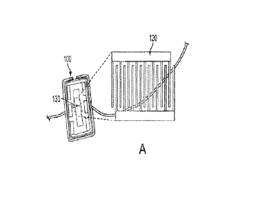
Referring now to FIG. 1A, there is shown a conventional, commercially
available
PARS 433.92 surface acoustic wave (SAW) resonator integrated circuit exposed
in top view
to show an electrode array portion 130 used according to FIG. 2A. In blow-up
form, the
electrode array appears as electrode array 120 as comprising a plurality of
uniformly spaced
fingers from first and second parallel electrode conductors. The structure of
the electrode array
may be better seen in the micrograph of FIG. 1B where each conductor (of
aluminum) resides
on a quartz/glass substrate. As will be further discussed herein, other
conductive metals and
substrates known in the art may be used to construct suitable electrode
arrays. Each finger
appears to have the same width, between 0.5 and 100 microns (for example,
between 1 and 3
microns), or 1.7 microns in particular and has the same spacing or separation
from one another,
in a range of .5 and 100 microns, also, preferably, between 1.0 and 3 microns,
or about 1.6
microns in spacing. A predetermined voltage in a range, for example, between
approximately
5 mVrms and 10 Vrms (preferably between 10 mVrms and 1 Vrms) or, for example,
between
100 and 500 mVrms is applied, for example, at a predetermined frequency in a
range, for
example, between as low as 20 Hz (preferably, 1 kHz) and 5 MHz and 1 kHz to
200 kHz in
particular for approximately one to ten minutes, for example, two to three
minutes, to induce
ACEK effects.
To assemble a complete system, one may incorporates a board-level signal
generator
with the electrode array (for example, to generate a 100 mv, 100 kHz signal
once a serum
sample is deposited), an impedance or capacitance read-out device, a
microcontroller as an
intelligent interface to the impedance/capacitance readout and a display read-
out. As
determined from tests described below, the predetermined value of signal
applied may range
from 5 mVrms to ten Vrms (preferably 10 mVrms to one Vrms) and at a frequency
between
20 Hz (preferably 1 kHz) and 5 MHz.
Construction of a detection test kit and the application of serum thereto is
provided by
the flowchart of FIG. 2A. In a first step 210, one coats the surface of an
exemplary electrode
array or integrated circuit array portion with a bacterial antigen (for
example, an extract of
Mycobacterium avium subspecies paratuberculosis for Johne's disease or M
tuberculosis for
human tuberculosis, antibody against PAG for pregnancy, or antibody against
pathogen for
mastitis). At step 220, one blocks the surface with a blocking buffer reagent.
One such
blocking agent that may be used comprises a phosphate-buffered saline (pH 7.0)
containing
.05% Tween20 and 10% SuperBlock blocking buffer available from Thermo Fisher
Scientific
of Rockford, IL. The pH level may be, for example, between 2.0 and 11.0 with
7.0 preferred.
CA 2988297 2017-12-11
Other blocking agents known in the art may be used. One may wash the uncoated
surface with
a wash such as phosphate buffered saline Tween (PBST) or other suitable wash.
The electrode
array apparatus may also take the form, for example, as seen in FIG. 10 in
cross-section: a
silicon (Si) substrate or wafer is provided with an electrode array deposited
by conventional
evaporation/sputtering in gold/titanium, gold/chromium, aluminum, copper,
silver or other
conductive material with a blocking layer on top and an antigen coating layer
between. The
electrode array chip is connected to a signal generator chip, a
microcontroller and a display
read-out before sample loading in one embodiment. For bio-particles with
pronounced DEP
responses (i.e., obvious attraction or repulsion to electrodes by a selected
electrical signal, such
as DEP responses of cells), by the choice of electrical signal frequency and
magnitude, selective
trapping/detection and improved selectivity may be realized. In some cases,
surface
functionalization may not be needed, and the electrodes can be reused without
washing, etc.
Next, a serum sample (a biomarker) is loaded at step 230, for example, by
dropping
from a pipette onto the coated surface of the electrode operating at a given
millivolt level and
frequency signal as discussed below. In testing, blind and other tests were
conducted which
would result in disease positive or disease negative results. As discussed
herein, at step 240 a
change in capacitance (or a change in impedance) results over time as
antibodies in the serum
bind with the coated antigen layer under test with the given signal. The serum
may be formed,
for example, from a selected body fluid, for example, milk from lactating
female animals,
blood, saliva, sweat and urine, depending on the application of the
impedimetric sensor (lab-
on-a-chip).
Once the electrode array chip is used, it may be washed and be reused with the
same
signal generator, microcontroller and display. The washing may, for example,
comprise use of
an avidin (glycoprotein)-biotin interaction or a biotin/streptaviden
interaction in conjunction
with a sodium hydroxide (NaOH) solution or a potassium hydrochloride/sodium
hydroxide
(KOH/Na0H) solution or other washing solution known in the art to clean off
the
antigen/coating so the electrode array may be reused.
In commercial production, it is expected that an integrated circuit may be
distributed
with an on-chip signal generator and electrode array exposed with an antigen
coating already
applied and blocked with the reagent. Alternatively, antigen and coating may
be applied on
site, blocked, the lab-on-a-chip used once, washed and then reused until it
becomes ineffective.
In one embodiment, the electrode array may comprise a separate chip that may
be easily reused
and replaced, for example, if its effectiveness decays after multiple uses and
washings. As will
16
CA 2988297 2017-12-11
be discussed further herein with respect to FIG. 2B, a system may comprise a
microcontroller,
a multiple sample array, a multiplexer, a signal generator and a connector to
a personal
computer or communication devices for communication of results to remote
laboratories or
disease centers or other remote facilities. In this example, the integrated
circuit will be ready
for loading of a plurality of samples which may be tested simultaneously. As
many, for
example, as twenty samples may be tested simultaneously with a like number of
electrode
arrays deposited on the same substrate. The entire system may be constructed
as portable and
useable in the field (not at a laboratory) such as at a dairy or cattle farm
or even in the home.
Results are available in minutes rather than hours as with a laboratory ELISA
(enzyme-linked
immunosorbent assay) test. Also, from the testing conducted thus far, only
approximately two
micro-liters of serum sample is required at a given concentration as will be
discussed further
herein to provide satisfactory detection. Consequently, many samples may be
tested
simultaneously on the same lab-on-a-chip. Such an amount of serum can be
readily obtained
from a human or animal body fluid (milk, blood, urine, saliva, ...) sample
without any need for
using a centrifuge.
FIG. 2B is an exemplary circuit block diagram of a multiplex electrode array
in
combination with a signal generator, a controller (computer processor and
memory) and display
for field detection of physiological conditions and infectious diseases such
as the bacterial
diseases Johne's disease and tuberculosis. In particular, the apparatus of
FIG. 2B comprises a
multi-sample holder 565 which may comprise a plurality of electrode arrays of
FIG. 1A or a
lab-on-a-chip as per FIG. 9 where there may be multiple electrode arrays for
receiving multiple
biological specimens for testing simultaneously (three shown). A signal
generator 570 is
shown connecting the control unit, preferably a microcontroller 554 known in
the art including
on-board data memory (not shown) to the multi-sample holder 565. The line from
controller
554 to signal generator 570 represents a control signal line indicating a
predetermined signal
or voltage level and a predetermined frequency so that signal generator 570,
in response, will
output a signal according to a user signal selection. The user selected signal
values of voltage
and frequency may be input from a personal computer (including a keyboard) or
other
intelligent device such as a pad computer or intelligent telephone and stored
in microcontroller
memory or external memory not shown. Microcontroller 554 also connects to
multiplexer 562
which is connected between impedance readout circuit 556 and multi-sample
holder 565 via a
buffer circuit 558.
17
CA 2988297 2017-12-11
On the left side of FIG. 2B, there are shown a connection to a personal
computer, for
example, a USB port, or to a storage memory card. The personal computer may
receive data
from microcontroller 554 and be used to retransmit the data via a
communications port and
network to disease control agencies, an external laboratory or anywhere that a
user may wish
to send the data. A start button is used to start a testing or multiple
simultaneous sampling of
tests, for example, once biological samples are loaded in the multi-sample
holder 565.
Detection/diagnosis may be performed in three steps. Step 1: When start is
pushed, a control
signal is sent to the controller 554 to activate multiplexer 562 and impedance
readout chip 556
to obtain multiplex readouts via the impedance readout line from the sample
holder 565 to the
impedance chip 556. The impedance chip 556 reports the capacitance/impedance
value as a
signal or plurality of signals, one for each sample, to controller 554,
setting the initial
capacitance/impedance values for the electrode array(s). Step 2: The
controller 554 activates
signal generator 570 to apply a signal of selected magnitude and frequency to
sample holder
565 for a predetermined period (for example, less than ten minutes), which is
meant to induce
ACEK effects to enhance the deposition of macromolecules/bioparticles onto the
electrode
surfaces. Step 3: The controller 554 again activates multiplexer 562 and
impedance readout
chip 556 to obtain multiplex readouts via the impedance readout line from the
sample holder
565 to the impedance chip 556, which provide the end state of
capacitance/impedance values
after the predetermined period lapses. The
impedance chip 556 reports the
capacitance/impedance value as a signal or plurality of signals, one for each
sample, to
controller 554. An LCD or other display 552 may provide a read-out of sample
data, for
example, in capacitance or impedance value at pre-selected time intervals over
the
predetermined period for the particular application of the lab-on-a-chip.
These periodic values
may be temporarily stored in memory of microcontroller 554 (not shown) along
with control.
The personal computer may be used to provide a graphical indication of
capacitance or
impedance change over time in comparison with control or other concentrations
and the like as
per the several figures provided herein.
Referring now to FIG. 2C, there is shown a complete kit for a lab-on-a-chip
embodiment comprising, for example, pipette 510 for dropping
blood/milk/saliva/urine or
other biological sample on to an array 530, which may be one of, for example,
eight arrays that
may be attached via an interconnector 525 to a slot of the kit 515. The kit
515 may connect
via standard connector cable to a port of an intelligent telephone 520 for
remote transmittal of
data.
18
CA 2988297 2017-12-11
Per FIG. 2D, there is shown an exemplary farm application where a
diagnostician takes
the kit of FIG. 2C to a cowshed, drops some blood/milk/saliva/urine or other
biological sample
on a pre-coated surface of an array of FIG. 1A, 9 and then may store the data
locally on an
exemplary plug-in memory or use an intelligent device 520 or personal computer
for data
analysis or remote transmission to a laboratory or disease control center or
other remote
location.
Referring briefly to FIG. 3A, negative and positive dielectrophoresis is shown
by way
of example acting on a molecule acting within an electric field caused by the
applied electrical
signal at a selected voltage and selected frequency. Referring now to FIG. 3B
which shows
AC electrokinetics in larger scale and with reference to a coated electrode
array of a given
geometry, molecules are shown at a surface velocity field in meters per
second, the arrows and
streamlines showing the velocity fields from the phenomenon.
Example 1 ¨ Johne's Disease
Referring now to FIG. 4, there are shown blind test results for Johne's
disease
comprising twenty samples, ten negative and ten positive, with the change rate
in capacitance
per minute shown. The minimum negative result had a value of -8.4539 and a
maximum result
of 8.2321% change in capacitance per minute. The positive test results show a
marked
difference with a minimum of -15.0843 and a maximum negative of -65.0035%
change in
capacitance per minute. There is a clear demarcation between a positive and a
negative test at
approximately -11%. The average is also shown for negative at -1.28953
compared with -
36.14971, again showing a clear demarcation line between positive detection
and negative
testing. Blind tests for Johne's disease were even run by a different student
performing tests
of twenty samples with similar results: -5 to +5% per minute for negative
versus -20 to -30%
per minute for positive detection.
Referring now to FIG. 5A, there is shown a graph of normalized capacitance
change of
positive, negative sera for diagnosis of Johne's disease, with the buffer
solution as the control
sample (1:10 antigen and 1:20 antibody serum concentrations). The data was
taken with an
electrical signal applied to the electrode array at a selected magnitude of
500 mVrms and a
selected frequency of 100 kHz. The duration of the tests is shown as running
for 200 seconds,
or just over three minutes. Test results (negative/positive) compared to
control may be seen in
about one minute or less compared with laboratory testing. FIG. 5C is similar.
What is shown
in FIG. 5C is that the serum concentrations may be varied from 1:1 to 1:80
without the
19
CA 2988297 2017-12-11
measured capacitance/impedance over time as displayed in graphical form
running into a
control level. Concentrations of 1:120 to 1:200 are too weak to distinguish
from control. FIG.
5B is a graph of serum concentration versus the % change rate of capacitance
for Johne's
disease at 1:80 and an applied signal of 100 mV at 100kHz frequency for the
predetermined
test period, in this application, approximately 120 seconds or two minutes
with the lab-on-a-
chip of FIG. 1. Improved results are obtained from the lab-on-a-chip of FIG. 8
as will be
discussed herein. FIG. 5D provides a linear bar graph showing negative test
results versus
positive test detection, capacitive change rates for Johne's disease sera in %
change per minute
versus the ten negative and positive results showing that Johne's disease
detection results with
clear threshold analysis.
Chip to chip reproducibility was tested by using the same test sample on five
different
coated electrodes. All five coated chip samples tested at a similar capacitive
change rate for
the same serum sample, between -20% per minute and -28% per minute. Serum to
serum
reproducibility was also tested using different serum samples for Johne's
disease. The ten
positive samples were tested on ten chips and the range in results was between
-20 and -28%
change in capacitance per minute.
Example 2 - Tuberculosis
Eleven human tuberculosis samples were tested via the method of FIG. 2, six
positives
and five negatives. Each sample was tested twice. Sample 1 exhibited a change
in capacitance
of 39.0679% over time in a first test and the second test of the same sample
at 14.3615% for
an average value of 26.7147% resulting in a conclusion of a positive test for
disease. A value
of 25 was determined to be an appropriate threshold. Other average positive
results included
42.89935, 45.7834, 71.02315 and 92.9081. These compare with negative average
results less
than the 25 threshold of 21.95305, 21.12935, 11.1021, 9.37895 and 8.49295.
Referring to FIG. 6, the human tuberculosis test results are compared to
results using
ELISA ¨ negative and positive results are shown whereby it may be seen that
the present test
process and ELISA provide similar results. Also, the human tuberculosis test
results were
compared where a readout of impedance Z change percent over time was taken
versus a read-
out of capacitance C over time with equivalent results. In other words,
impedance over time
may be equivalently measured over time to capacitance.
Referring to FIG. 7A, there is shown limit of detection graph results for a
100 mVrms
signal applied at 100 kHz and a predetermined period duration of two minutes
in this
CA 2988297 2017-12-11
tuberculosis application versus the change rate in % per minute for control
versus various
concentrations of micrograms per milliliter, the object being to determine the
limits of serum
concentration. As can be seen, antibody at concentrations of a range from 1 to
10 p.g/mL result
in clear differentiation compared with a control. A concentration at .1 ug/mL
might be
considered by some to be acceptable.
Now bovine tuberculosis test results will be discussed where ten negative and
ten
positive (total of twenty) badger tuberculosis samples were tested and
capacitance rate of
change over time measured.
A table is provided below showing the results:
Table 1
Sample No. dC/dt Conclusions from Results of
ELISA
Capacitance Measurement
N1 -31.2174
N2 -1.2917
N3 4.6227
N4 -18.1005
N5 -4.6286
N6 -16.4941
N7 -4.9776
N8 -3.3192
N9 -3.2161
N10
P1 -21.6996
P2 -18.8937
P3 -24.9467
P4 -12.544
P5 -15.9398
P6 -19.0317
P7 -26.0158
P8 -38.8778
P9 -25.838
P10 -19.0333
Buffer control .8837 N/A N/A
From the above table, it may be seen that three samples tested positive that
should have
tested negative out of twenty samples total in comparison with ELISA results.
Nevertheless,
the bovine tuberculosis tests for the badger samples demonstrated 85%
accuracy. It is believed
that the improved electrode array of FIG. 9 would provide improved results.
21
CA 2988297 2017-12-11
Referring now to FIG. 7B, there is shown a graph for badger tuberculosis
diagnosis on
the SAW resonator electrode array of FIG. 1 with an antigen 1:10 concentration
and a serum
1:20 concentration for a 100 mV per 1.1 in voltage drop signal applied for
120 seconds and
frequency varying from 1 kHz to 5 MHz. From an analysis of the graph, one may
conclude
that 10 kHz to 30 kHz is a preferred frequency range to read the change in
capacitance over
time data. Similar testing was performed for detection of Johne's disease and
will now be
discussed with reference to FIG. 8.
Referring first to FIG. 8A, there is shown a graph of Johne's disease
diagnosis on the
SAW resonator electrode array of FIG. 1 with a M paratuberculosis (MAP)
antigen 1:10
concentration and a serum 1:20 concentration with an applied voltage of 100mV
per 1.1 meter
over a predetermined duration in this application of 120 seconds or two
minutes. From an
analysis of the graph, one may conclude that approximately 10 kHz to 100 kHz
is a sensitive
frequency range to read the change in capacitance over time data. In FIG. 8B
and 8C, the
applied signal and concentrations were not changed but FIG.'s 8B and 8C
represent a graph for
five biomarker samples and their average for change in capacitance data over
time versus
frequency of applied signal while FIG. 8C provides similar results for a
change in impedance
data over time versus frequency. Tests were conducted from approximately 40 Hz
out to 6
MHz in FIG.'s 8B and 8C. From FIG. 8B, one may conclude that 1 kHz to 10 kHz
is a sensitive
frequency range to read capacitance while from FIG. 8C, one may conclude that
1 kHz to 50
kHz is a sensitive frequency range to read impedance change data over time.
Consequently, to
read either capacitance or impedance data, from FIG.'s 8B and 8C, one may
conclude that an
applied signal be in the range of 1 kHz to 50 kHz.
FIG.'s 8D and 8E also represent graphs of change in capacitance over time and
change
in impedance over time data versus frequency of applied signal for detection
ofJohne's disease
using the circuit of FIG. 1 and the same antigen and serum concentrations. The
frequency
range tested is again from about 40 Hz to 6 MHz. An analysis of FIG. 8D
suggests that 10 to
100 kHz is a sensitive frequency range for applied signal to read capacitance
data while FIG.
8E suggests that a lower frequency range of 1 kHz to 10 kHz is a sensitive
frequency range for
applied signal to read impedance data.
The results discussed above for bovine tuberculosis and Johne's disease and
for bovine
tuberculosis employed ethanol extracts of Mycobacterium bovis and M
paratuberculosis using
22
CA 2988297 2017-12-11
methods described in U. S. Patent No.'s 7,422,869 issued Sept. 9, 2008 and
7,713,715 issued
May 11, 2010 to inventor S. Eda and to C. A. Speer of the University of
Tennessee.
Alternative Electrode Array with Improved Performance
FIG. 9A provides a micrograph view of an electrode array constructed on a
substrate
which provides improved results over the conventional electrode array of FIG.
1. A substrate
may be as large as ten centimeters in diameter and comprise twenty electrode
arrays for
receiving biological test samples. As briefly described above, the electrode
array of FIG. 9A
provides a substrate of silicon and is constructed using well known photo-
lithography processes
to provide a repeatable pattern of fingers and spaces between the fingers and
as many sample
receiving locations as desired keeping in mind a one or two milliliter sample
deposit (even
microliter deposit depending on concentration level). FIG. 9B provides a
micrograph showing
an interspersed 5, 5, 25, 25 micron pattern that is repeated in the electrode
array depicted in
FIG. 8A. A first electrode is shown having a width of 25.1876 tin. A space is
then provided
of width 5.140960 tm. The next conductor has a width of 5.497225 pm. The final
separation
before the pattern repeats is 25.09273 [im. Note from FIG. 9A that a plurality
of electrode
arrays may be distributed on the surface of the same chip for receiving and
testing multiple
samples simultaneously. Other electrode configurations may include pin-line
coplanar
electrodes and face-to-face patterned electrodes. Microelectrode designs that
produce non-
uniform electric fields may be implemented as a laboratory on a chip. An
electrode mesh
formed as a capacitor will be discussed with reference to FIGS. 19A-19D and a
further
electrode array will be discussed with reference to FIG. 23.
FIG. 10 provides a drawing similar to FIG. 3B showing how the electrode array
may
provide improved binding results between an antigen/antibody against pathogen
coating layer,
invoking long range AC electrokinetic microflows. The electrode array may
comprise a
substrate of silicon Si 905. The 5, 5, 25, 25, 5, 5, 25, 25 finger/space
pattern are repeated across
the substrate whereby +Vcoswt, ¨Vcoswt, +Vcoswt and ¨Vcoswt are generated by
the applied
electrical signal of given magnitude and frequency. An antigen/antibody
against pathogen
coating layer 920 is shown above with the antigen/antibody against pathogen
appearing as Y
shaped-receptors for binding or not binding molecules by AC electrokinetics.
Molecules of
the antigen/antibody against pathogen coating layer are shown moving toward
the five micron
spaces between the five micron fingers and the 25 micron fingers and move away
from the 25
micron spaces and then back again. From the design of FIG. 9 and in comparison
with the
design of FIG. 1, it may be concluded that a range in finger values may be
successful in testing
23
CA 2988297 2017-12-11
for bacterial diseases between one and perhaps 100 microns. Similarly, the
range in spacing
between fingers may be between a range of from one and perhaps 100 microns
with successful
test results. While gold/chromium was used for the composition of the
electrodes, other
conductive metals may be used to advantage such as gold/titanium, gold,
silver, aluminum and
copper. Also discussed subsequently herein is the effectiveness of the
application of a coating
versus no coating of the electrodes.
In practice, twenty Johne's disease tests were performed ¨ ten negative and
ten positive
as before with the electrode array of FIG. 1 with the following results. For
testing negative,
the range was between -2.6356 and +.7537% change. For testing negative, the
range was
between -52.3152 and -83.8032% change. These ranges demonstrate a greatly
improved
differentiation between capacitive change rates between the micro-fabricated 5-
5-25-25 chip
and the commercially available electrode array for Johne's disease. The
applied signal in these
tests was at 500 mV and 100 kHz.
FIG. 11 provides a graphical example of the improved negative/positive
differentiation
between capacitance rate of change in % per minute for ten negative and ten
positive samples
of Johne's disease showing the dramatic differentiation between results.
FIG. 12 provides a graph of capacitance change rate in % per minute versus
concentration in micrograms per milliliter to show the limits of detection
using the chip of FIG.
9. As seen in the graph, concentrations as low as .01 ug per mL demonstrated
acceptable
results at 500 mV signal and 100 kHz signal frequency.
FIG. 13 provides a graph of capacitance change in % per minute versus
concentration
in nanograms per milliliter. The signal strength is raised to 1 Vrms and an
acceptable level of
detection is seen from the graph at .5 ng/mL concentration.
FIG. 14 provides a further limit of detection test on the wafer of FIG. 9 for
a
concentration of 100 nanograms per milliliter and an applied signal at 500 mV
per five microns
of electrode finger where capacitance change over time is graphed versus
frequency of applied
signal from 10 kHz to 10 MHz. The tests were conducted over three hundred
seconds (five
minutes) over a frequency range from about 40 Hz to about 6 MHz. From an
analysis of the
graph of FIG. 14, one may conclude that a frequency range of from 10 to 100
kHz is a sensitive
frequency range for reading the capacitance change over time data for the
wafer of FIG. 9
which compares favorably with the sensitive frequency range for the SAW
electrode array of
FIG. 1.
24
CA 2988297 2017-12-11
Example 3A ¨ Pathogen Detection (Mastitis)
Referring now to FIG.'s 15 through 19, pathogen detection for mastitis will be
discussed wherein milk samples may be taken from lactating animals.
Streptococcus uberis is
a species of Streptococcus. Protein G is an immunoglobulin-binding protein
expressed in
group C and G Streptococcal bacteria much like Protein A but with differing
specificities. It is
a 65-kDa (G148 protein G) and a 58 kDa (C40 protein G) cell surface protein
that has found
application in purifying antibodies through its binding to the Fc region.
Protein G is used for
preparation of each of the experimental group and control group specimens used
in blocking
of the lab-on-a-chip and bacteria shown in FIG. 15.
Referring to FIG. 15, two negative control groups and one experimental group
were
involved in pathogen detection. Protein G, per FIG. 15, may be incubated at a
concentration
of ten micrograms per milliliter and an amount of two milliliters in a humidor
overnight to use
in coating an electrode array as described above. In the area identified
Block, control (no
serum), Buffer B is shown at .1x concentration in an amount of two microliters
for one hour.
The experimental blocking solution may contain serum diluted 1:10 in Buffer B.
The array
was washed with PBST at .lx concentration using two microliters twice. The
Bacteria portion
of FIG. 15 comprises S. uberis bacteria at lx1 07 cell count (the same cell
density per milliliter
of bacteria that is reached in milk bacterial counts) using two microliters in
.1x PBS solution
as the experimental group. The control, no bacteria, may be PBS at .1x
concentration and two
microliters.
Three frequency sweeps were conducted for pathogen detection per FIG. 15.
Sweep 1
was at a signal magnitude of 5 mV between 40 Hz and 6 MHz for one second.
Sweep 2 was
at a signal magnitude of 100 mV and the sweeping frequency taking 201
measurement points
was at 5 kHz, 10 kHz, 20 kHz, 50 kHz, 100 kHz, 300 kHz, 500 kHz, 800 kHz, and
1 MHz. A
third frequency sweep (Sweep 3) was between 40 Hertz and 6 MHz for one second
(similar to
Sweep 1) at 5 mVrms. Sweep 2 was the experimental sweep to test for
appropriate frequency
and maintain a change in capacitance over time demonstrating diagnosis of
bacterial disease
(mastitis) versus control change in capacitance by comparing bacterial
solution binding of the
pathogen detection coating at different frequencies to control groups. These
results are
demonstrated in FIG. 16.
Referring now to FIG. 16A, there is shown a graph of percent change in
capacitance
over time for control group serum of .1x concentration PBS with no bacteria,
Sweep 2 results
CA 2988297 2017-12-11
only. The negative control group with no bacteria demonstrates a maximum
percent change in
capacitance over time when the signal is at 400 kHz. At 800 kHz and at 300 kHz
the percent
change in capacitance over time is slightly reduced. At 50 kHz, the percent
change in
capacitance over time is decreased more still.
Referring now to FIG. 16B, there is shown a graph of percent change in
capacitance
over time for negative control group solution with no specific serum antibody,
Sweep 2 results
only. The negative control group demonstrates a maximum percent change in
capacitance over
time when the signal is at 800 kHz. At all other frequencies in the sweep, the
percent change
in capacitance was significantly less (better).
Referring now to FIG. 16C, there is shown a graph of percent change in
capacitance
over time for the bacterial solution (S. uberis/mastitis) binding to the
antibody serum, Sweep 2
results only. The bacterial solution group demonstrates a maximum percent
change in
capacitance over time when the signal is at 300 kHz and again at 50 kHz. At
100 and at 200
kHz, the percent change in capacitance was lower.
The results are summarized in FIG. 16D, which is a combined graph showing the
results
of FIG. 16A, B and C superimposed on one another where the gray scale shows
that for each
frequency, the percent change in capacitance over time is shown in the order
of no serum, no
bacteria and bind from left to right. At all frequency points in FIG. I 6D,
binding exceeds serum
and bacteria control except the frequency results for 800 kHz. One may
conclude from the
graph that an applied signal between 50 kHz and 4000 kHz at 100 mV for sixty
seconds (Sweep
2 signal parameters) appropriately distinguish S. uberis binding from negative
controls. FIG.
16E provides a chart of all data taken and calculated standard deviations for
all points.
Referring now to FIG. 17, there is shown a graph calculated by Sweep 3 ¨ Sweep
1 per
sixty seconds where the percent change in capacitance over time curves at nine
different
frequencies show the averaged changes from reactions. From the graph, one may
conclude
that between 40 Hz and one kHz is a sensitive frequency range to read percent
change in
capacitance over time by the differentiation of experimental group (binding)
versus either
negative control groups (no serum or no bacteria) over that range.
In FIG. 18A, 18B and 18C, there are shown respective graphs of percent change
in
capacitance over time calculated by Sweep 3 ¨ Sweep I per sixty seconds where
the percent
change in capacitance over time curves were studied for signals at 50 kHz, 150
kHz and 300
kHz, the preferred signal frequencies calculated from FIG. 16D. It may be
concluded from this
26
CA 2988297 2017-12-11
graph that there is more pronounced differentiation when the capacitance or
impedance percent
change is taken at lower frequencies such as between 40 Hz and two kHz. Note
that between
these frequencies, experimental group (binding), the lowest curve for 300 kHz
(FIG. 18C),
provides significantly greater percent change in capacitance than negative
control groups no
bacteria or no serum at 300 kHz. Above ten kHz, experimental group (binding)
and no bacteria
and no serum become close together so that binding may not be easily
distinguished. Note also
that between these frequencies, binding, the next to the lowest curve, at 50
kHz applied
frequency, distinguishes from the bacteria curve just above at a range of
frequencies, between
100 Hz and one KHz, and the differentiation is not as pronounced but then
moves apart again,
for example, at 10 kHz. The 150 kHz set of FIG. 18B appears to demonstrate a
clear detection
of binding across the entire frequency spectrum. In summary, it appears from
this graph that
differentiation of mastitis/S. uberis is preferred at a 150 kHz or 300 kHz
signal frequency and
between 40 Hz and ten kHz. The bacteria may be distinguished with a sixty
second or one
minute test at 100 mV applied signal on an electrode array coated as
described.
Example 3B ¨ Somatic Cell Count (Mastitis)
FIG. 19A provides a view of a substrate and overlaying electrode meshes of
differently
sized openings for white blood cell count, for example, for detection of
mastitis in cattle. The
somatic cell count measures the number of somatic cells (immunocytes, like
neutrophiles) in
milk samples According to FIG. 19A, an electrode array comprising atop
electrode mesh with,
for example, a one hundred meter opening may be overlaid and spaced from a
bottom
electrode mesh with, for example, a smaller fifty meter opening, the object
being to permit
true biomarker sample to pass through the top and bottom electrode meshes to
reach, for
example, a sample reservoir or an opening (not shown) to allow the sample to
be collected
and/or cleaned from the array, such that the embodiment of FIG. 19A promotes
an opportunity
to detect mastitis via somatic cell count via change in capacitance as
described above. In
practice, the top electrode may have between a 10 and 500 micron opening
(preferably between
50 and 150 micron opening) and the bottom electrode between 5 and 150 micron
spacing
(preferably between twenty and eighty micron spacing) depending on the
lactating animal
under test, cattle, goat, sheep and the like. FIG. 19B shows a spacing between
the top and
bottom electrode meshes (two plates of a capacitor), the two meshes or grid
networks forming
a capacitor. As used herein and in the claims, a first "mesh" comprises a
network-patterned,
for example, rectangular network electrode comprising a first electrode array,
with or without
openings. The mesh underneath may likewise include or not include openings. In
other words,
27
CA 2988297 2017-12-11
a mesh may be solid. The second mesh is shown under the first mesh and
provided with a
spacing between the meshes to form a capacitor. In an embodiment of FIG. 19A,
a sample
passes through and reaches a reservoir. In alternative embodiments, a
patterned network mesh
may be a solid surface with no openings and the sample may rest on the top of
two meshes
forming a capacitor or pass through a top mesh to a solid bottom mesh. FIG.
19C provides a
diagram showing how a sample is dropped on the overlaying electrode meshes and
a particular
alternating current signal applied to the meshes. FIG. 19D provides a black
and white line
drawing of a photograph of the overlaying mesh electrodes on the substrate and
an expanded
view showing the overlaid electrode meshes of one embodiment.
Sample 3853 comprises, for example, a particle density of 1.92 x 10⁶ particles
per
milliliter and sample 4118 may comprise a particle density of 3.5 x 10⁶
particles per milliliter.
These samples comprise somatic cell (milk) samples taken from lactating
animals. FIG. 20A
provides a graph of resulting normalized capacitance over time (a one minute
test) showing in
FIG. 20A curves for cell fix (no cell), sample no. 3853 and sample no. 4118.
The experimental
method is exactly the same as was used for devices described above. The
capacitance of cell
fix (no cell) solution shown in boxes and of sample 3853 increased 5.469% and
1.13065% in
a one minute (60 second) test with an applied frequency of 100 kHz and a
voltage of 500 mV
of applied signal to the overlaid electrode mesh array of FIGS. 19A-19D. FIG.
2013
investigates levels of concentration of sample 4118 versus no somatic cells to
show that 100
dilute sample 4118 may detect mastitis versus no cell. The same scanning
voltage of 500 mV
and frequency at 100 kHz were applied. Pure 4118 showed a negative change in
capacitance
of -1.54% as was indicated in FIG. 20A at -.9%. On the other hand, 100 dilute
4118 showed a
positive change in capacitance of 2.15% and 10 dilute 4118 a positive change
in capacitance
of 1.27%. FIG. 20C shows a graph of somatic cell count over a five minute test
versus change
in capacitance over change in time. A strong correlation was observed between
the capacitance
change rate and somatic cell count in milk, demonstrating that this method is
useful for
diagnosis of mastitis. In the graph, y = -1.8741n(x) + 14.517 and R2 = 0.8763.
At a good cut-
off value of 200K somatic cells/mL, the sensitivity and specificity of the
test are calculated to
be 94.7% and 100%, respectively. The result was obtained in five minutes,
which is short
enough to be used in an in-line system and achieves high accuracy. Similar
results were
obtained in two other separate experiments. Shorter duration testing is
possible by changing
test parameters or by giving up some accuracy. In Europe, a somatic cell count
of 400k is used
for determining if milk is sellable; in the U.S., the somatic cell count value
for determining
28
CA 2988297 2017-12-11
sellable milk is 750k. These figures may be utilized in the respective
locations for a cut-off for
somatic cell count and achieve similar sensitivity and specificity.
Example 4A ¨ Pregnancy via anti-PAG antibody
FIG. 21 illustrates the steps of a process of preparing a SAW electrode array
of FIG. 1
for a pregnancy test utilizing a coating of a-PAG (anti-PAG antibody),
available from IDEXX,
for pregnancy detection. The first step is to treat the SAW array with protein
G at 10 grams
per milliliter in 1X PBS overnight in a humidor at room temperature. Then, the
array may be
washed once with 0.1X PBST. The a-PAG available from IDEXX is then loaded and
kept for
approximately one hour at room temperature. Again, the loaded array is washed
with 0.1X
PBST and then blocked with 0.1X B for approximately 30 minutes to an hour at
room
temperature.
Testing may comprise loading serum at 1:5 to 1:20 to optimize the dilution as
a positive
or a negative experimental group. Also, 0.1X buffer B may also be loaded as a
control group.
The sweep and data collection process may comprise applying about 5 mV at
between
forty Hz to 6 MHz for one second to initialize a value of capacitance over
frequency. Then,
the applied signal may be 100 mV at 100kHz for an approximately one minute
test recording
capacitance over time for control and real samples. A processor may then
calculate the change
in capacitance over time as a function of the initial capacitance sweep.
FIG. 22A and 22B respectively provide respective graphs of change in
capacitance
over time versus frequency of applied signal wherein it may be concluded that
a signal in the
range of 50 kHz and greater may be used to detect pregnancy and a summary of
five tests for
pregnancy, positive versus negative or buffer solution showing that pregnancy
may be detected
and are shown in summary form.
Limit of detection study of electrode array design
FIG. 23A provides a drawing of an interdigitated electrode array constructed
of first
providing a plurality of widely spaced electrodes and then for each wide
electrode a plurality
of very closely spaced electrodes to study the limits of detection of such a
constructed electrode
array. The purpose of the design and testing is to explore the limits of
detection of an array
structure comprising widely spaced asymmetric electrodes and wide electrodes
to attract
biomarker to a narrow plurality of parallel symmetric electrodes. The specific
dimensions of
a wide spacing of asymmetric electrodes reads from top to bottom: D1, the
width of a first
asymmetric electrode, is 22.89946 meters (approximately 20 microns); D2, a
first spacing
29
CA 2988297 2017-12-11
between interdigitated wide asymmetric electrodes is 9.159782 meters
(approximately 10
microns; D3, a wide spacing between asymmetric interdigitated electrodes of
29.31130
(approximately 30 microns) and D4, the width of the widest asymmetric
electrode being
59.53359 meters (approximately 60 microns). Then follows a plurality of
symmetric narrow
width electrodes narrowly spaced and shown in particular detail in a blow-up
diagram at the
bottom of FIG. 23A. The blow-up shows the flowing spacings and widths of
symmetric
electrodes: D3 the overall width of the plurality of symmetric electrodes is
approximately 30
meters; D4 is the spacing between symmetric electrodes of approximately 1.5
meters and
D2 is the width of one symmetric electrode or approximately 2 meters. The
limit of detection
tests on the new electrodes comprises forming an electrode pattern as a
combination of
symmetric and asymmetric interdigitated electrodes whereby the asymmetric
electrodes may
help to generate flow so that more particles are attracted to the symmetric
electrodes where
they may bind. The asymmetric pattern is roughly 10/20/30/60 and the symmetric
pattern is
roughly 1.5/1.5/1.5/1.5 (or 2/2/2/2 or an interlaced 1.5/2 pattern).
FIG. 23B is a diagram showing the simulated attraction and flows of particles
under
the influence of electrokinetic phenomenon to be attracted to the widely
spaced electrode and
then bind to the very closely spaced electrodes. The arrows represent flow and
the lines show
convection of particles towards the designated area determined by the widely
spaced
electrodes, where the narrowly spaced electrodes are located. FIG. 23C is a
diagram showing
improved detection of concentrations of biomarker particles at, for example, 1
ng per mL, 2 ng
per mL and 5 ng/mL. The change of capacitance is seen to double from 1 ng/mL
concentration
to 2 ng/mL concentration and then double again at 5 ng/mL concentration where
the test was
conducted at an applied signal frequency of 57.5 kHz. Control 1 and 2 are also
indicated as
exhibiting positive changes in capacitance (as does a small concentration of
.5ng/mL. Again,
the limit of detection experiment appears to demonstrate that a combination of
narrow and wide
interdigitated electrodes is preferred to provide an attraction of particles
to the symmetric
electrodes for binding.
As the above results suggest, the several embodiments of a lab-on-a-chip
coated as
described and so prepared for receiving a signal of given magnitude, frequency
and over a short
period of time, such as less than ten minutes, may very likely be used for
rapid, in the field or
bed-side diagnosis of a number of infectious diseases (via antigen, pathogen,
abnormal white
cell count) and protein detection, for example, for physical conditions such
as pregnancy.
Example 4B ¨ Small Molecule Detection
CA 2988297 2017-12-11
For small molecule detection, of which progesterone is but one example, the
procedure
for lab-on-a-chip construction and testing is very similar to that described
above. Progesterone
level may be a means of testing for pregnancy. The 5/5/25/25 meter electrode
on a wafer was
utilized. However, the impact of treatment with 3-aminopropyl-triethocysilane
(APTES) was
analyzed to determine if such treatment might have some impact on change rates
of capacitance
over time.
In particular, for small molecule detection, for example, progesterone, anti-
progesterone polyclonal antibody was added in 0.1XPBS on to the electrode
surface and
allowed to incubate, for example, overnight in a humidor (for example, 4-8,
preferably 6 hours
is preferable). Once incubated, the electrode may be washed, for example, with
PBS-T, for
example, three times. Blocking is then performed using 0.1X Buffer B for a
period in excess
for example, of thirty minutes to be sure the blocking is successful. Then,
the blocked electrode
with the anti-progesterone polyclonal antibody is washed with PBS-T, for
example, three times.
Testing was performed by adding different concentrations of progesterone using
plain
.1X Buffer B as a control starting at 1 ng per milliliter and increasing
concentrations of
progesterone to as high as 10,000 ng per milliliter in 0.1X Buffer B. In the
test at hand, three
chips were tested. Concentration level resulted in an increase from the
control of no change in
capacitance over time to about 4.2 dC/dt (%/min) and then to about 10.1 dC/dt
(%/min) for 10
ng per milliliter progesterone. For 10 ng/mL, the CV was 1.7%. Then, when
higher
concentration levels of progesterone were tested, for example, at 100
ng/milliliter or 1000
ng/milliliter, there was still exhibited a dC/dt %/min of test, but the level
reduced to about 2.5
dC/dt suggesting saturation for higher levels of progesterone.
As indicated above, APTES treatment was also attempted and the results were
interesting. Specifically, about 2v/v% APTES in ethanol alcohol was added and
allowed to
incubate at 63 C for about 4 hours, then washed with doubly distilled water
three times and
allowed to dry. An air gun may be used to speed drying. The APTES treated
surface dried
very quickly with the air gun, and no cluster formed when checked under a
microscope.
Then, 2.5% Glutaraldehyde solution was added and allowed to incubate for about
two
hours at room temperature. The electrode was then washed with double distilled
water three
times. The electrode was not allowed to dry before adding the progesterone ant-
body as
described above. Finally, one hundred mM ethanolamine solution was added and
allowed to
incubate at room temperature for 1 hr. The rest of the preparation for loading
with progesterone
31
CA 2988297 2017-12-11
was the same ¨ blocking with .1X Buffer B for longer than thirty minutes and
washing with
PBS-T.
Progesterone was added to the APTES treated chip in levels between 0 (control)
and 1
ng, .5 ng, 1 ng, 5 ng, 10 ng and 100 ng per milliliter concentrations in .1X
Buffer B.
Measurements are summarized in the table below where the dC/dt (%/min) was
performed at
100 kHz frequency and the voltage level was 500 mV:
Table 2
Concentration Without APTES With APTES
0 ng/mL control 1.2019 3.886
.5 ng/mL 2.5754 6.3182
1 ng/mL 2.989 9.7209
5 ng/mL 1.3632 6.2795
ng/mL 1.2909 5.1568
The test results with versus without APTES treatment tend to show that change
in
capacitance over time go up with APTES versus without and, for example,
between 1 ng/mL
versus 5 or 10 ng/mL seem to show a less drastic saturation, for example, from
9 to 6 to 5
versus without APTES, the 10 ng/mL result at 1.2909 is little distinguishable
from the control
at 1.2019. So it may be fairly concluded that APTES treatment as described
above may help
small molecule detection.
Example 5 ¨ D-dimer as an indicator of clotting
Emergency conditions may occur after surgery or during active life. D-dimer is
an
indicator of clotting. In the following series of tests, a PPy-coated
electrode was compared
with an un-coated electrode. Preparing the coated chip involved several steps.
The chip was
cleaned three times with 0.1M diabasic sodium sulfate. Then, the polymer
coating solution
was prepared by adding 70 liter of Pyrrole to 930 liter sodium sulfate to
make 0.1M
Pyrrole/0.1M sodium sulfate. The polymer was then electrochemically deposited
by loading
the 0.Im Pyrrole/0.1M sodium sulfate onto the 5/5/25/25 meter wafer.
Approximately 1.5 V
was applied for about five seconds at room temperature to deposit the coating
and the wafer
32
CA 2988297 2017-12-11
washed twice with PBS. To load or functionalize the Polypryrrole coated chip
surface with
antigen, anti-D-dimer antibody was loaded as 10 gram per milliliter in 0.1X
PBS and cured
for 30 minutes in a humidor at room temperature (humidor optional or if
needed). Then, the
chip was washed three times with PBST.
The test results occurred by loading D-dimer solutions with a control at no D-
dimer at
different concentrations in 0.1X Buffer B. 0.1X PBS was used as the test
solution. The
frequency range tested was between 40 Hz and 6 MHz.
The table below shows the detailed results on Concentration (/mL) for three
tests as the
test conditions were 500 mv (voltage), 100 kHz (frequency) and 1 minute
duration. Units for
results are dC/dt (%/min):
Table 3
Concentration(/mL) Test-1 Test-2 Average std
Pbs (control) 1.5896 3.4225 2.50605 .91645
0 pg 2.793 2.5786 2.6858 .1072
.1pg 7.8 .809 4.3045 3.4955
1 pg 4.904 7.8288 6.3664 1.4624
10 pg 25.0948 28.5901 26.84245 1.74765
100 pg 36.4224 47.1754 41.7989 5.3765
1000 pg 22.2459 5.7128 13.97935 8.26655
In D-dimer detection, it appears as if saturation was reached at approximately
100 pg.
The test successful test range appears to be between 10 pg and 100 pg with
1000 pg still
yielding satisfactory results in comparison with control after saturation is
reached.
33
CA 2988297 2017-12-11
A control test result is shown below where a sample was dropped directly on
PPy coated
electrodes without surface functionalization and blocking. The change rates
turned out to be
very small which tends to rule out the chance of mass non-specific binding:
Table 4
Sample dC/dt (%/min)
pg only 1.968
100 pg only 2.1729
10000 pg only 1.216
FIG. 24 A and B show test results by Nyquist plots of impedance versus
resistance with
the frequency range tested being 1 kHz to 110 MHz. The curves correlate well,
for example,
for 10 pg concentration per mL. which is demonstrated also by our test results
which suggest
that, for the moment, 10 to 100 pg may be our detection limit and results
above 100 pg exhibit
saturation.
Example 6 ¨ Sugar (Glucose Detection)
The 5/5/25/25 electrode embodiment was also used for testing for sugar,
glucose in
particular. A similar process was followed for loading and blocking the chip
for sugar testing.
For glucose, we used glucose oxidase, an enzyme, as the molecular probe that
was loaded on
the chip and blocked. The following table is used to show an optimization for
testing
frequency. As can be seen from the table below, a frequency between 50 and 100
kHz was
preferred:
Table 5
1 mg/ml .1 mg/mL 0 mg/mL
10 kHz -1.7146 3.5377 -2.1191
50 kHz -10.2018 -7.7705 -2.9972
100 kHz -14.9818 -10.4084 -3.3253
200 kHz -2.2687 0.9512 -4.4439
34
CA 2988297 2017-12-11
A table is also shown below wherefrom it may be determined that voltage level
was not
a significant factor in the testing. Tests were performed for voltage values
between 10 mV and
500 mV without the voltage level having much impact on results:
Table 6
mv 100 mv 500 mv
0 mg/mL -5.9452 -8.8171 -4.9855
.1 mg/mL -7.7512 -5.2861 -6.1618
1 mg/mL 4.9818 -6.0203 -6.3895
10 mg/mL -11.4325 -6.4134 -6.8759
5
The following table provides the test results for glucose detection where the
frequency
used was 100 kHz, the voltage was 500 mV and an Agilent device was used to
apply the voltage
at the test frequency chosen:
Table 7
Test 1 Test 2 Test 3 average std
10k pg -2.081 -2.091 -1.517 -1.896 .2679
1k pig -11.09 -12.01 -13.38 -12.16 .9409
100 pig .8471 -3.124 -5.293 -2.5236 2.5425
10 pig -5.868 -.3218 -2.795 -2.9953 2.2689
0 pg 6.9314 3.1267 -.6871 3.1236 3.1102
Saturation appears to have been reached at 1000 [Lg with the results shown as
dR/dt(%/min) where R is resistance. As indicated, glucose is but one example
of a sugar that
may be similarly tested. One suggested application of sugar detection, e.g.,
sucrose, is in the
detection of sugar in beer in addition to medical applications (e.g.,
glucose).
Example 7 ¨ Enzymatic Redox Reaction Detection
CA 2988297 2017-12-11
Enzymatic redox reactions have been used for diagnosis of diseases or
detection of
molecules in solution. An enzymatic redox reaction generally involves a
reaction between an
enzyme and a substrate, producing ions that change the conductivity of the
solution. The
change in conductivity may be detected electrochemically, for example, by
measuring a change
in a current flowing through the solution.
There are at least three different ways that enzymatic redox reactions may be
used for
diagnosis of diseases through electrochemical detection¨detection of a
substrate, detection of
an enzyme, and detection of a probe.
An example of substrate detection is using the diagnostic redox enzyme glucose
oxidase, which catalyzes conversion of glucose (substrate) to gluconolactone
while producing
hydrogen peroxide. The level of hydrogen peroxide can be electrochemically
measured as a
surrogate of glucose level in the sample. This reaction is the basis for
measurement of glucose
(substrate) level which elevates in patients with diabetes. Normal level of
glucose in blood is
5 mM and detection limit of glucose based on this principle is reported to
range from 1 nM to
25 M.
An example of enzyme detection is when lactate dehydrogenase (LDH), which is a
marker of general tissue damage, catalyzes conversion of aspartate to
glutamate. When
glutamate is converted to ketoglutarate by glutamate oxidase, hydrogen
peroxide is produced
as a side product and can be detected electrochemically as mentioned above.
Normal level of
LDH is 3 nM and detection limit of a commercial test is 30 pM.
As for probe detection, when a probe of a target analyte (such as aptamer) is
conjugated
with a redox enzyme inhibitor, such a conjugate inhibits reaction of redox
enzyme only in the
absence of the analyte, and, therefore, can be used to measure the level of
the analyte in a
solution. This can be used not only for disease diagnosis, but also for other
purposes such as
chemical contaminants in environmental samples.
These three concepts may be applied to the lab-on-a-chip for sensitive and
rapid
diagnosis. The lab-on-a-chip may detect a change in interfacial capacitance
due a change of
conductivity of the sample solution resulting from enzymatic redox reactions
close to the
surface of the electrodes. The electrode array may be functionalized/coated
with either linker
molecules specific to diagnostic redox enzymes (for enzyme detection) or redox
enzymes
themselves (for substrate or probe detection). A low AC voltage signal may be
applied to the
electrode array to induce ACEK effects that create convection of target
molecules (e.g.,
36
CA 2988297 2017-12-11
enzymes, substrates, and/or probes) towards the surface of the electrode
array, promoting redox
reaction catalyzed by enzymes captured by the linker molecules (enzyme
detection) or the
immobilized enzymes (substrate or probe detection). The redox reaction
specific to the
enzyme-substrate pair may be detected by measuring the change in interfacial
capacitance at
the surface of the electrode array.
FIG. 25A is a conceptual drawing illustrating the detection of redox enzyme by
AC
capacitive sensing. An antibody, appearing as Y-shaped receptors (i.e., linker
molecules) and
immobilized on the electrodes, captures a specific enzyme (shown as 0), which
then catalyzes
redox reaction with a substrate (shown as *) in the sample
solution/electrolyte. The reaction
happens at the electrolyte/electrode interface and can be detected by a change
in the interfacial
capacitance.
FIG. 25 B is a representative equivalent circuit of the 'electrolyte-
electrode' system of
FIG. 25A. A charge transfer resistance Rct and an interfacial capacitance Cint
may account for
charge transport at the electrode/electrolyte interface. In FIG. 25B, the
electrolyte resistance
is represented as Rfluid and the electrolyte capacitance as Cfluid. Enzymatic
reaction causes
charge transfer across the biopolymer layer on the electrode. Electrically,
this phenomenon
may be illustrated as Ret going down and Cint going up. By monitoring Cint,
the lab-on-a-chip
focuses on the process taking place close to electrode surface. As the
enzymatic reaction
continues, Cu-a increases continuously. Higher sensitivity is expected for
this method due to
enzymatic amplification and interfacial capacitance measurement.
The interfacial capacitance Cint is the indicator of the enzymatic redox
reaction. Cint is
indicative only of changes at sensor surface, as illustrated by the equivalent
circuit of FIG 25B.
As such, the detection is highly localized around the interface where enzyme
reactions take
place. The response is not an average of ionic environment between the
electrodes as with
conventional electrochemical detection. Consequently, using the lab-on-a-chip
to detect
enzymatic redox reactions is more sensitive. Additionally, the effect of
interferences in a
complex fluid mostly shows up through the fluid resistance Rflind. Such
interferences can be
easily eliminated when only Cint is measured. Consequently, high sensitivity
and specificity
are expected when using the lab-on-a-chip to detect enzymatic redox reactions.
The detection is done at a fixed frequency, which allows for simultaneous
induction of
ACEK convection of molecules (including substrates and products) and
interfacial capacitance
measurement. At frequencies commonly used for ACEK, the impedance may be
approximated
37
CA 2988297 2017-12-11
as a serial connection of Cmt and Rfluid, allowing for direct extraction of
Cmt without resorting
to complicated data processing or instrumentation.
Moreover, with a detection metric that uses a change rate of normalized Cmt,
baseline
drift or the need for a reference sensor/reference sample may be avoided,
greatly simplifying
the detection procedure and instrumentation. Requirements on instrument
precision may also
be relaxed, minimizing the effect of differences between sensors and allowing
the system to be
built at affordable prices.
FIG. 25C shows experimental results for substrate detection using electrodes
functionalized with an enzyme, for different concentrations of the substrate.
The substrate in
the solutions is Tetramethilbenzidine Dihydrochloride Dihydrate (TMB) (M.W.-
349.3, MP
Biomedicals, LLC, Cat. No.: 152116). The enzyme immobilized on the electrodes
is
Horseradish Peroxidase (HRP) (Thermo Scientific, No.: 31490). The electrode
surface was
blocked with 0.01% Triton for half an hour. The experiment was carried out
with a 20-kHz,
100-mV AC signal. FIG. 25C shows the normalized dC/dt recorded for 1 fM, 10
fM, 100 fM
and 1000 fM (1 pM) of TMB samples. As can be seen, the normalized dC/dt
increases
proportionally with the increase in substrate concentration.
Detection Amplification with Labeling Particles
The limit of detection (LOD) of the lab-on-a-chip has been found to be
dependent on
the size of the target molecules or analytes. Specifically, LOD decreases as
the size of the
analytes increases. For example, when testing specific proteins, which are
about 10 nm in size,
the LOD was about 1 ng/mL, while the LOD was about 1 pg/mL when detecting
virus particles
that are about 100 nm in size.
As such, the detection of small sample analytes may be amplified (i.e., the
LOD may
be decreased) by conjugating the small sample analytes with nano- to micro-
size particle labels
and then loading the conjugated sample onto the electrodes of the lab-on-a-
chip. The labeling
particles are functionalized with linker molecules specific to target analytes
prior to the assay.
A known concentration of labeling particles is mixed with the sample solution.
The mixture is
incubated for the labeling particles to conjugate with the target analytes.
The conjugated
sample is loaded onto the electrode for testing. The labeling particles may be
latex beads,
magnetic beads, or microorganisms such as virus, bacteria. FIGS. 26A, 26B, and
26C are
depictions of sample analytes, a labeling particle, and a conjugated sample,
respectively.
38
CA 2988297 2017-12-11
FIGS. 26D depicts a coated/functionalized electrode of a lab-on-a-chip. FIG.
26E
illustrates analytes, without labeling particles, binding to the coated
electrode. Here, the change
in impedance or capacitance of the electrode is due to the addition of the
analytes. Such a
change in capacitance may be small for diluted concentration of analytes. On
the other hand,
FIG. 26F illustrates conjugated samples binding to the coated electrode. In
this case, both the
analytes and the labeling particles contribute to the change in impedance or
capacitance, thus
amplifying the detection of the lab-on-a-chip.
The present lab-on-a-chip may also be used to detect enzyme levels in a manner
faster
than ELISA or other laboratory methods. Above, the enzyme, glucose oxidase was
discussed
for diagnosis of diabetes. Certain tissue cells (such as organ tissue cells)
contain characteristic
enzymes which enter the blood only when the cells to which they are confined
are damaged or
destroyed. One example of an enzyme that may be tested for in animal blood is
aldolase which
may be symptomatic of skeletal muscle damage at high serum levels in the blood
and
progressive muscular dystrophy. Also, aldolase levels may be slightly
increased in early stages
of viral hepatitis and advance prostate cancer (males). Creatine Phosphokinase
(CPK) is
another enzyme which may be measured by lab-on-a-chip from blood samples and
may be a
valuable for differentiating diagnostic information related to heart attacks
or indicative of
skeletal muscle damage. GGT is an enzyme symptomatic of obstructive diseases
of the biliary
tract and liver cancers. Lactic Dehydrogenase (LDH) can be further separated
into five
components or isoenzymes LDH-1, LDH-2, LDH-3, LDH-4 and LDH-5. Differential
levels
of these isoenzymes may be indicative of liver or muscle disease. An LDH-1
level higher than
that of LDH-2 may be indicative of a recent heart attack or heart injury.
Since total LDH level
rises within 24 to 48 hours after a heart attack, LDH level testing is a
useful tool for delayed
diagnosis of a heart attack. Other enzyme levels that may be tested for via
lab-on-a-chip
include Lipase for pacreatatitis, GOT for heart angina or liver damage
(including cirrhosis) and
biliary obstruction.
Testing of well water typically involves the testing for bacteria content, in
particular,
coliform and E. coli. The present lab-on-a-chip invention may find commercial
application for
well water testing for bacteria.
A list of infectious diseases that may be similarly diagnosed comprise HIV,
Hepatitis
B and C, SARS, Helicobacter pylori infections, Leprosy, Lyme disease,
Toxoplasmosis,
Newcastle disease, Foot-and-mouth disease, Porcine parvovirus, Pseudorabies,
Avian
influenza, Porcine Reproductive and Respiratory Syndrome, brucellosis and,
also, Crohn's
39
CA 2988297 2017-12-11
disease. Considerable evidence exists that MAP is also a causative organism of
Crohn's
disease in humans, and some MAP antigens, p35 and p36 in particular, were
found to be
reactive in a majority (95%) of Crohn's disease patients' blood samples as
reported by Ira
Shafran et al., September, 2002, Digestive Diseases and Sciences, pp. 2079-
2081. Also,
antibodies against Saccharomyces cerevisiae (ASCA/neutrophilic cytoplasm
(ANCA) are
known to be indicators of Crohn's disease and used in commercial immunoassay
kits available
from Orgentec and The Doctors Doctor. The ASCA/ANCA immunoassays are used for
differential diagnosis of ulcerative colitis and Crohn's disease with similar
symptoms.
Consequently, the present lab-on-a-chip embodiments may have application in
the diagnosis
of Crohn's disease in humans.
While various aspects of the present invention have been described above, it
should be
understood that they have been presented by way of example and not limitation.
It will be
apparent to persons skilled in the relevant art(s) that various changes in
form and detail can be
made therein without departing from the spirit and scope of the present
invention. Thus, the
present invention should not be limited by any of the above described
exemplary aspects, but
should be defined only in accordance with the following claims and their
equivalents.
In addition, it should be understood that the figures in the attachments,
which highlight
the structure, methodology, functionality and advantages of the present
invention, are presented
for example purposes only. The present invention is sufficiently flexible and
configurable,
such that it may be implemented in ways other than that shown in the
accompanying figures.
Any patent applications, patents or articles references herein are deemed
incorporated by
reference as to any material deemed necessary for an understanding of the
embodiments and
methods described herein.
Further, the purpose of the foregoing Abstract is to enable the U.S. Patent
and
Trademark Office and the public generally and especially the scientists,
engineers and
practitioners in the relevant art(s) who are not familiar with patent or legal
terms or
phraseology, to determine quickly from a cursory inspection the nature and
essence of this
technical disclosure. The Abstract is not intended to be limiting as to the
scope of the present
invention in any way.
CA 2988297 2017-12-11