Note: Descriptions are shown in the official language in which they were submitted.
CA 02988618 2017-12-06
WO 2016/205479 PCT/US2016/037819
Methods and Systems
for Open-Phase Detection in Power Transformers
CROSS REFERENCE TO RELATED APPLICATIONS
[0001] This application claims priority and benefit from U.S. Provisional
Patent
Application No. 62/180,152, filed on June 16, 2015, for "Open Phase Detection
of
Power Transformers," and U.S. Provisional Patent Application No. 62/321,407,
filed on
April 12, 2016, for "Open Phase Detection for Power Transformers using VT
triggered
Optical CTS and IEC 61850-9.2LE Compliant Relays," the entire contents of both
documents are incorporated herein by reference.
BACKGROUND
TECHNICAL FIELD
[0002] Embodiments of the subject matter disclosed herein generally
relate to
detecting whether any phase on a high side of a power transformer in standby
state
(i.e., energized, but unloaded) has become disconnected, grounded, or
impedance
grounded. More specifically, an open-phase condition is detected using one or
more
quantities derived from the phase currents.
DISCUSSION OF THE BACKGROUND
[0003] In power plants (e.g., nuclear power plants), the auxiliary
equipment
associated with the power plant is typically powered by the power generated by
the
CA 02988618 2017-12-06
WO 2016/205479 PCT/US2016/037819
power plant itself. However, when a power failure occurs in the plant, power
supplies
for normal operations of the auxiliary equipment may be compromised. In order
to
ensure power for the auxiliary equipment (e.g., equipment that cools the
nuclear reactor
core to prevent a meltdown), an alternative power supply must be maintained
and
readily available. This alternative power supply may include a power line
running from a
power source remote from the power plant which is connected to a high side of
a power
transformer, the low side being connectable to the auxiliary equipment. During
normal
operations, the transformer is often in standby mode, but in the event of
failure, the
auxiliary equipment promptly becomes the power transformer's low side load.
Thus,
under normal conditions, these power transformers are unloaded and on standby,
with
the high side connected to the power line. Maintaining the high side
connection allows
the power transformers to be quickly switched on when needed.
[0004] Several incidents have been caused by power generators not being
fully
connected at the high side (i.e., being in an open-phase condition), a
condition noted
only when the emergency power was needed. In response to this problem, the
Nuclear
Regulatory Commission in the United States now requires that all standby power
generators be monitored (i.e., have monitoring equipment installed) to detect
the open-
phase condition and to ensure that auxiliary power can be rapidly provided
when
needed. In this context art, the terms "open-phase condition (OPC)" and "open-
phase
detection (OPD)" as used herein refer not only to disconnected lines, but also
to
2
CA 02988618 2017-12-06
WO 2016/205479 PCT/US2016/037819
grounded lines.
[0005] If unloaded, current flowing into the high side of such standby
power
transformers is substantially the current attributable to the magnetization of
the power
transformer's core, and is typically less than one ampere, such as 50 to 800
mA.
Alternatively, if the standby power transformer is slightly loaded (e.g., due
to a
monitoring load's presence), then current flowing into the high side of the
standby power
transformer might be a bit higher, e.g., on the order of an ampere or greater.
Regardless, when in the undesirable open-phase condition (including
disconnected or
grounded conditions), current flowing into the high side of the standby power
transformer may drop (e.g., when the current is only generated by capacitive
coupling
on a disconnected line or may rise (e.g., when the current is flowing through
a grounded
line), but in any case, the three phase currents change either in magnitude,
phase, or
both.
[0006] Thus, the open-phase condition has conventionally been detected by
monitoring the current flowing into the high side of the transformer. However,
under
certain circumstances, an open-phase condition can exist without a
corresponding low-
phase magnetization current at the transformer. For example, when there is a
break in
the power line a great distance from the transformer (e.g., greater than 1
km), capacitive
coupling between the three lines can energize the broken line enough so that
current
exists on the broken phase line at the transformer. In some cases (e.g., a
power line
3
CA 02988618 2017-12-06
WO 2016/205479 PCT/US2016/037819
broken approximately 5 km from the transformer), the current at the
transformer for the
broken line is greater than would exist without this fault condition. The same
holds true
for power lines which break and become grounded. Accordingly, focusing solely
on
whether low-phase magnetization current exists in the high side of the
transformer, or
whether that low-phase current has an appropriate magnitude, will sometimes
fail to
detect the open-phase condition.
[0007] Accordingly, it would be desirable to provide other methods and
instrumentation able to detect the open-phase condition, e.g., even when
capacitive
coupling or grounding yields current in a broken power line.
4
CA 02988618 2017-12-06
WO 2016/205479 PCT/US2016/037819
SUMMARY
[0008] The embodiments described in this document detect the open-phase
condition based on, for example, similarity of the phase currents to reference
phase
currents recorded when the power transformer is in standby mode with all
phases
connected.
[0009] According to one embodiment, there is a method for detecting an
open-
phase condition in a standby power transformer. The method includes measuring
reference currents for the three phases connected to the power line with the
low side
unloaded, defining a quantity as a function of phase currents, with parameters
of the
function determined based on the reference currents, and monitoring values of
the
quantity calculated using current phase currents, to determine whether an open-
phase
condition has occurred.
[0010] According to another embodiment, a controller is configured to
detect an
open-phase condition in a standby power transformer. The controller includes
at least
three current-sensing elements able to sense currents on the three phases, and
a
signal-processing apparatus. The signal-processing apparatus is configured to
receive
sensing signals representing the phase currents from the at least three
current-sensing
elements, to process the sensing signals so as to extract information about
the phase
currents, to use reference currents sensed when a low side of the power
transformer is
unloaded and the three phases are connected to calculate parameters of
functions
CA 02988618 2017-12-06
WO 2016/205479 PCT/US2016/037819
defining at least one quantity that depends on the phase currents, and to
monitor the at
least one quantity to determine whether an open-phase condition has occurred.
[0011] According to yet another embodiment, there is a method for enabling
open-phase detection on a standby power transformer. The method includes
disposing
current-sensing elements able to sense currents on the three phases, and
connecting
the current-sensing elements to a signal-processing apparatus. The method
further
includes measuring reference currents for the three phases connected to the
power line,
using the current-sensing elements, and calculating, by the signal-processing
apparatus, parameters of functions of phase currents based on the reference
currents.
The method further includes monitoring values of the functions for current
phase
currents to determine whether the transformer has been disconnected from one
of the
three phases.
6
CA 02988618 2017-12-06
WO 2016/205479
PCT/US2016/037819
BRIEF DESCRIPTION OF THE DRAWINGS
[0012] The accompanying drawings, which are incorporated in and
constitute a
part of the specification, illustrate one or more embodiments and, together
with the
description, explain these embodiments. In the drawings:
[0013] Figures 1A, 1B and 1C are graphical representations of phase
currents
when the low side is shorted;
[0014] Figure 2 is a flowchart of a method according to an embodiment;
[0015] Figures 3A, 3B and 3C are graphical representations of phase
currents
when the low side is unloaded and all phases are connected;
[0016] Figures 4A, 4B and 4C are graphical representations of phase
currents
when the low side is unloaded and one of the phases is open;
[0017] Figure 5 is a controller according to an embodiment; and
[0018] Figure 6 is a flowchart of a method for setting up hardware able
to detect
an open-phase condition in a standby power transformer according to an
embodiment.
7
CA 02988618 2017-12-06
WO 2016/205479
PCT/US2016/037819
DETAILED DESCRIPTION
[0019] The following description of the exemplary embodiments refers to
the
accompanying drawings. The same reference numbers in different drawings
identify
the same or similar elements. The following detailed description does not
limit the
invention. Instead, the scope of the invention is defined by the appended
claims. The
following embodiments are discussed with regard to the terminology and
structure of
power transformers configured to convert high voltage from the power line to
lower
voltage usable by diverse equipment.
[0020] Reference throughout the specification to one embodiment" or an
embodiment" means that a particular feature, structure or characteristic
described in
connection with an embodiment is included in at least one embodiment of the
subject
matter disclosed. Thus, the appearance of the phrases in one embodiment" or in
an
embodiment" in various places throughout the specification is not necessarily
referring
to the same embodiment. Further, the particular features, structures or
characteristics
may be combined in any suitable manner in one or more embodiments.
[0021] In order to overcome the problems of an open-phase condition being
obscured by capacitive coupling currents, or ground currents, instead of
conventional
simple monitoring of low standby currents on each phase line various
embodiments
described in this section monitor the degree to which the phase currents match
a
"fingerprint" of a correctly phase-connected state.
8
CA 02988618 2017-12-06
WO 2016/205479 PCT/US2016/037819
[0022] It is well-known that the three phases of a power supply system
are able to
deliver currents of substantially equal magnitude, at 1200 phase difference
from one
another. For example, Figure 1A illustrates A, B and C phase currents (i.e.,
110, 120 and
130, respectively, and also sometimes denoted I_A, I_B and I_C herein) versus
time, for
a loaded low side of a power transformer with all three of the phases
connected. The
sum of these currents, which is labeled 140, sometimes referred to as the
neutral current
and also sometimes denoted as I_N, is substantially equal to 0 and thus is not
seen in
Figure 1A.
[0023] Figure 1B illustrates the same currents in an amplitude-versus-
frequency
graph to show their fundamental and harmonic components. For the sake of a
visible
illustration, the bars representing the fundamental components of the phase
currents and
their sum are distributed around the 60 Hz value, which frequency actually
characterizes
all of them. However, the sum current, I_N, i.e., I_A+I_B+I_C, which is
affected by slight
deviations among the phases' hardware, has a component 140" corresponding to
the 180
Hz frequency value, besides a component 140' at the 60 Hz frequency value.
[0024] Figure 1C illustrates the phase currents as phasors, having a
magnitude
equal to the currents' root-mean-square, RMS, values (in this case, I_A =
44.973 A, I_B
= 44.380 A, and I_C = 43.904 A). The phase 0 reference in Figure 1C is phase
A's
potential V_A. The phase differences between the phase currents are
substantially equal
9
CA 02988618 2017-12-06
WO 2016/205479 PCT/US2016/037819
to 120 , that is I_A-I_B = 120.7 , I_B-I_C = 118.7 and I_C-I_A = 120.6 . In
this case, a
magnitude of the sum I_N = 320.26 mA is basically indistinguishable from zero
in the
graphical depiction of Figure 1C.
[0025] From Figures 1A-1C, those skilled in the art will appreciate that
with a load
on the transformer secondary, the three phase currents flowing on the high
side of the
power transformer are: nearly equal in magnitude, nearly 120 degrees apart in
phase,
have a very low harmonic content and are nearly balanced yielding a small
neutral
current.
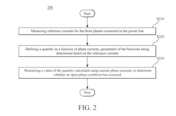
[0026] Figure 2 is a flowchart of a method 200 for detecting an open-
phase
condition of a power transformer on standby, according to an embodiment.
Method 200
starts by measuring reference currents for the three phases connected to the
power line
at S210, i.e., the three phases of the high side of the transformer as shown
in Figure 5
and discussed below, when the transformer is loaded and when it is known that
there is
no open circuit condition.
[0027] More specifically, and purely as an illustrative example of step
210,
Figures 3A, 3B and 3C represent a measurement of the three reference currents,
310,
320 and 330, and their sum 340, in a triad of representations similar to the
representations in Figures 1A, 1B and 1C, for the standby case where the power
transformer is connected but unloaded. In standby, the phase currents are much
lower
(hundreds of mA) than the loaded currents (over 40 A) in Figures 1A, 1B and
1C.
CA 02988618 2017-12-06
WO 2016/205479 PCT/US2016/037819
Additionally, as shown in Figure 3B and observed from the more complex time
evolution
in Figure 3A, the harmonics (at frequency multiples of 60 Hz) become more
significant.
Figure 3B reveals that the phase differences between the reference currents
depart
significantly from 120 . Finally, in standby, the sum of the phase currents
I_N (labeled
340) has a magnitude which is significant relative to the reference currents'
magnitudes.
Specifically, the reference currents in Figures 3A, 3B and 3C have the
following RMS
values and phase differences: I_A = 747.3 mA, I_B = 484.52 mA, I_C = 792.0 mA,
I_N
= 216.62 mA, I_A ¨ I_B = 93.9 , I_B ¨ I_C = 103.2 , and I_C ¨ I_A = 162.9 .
From
these measured reference current values, the "fingerprint" of this particular
(and purely
illustrative) transformer in standby without an open-phase condition can be
derived.
Note, for example, that without a load on the transformer secondary, the three
phases
exhibit: significant differences in amplitude, relative phase angles which
differ
significantly from 120 degrees, have relatively high harmonic content and
exhibit a
neutral current that is a good fraction of the phase magnetization currents.
[0028] For example, and returning now to method 200, at S220 at least one
quantity is defined as a function of phase currents. That is, parameters of
the functions
are determined based on the reference currents, examples of which are provided
below.
According to an embodiment at least one quantity is used to detect the open-
phase
condition. For example, an excitation aerial current, IE, an unexpected aerial
value, lu,
and/or the textbook zero sequence current, lo, may provide an alternative
manner of
11
CA 02988618 2017-12-06
WO 2016/205479 PCT/US2016/037819
carrying the information from the phase currents, IA, 1,8 and lc. The
excitation aerial
current may be a measurement of the similarity of phase currents to the
reference
currents. The zero sequence current is the sum of the reference currents.
According to
an embodiment, the unexpected aerial current is advantageously defined so that
its
value is zero for the reference currents.
[0029] According to a non-limiting embodiment, the excitation aerial
current, lE,
the unexpected aerial current, lu, and the zero current, lo, are calculated
as:
/ 1 1 1 \
N1(-1-2fl) N1(fl-1) N1(13+2) lA
IE =1 a- a- a- (1)
3
N2(2a+ 1) N2 (1-a) N2 (-2-a) lc
a- a- a- /
for the phase currents, IA, 1,8 and lc, with N1 and N2 being normalization
factors, a an
arbitrary complex number, and calculated as = ¨ 2a+17 (the symbol *
indicating
*
complex conjugate, and N1 = T_13 A/1 + 1a12 + la + 112, and N2 = 1fl12 + l
+ 112.
[0030] Here, a may be calculated so that the unexpected aerial current is
zero for
the reference currents. Thus a is calculated as:
a =
IAB-EIBR-21CR (2)
-2/ARd-/BR+icR
wherein IAR, IBR and IcR are the reference currents.
[0031] Formula (1) being written in vector form is easily converted into
algebraic
form, (e.g., 10=i/3(1,4+1,8+1c), etc.), and may be inverted to express the
phase currents as
12
CA 02988618 2017-12-06
WO 2016/205479 PCT/US2016/037819
functions of the excitation aerial current, IE, the unexpected aerial current,
lu, and the
zero current, /o:
(A) /1 1/N1 1/N2 \
= 1 ¨(a +1)/N1 ¨(f3 +1)1N2 lE. (3)
ic \1 /N2 /N2I)
u
[0032] Finally, at S220 of method 200, values of the one or more
quantities
calculated using current phase current values are monitored to determine
whether an
open-phase condition has occurred. For example, Figures 4A, 4B and 4C (the
same
triad of representations as Figures 1A, 1B and 1C or Figures 3A, 3B, and 3C)
illustrate
phase currents, 410, 420 and 430, and their sum, measured while phase C is
open. In
this case, the RMS values and phase differences between the phase currents are
as
follows: I_A = 1.4124 A, I_B = 985.6 mA, I_C = 81.74 mA, I_N = 2.1633 A, I_A ¨
I_B =
43.4 and I B¨I C and I C¨I A cannot be determined.
[0033] The RMS value(s) of the one or more quantities described above can
be
monitored, e.g., computed based on the measurements taken as reflected by
Figures
4A-4C, to determine if one of the values exceeds a pre-defined threshold for a
predetermined length of time. The threshold levels to be exceeded and the
length of
time required to declare an open phase condition depends on each transformer
and its
particular situation within the larger power system. For example, the open-
phase
condition may be identified when the ratio of the unexpected aerial current
and the
excitation aerial current (1u/lE) increases to exceed a predetermined
threshold.
13
CA 02988618 2017-12-06
WO 2016/205479 PCT/US2016/037819
Alternatively or additionally, the open-phase condition may be identified when
the ratio
of the zero current and the excitation aerial current (10/1E) increases to
exceed a
predetermined threshold (the predetermined thresholds are different, depending
on the
ratio with which they are compared). An exemplary threshold for IU/IE is 0.3
to 0.5, and
exemplary threshold for10/IE is 0.5 to 1.0, and an exemplary time that the
threshold(s)
need to be exceeded to trigger an alarm is 3-60 seconds.
[0034] In one embodiment, the phase currents' values may be considered in
addition to the ratio(s). Thus, the open-phase condition may also be
identified when
any of the phase currents becomes lower than a predetermined low threshold, or
higher
than a predetermined high threshold, and the first ratio or the second ratio
exceeds a
complementary first ratio threshold or a complementary second ratio threshold,
respectively. The "complementary" label used here indicates that these
thresholds may
be different from the thresholds used when the ratios are considered
individually.
[0035] The method may further include issuing an alarm signaling that the
open-
phase condition has been identified. As previously mentioned, the power
transformer is
in standby, ready to be connected to critical equipment if necessary. The
alarm would
prompt operators to repair the open phase before the need to connect critical
equipment
occurs.
[0036] Various tests have shown that in an open-phase condition, the
ratios lu/IE
and 10/1E may increase by over 30-50 `)/0 relative to their baseline or
reference values,
14
CA 02988618 2017-12-06
WO 2016/205479
PCT/US2016/037819
depending upon the type of transformer being monitored, e.g., wye or delta
high side,
core or shell form construction. However the setting of the thresholds also
depends
upon the desired balance for a particular implementation between security and
dependability. The higher that the thresholds are set, the more secure the
system is
against false trips, but the less dependable the system is for tripping in the
case of a
real open phase.
[0037] The
open phase detection methods described in this section have been
implemented in a controller (i.e., open-phase detection system) described
below and
schematically illustrated in Figure 5. Power transformer 510 has high-side
terminals
512, 513 and 514 connected to power line phases, while the low-side terminals
516,
517 and 518 are unloaded. Optical current transformers (OCTs) 522, 523 and 524
of
fiber construction (as described, for example, in Chapter 27, entitled,
"Optical Fiber
Current and Voltage Sensors for Electric Power Industry," of the Handbook of
Optical
Fiber Sensing Technology, pp. 569-618, published by Wiley and Sons in 2002)
are
disposed to measure the phase currents. OCTs have measurement advantages over
conventional iron core current transformers, which include a dynamic range
orders of
magnitude wider, no saturation, and much larger frequency response, including
direct
(continuous) current. Because of the wide dynamic range of the OCT, the same
sensor
can be used to detect both the magnetizing currents flowing into an unloaded
power
transformer as well as the currents flowing into it when it is loaded,
including fault
CA 02988618 2017-12-06
WO 2016/205479 PCT/US2016/037819
currents. Although the embodiment in Figure 5 uses OCTs, OCT use is not
compulsory, being a designer choice and not a limitation, and the embodiments
described herein can be implemented using, for example, non-optical current
sensing
techniques.
[0038] Current detection signals from the OCTs are processed by
electronics
block 530 and logic processing block 540. In a multi-stream digital signal
processing,
electronics block 530 filters and combines the signals to yield information
used by logic
processing block 540 to determine whether the open-phase condition has
occurred. As
previously mentioned, the "fingerprint" (i.e., reference values) of currents
is used to
frame the open-phase detection decision.
[0039] Electronics block 530 may be configured to filter the current
detection
signals received while the power transformer is on standby (i.e., the low side
is
unloaded). As described in WO 2015/073510 (the content of which is
incorporated
herein by reference), the standby current detection signals may be filtered
using a comb
filter. Further, electronics block 530 may be programmed to calculate the
parameters
based on reference currents. These parameters are then used to calculate one
or more
quantities which are a function of phase currents, with the functions using
these
parameters calculated based on the reference currents. For example, these
quantities
may include the excitation aerial current, IE, the unexpected aerial current,
lu, the zero
current, lo, the ratio lu/IE and/or the ratio /0//E.
16
CA 02988618 2017-12-06
WO 2016/205479 PCT/US2016/037819
[0040] Electronics block 530 then transmits these quantities to logic
processing
block 540, which is configured to compare these quantities with thresholds to
identify
that the open-phase condition has occurred based on the comparison result(s),
individually or in combinations. In one embodiment, electronics block 530 also
provides
the filtered phase currents values to logic processing block 540, enabling
comparison of
these currents with respective thresholds.
[0041] As previously mentioned, OCTs may also be used to detect the
higher
currents when the low side is loaded. In this case, electronics block 530 may
lightly
filter the signals using different filters than for the low currents when the
power
transformer is on standby. A prototype using an IEC 61850-9.2LE process bus
relay as
logic processing block 540 has recently been tested. A three-phase OCT
electronics
block was configured to feed 12 quantities to the relay via a 61850-9.2LE
optical
Ethernet connection. The 12 quantities included phase currents, and quantities
derived
based on the phase currents (i.e., functions of the phase currents).
[0042] Hardware able to detect a standby power transformer's open-phase
condition may be added to existing power plants. Figure 6 is a flowchart of a
method
600 for setting up hardware able to detect an open-phase condition of a power
transformer connected to three phases of a power line on a high-voltage side
and
unloaded on the low side, according to an embodiment. Method 600 includes
disposing
current sensing elements able to sense currents, e.g., as low as lmA, on the
three
17
CA 02988618 2017-12-06
WO 2016/205479 PCT/US2016/037819
phases at S610, and connecting the current sensing elements to a signal-
processing
apparatus at S620. Steps S610 and S620 set forth an equipment-mounting phase.
[0043] Method 600 further includes measuring reference currents for the
three
phases connected to the power line, using the current-sensing elements at S630
and
calculating, by the signal-processing apparatus, parameters of functions of
phase
currents, based on the reference currents at S640. Steps S630 and S640
constitute a
calibration phase.
[0044] Finally, in step S650 of method 600, values of the functions for
current
phase currents are monitored to determine whether the transformer has been
disconnected from one of the three phases.
[0045] The disclosed exemplary embodiments provide methods and
controllers
for detecting an open-phase condition in standby power transformers. It should
be
understood that this description is not intended to limit the invention. On
the contrary,
the exemplary embodiments are intended to cover alternatives, modifications
and
equivalents, which are included in the spirit and scope of the invention as
defined by the
appended claims. Further, in the detailed description of the exemplary
embodiments,
numerous specific details are set forth in order to provide a comprehensive
understanding of the claimed invention. However, one skilled in the art would
understand that various embodiments may be practiced without such specific
details.
18
CA 02988618 2017-12-06
WO 2016/205479 PCT/US2016/037819
[0046] Although the features and elements of the present exemplary
embodiments are described in the embodiments in particular combinations, each
feature or element can be used alone without the other features and elements
of the
embodiments or in various combinations with or without other features and
elements
disclosed herein.
[0047] This written description uses examples of the subject matter
disclosed to
enable any person skilled in the art to practice the same, including making
and using
any devices or systems and performing any incorporated methods. The patentable
scope of the subject matter is defined by the claims, and may include other
examples
that occur to those skilled in the art. Such other examples are intended to be
within the
scope of the claims.
19