Language selection

Search

Patent 2988834 Summary

Third-party information liability

Some of the information on this Web page has been provided by external sources. The Government of Canada is not responsible for the accuracy, reliability or currency of the information supplied by external sources. Users wishing to rely upon this information should consult directly with the source of the information. Content provided by external sources is not subject to official languages, privacy and accessibility requirements.

Claims and Abstract availability

Any discrepancies in the text and image of the Claims and Abstract are due to differing posting times. Text of the Claims and Abstract are posted:

  • At the time the application is open to public inspection;
  • At the time of issue of the patent (grant).
(12) Patent: (11) CA 2988834
(54) English Title: WIND TURBINE ROTOR BLADE WITH DEFLECTION UNITS
(54) French Title: PALE DE ROTOR D'EOLIENNE MUNIE DE MODULES DE DEFLEXION
Status: Granted
Bibliographic Data
(51) International Patent Classification (IPC):
  • F03D 80/40 (2016.01)
  • F03D 1/06 (2006.01)
(72) Inventors :
  • PAWIS, TORSTEN (Germany)
  • STRICKMANN, GOLO (Germany)
(73) Owners :
  • WOBBEN PROPERTIES GMBH (Germany)
(71) Applicants :
  • WOBBEN PROPERTIES GMBH (Germany)
(74) Agent: OYEN WIGGS GREEN & MUTALA LLP
(74) Associate agent:
(45) Issued: 2020-09-22
(86) PCT Filing Date: 2016-08-01
(87) Open to Public Inspection: 2017-02-09
Examination requested: 2017-12-08
Availability of licence: N/A
(25) Language of filing: English

Patent Cooperation Treaty (PCT): Yes
(86) PCT Filing Number: PCT/EP2016/068286
(87) International Publication Number: WO2017/021350
(85) National Entry: 2017-12-08

(30) Application Priority Data:
Application No. Country/Territory Date
10 2015 112 643.5 Germany 2015-07-31

Abstracts

English Abstract

The invention relates to a wind turbine rotor blade (200), comprising a rotor-blade root region (200a), a rotor-blade tip region (200b), a pressure side (200c), a suction side (200d), at least one fin (210, 211, 212), which extends along a longitudinal direction (L) of the rotor blade (200), and at least one deflecting unit (221, 222) between an end of the at least one fin (211, 212) and the rotor-blade tip region (200b). The at least one deflecting unit (221, 222) is designed to deflect an air flow traveling along the at least one fin (211, 212). Furthermore, at least one fin bead (300) is provided, which is arranged in the region of the at least one fin (210, 211, 212) in order to reduce turbulence of the air during the deflection.


French Abstract

L'invention concerne une pale d'éolienne (200) comprenant une zone racine (200a), une zone d'extrémité libre (200b), un côté pression (200c), une côté dépression (200d), au moins un segment (210, 211, 212) qui s'étend dans une direction longitudinale (L) de la pale (200) et au moins une unité déflectrice (221, 222) située entre une partie terminale dudit au moins un segment (211, 212) et la zone d'extrémité libre (200b) de la pale. Ladite au moins une unité déflectrice (221, 222) est conçue pour défléchir un flux de masse d'air incident s'écoulant sur ledit au moins un segment (211, 212). L'invention concerne également une bille de segment (300) qui est disposée dans la zone dudit au moins un segment (210, 211, 212) afin de réduire le tourbillonnement de la masse d'air lors de sa déflexion.

Claims

Note: Claims are shown in the official language in which they were submitted.


6

CLAIMS

1. A wind turbine rotor blade (200) comprising
a rotor blade root region (200a),
a rotor blade tip region (200b),
a pressure side (200c),
a suction side (200d),
a leading edge (201),
a trailing edge (202),
at least one fin (210, 211, 212) which extends along a longitudinal
direction (L) to the rotor blade (200),
at least one deflection unit (221, 222) between an end of the at least
one fin (211, 212) and the rotor blade tip region (200b),
wherein the at least one deflection unit (221, 222) is adapted to
deflect an air flow which is propagated along the at least one fin (211,
212), and
at least one fin drop-shaped portion (300) arranged in the region of
the at least one fin (210, 211, 212) to reduce turbulence of the air upon
deflection.
2. A wind turbine rotor blade according to claim 1 wherein
a first deflection unit (221) is arranged in the region of an end
(212a) of the at least one fin (212).
3. A wind turbine rotor blade according to claim 1 or claim 2 wherein
a second deflection unit (222) is provided between the first deflection
unit (221) and the rotor blade tip region (200b).
4. A wind turbine rotor blade according to one of claims 1 to 3
wherein
the first deflection unit (221) has a first and a second end (221a,
221b) and is of a round or elliptical configuration,

7
wherein the end (212a) of the at least one fin (212) projects beyond
the first and second end (221a, 221b) into the first deflection unit (221,
222).
5. A wind turbine rotor blade according to one of claims 1 to 4
wherein
the first deflection unit (221) is provided in the region of the end
(211a) of the first fin (211) and the second deflection unit (222) is provided

between the end (212a) of the second fin (212) and the rotor blade tip
region (200b).
6. A wind turbine rotor blade according to one of claims 1 to 5
wherein
the at least one fin drop-shaped portion (300) has a first end (310),
a second end (320) and a recess (330) at a side surface of the drop-shaped
portion (300),
wherein the first end (310) is of a pointed configuration and the
second end (320) is of a round configuration.
7. A wind turbine rotor blade according to claim 6 wherein
the recess (330) is provided laterally on the fin drop-shaped portion
(300), and
wherein the fin drop-shaped portion (300) is provided laterally on the
first fin (211) and/or the fin drop-shaped portion is provided laterally at
the
end (212a) of the second fin (212).
8. A wind turbine rotor blade according to one of claims 1 to 6
wherein
the at least one fin drop-shaped portion (300) is arranged at an end
of at least one fin (211, 212), wherein the end is towards the rotor blade
tip region (200b).

8
9. A method of heating a wind turbine rotor blade (200) which has a
rotor blade root region (200a), a rotor blade tip region (200b), a pressure
side (200c), a suction side (200d), a leading edge (201), a trailing edge
(202), at least a first and a second fin (211, 212) which extends along a
longitudinal direction of the rotor blade (200), and at least one fin drop-
shaped portion (300) arranged in the region of the at least one fin (210,
211, 212) to reduce turbulence in the air upon deflection, comprising the
steps:
introducing warmed air along the leading edge (201) and/or the
trailing edge (202), and
deflecting the warmed air which flows along the leading edge (201)
and/or the trailing edge (202).
10. The method according to claim 9 wherein deflecting the warmed
air comprises deflecting the warmed air into a region between the first and
second fins.

Description

Note: Descriptions are shown in the official language in which they were submitted.


Wind turbine rotor blade with deflection units
The present invention concerns a wind turbine rotor blade and a wind
turbine having a corresponding rotor blade.
As the rotor blades of a wind turbine are unprotectedly exposed to all
weather conditions icing of the rotor blades can occur at certain
temperatures. A rotor blade heating system can be used to prevent that.
In that case either heating can be provided externally on the rotor blade or
warmed air can be provided within the rotor blade.
On the German patent application from which priority is claimed the
German Patent and Trade Mark Office searched the following documents:
DE 200 14 238 Ul, DE 10 2010 051 297 Al, DE 10 2011 086 603 Al, DE
10 2005 034 131 Al and DE 195 28 862 Al.
An object of the present invention is to provide a wind turbine rotor
blade which permits improved heating of the rotor blade.
That object is attained by a wind turbine rotor blade as described
below.
Thus there is provided a wind turbine rotor blade comprising a rotor
blade root region, a rotor blade tip region, a pressure side, a suction side,
at least one fin which extends along a longitudinal direction of the rotor
blade and at least one deflection unit between an end of the at least one fin
and the rotor blade tip region. The at least one deflection unit is adapted
to deflect an air flow which is propagated along the at least one Fin.
According to an aspect of the present invention a first deflection unit
is provided in the region of an end of the first fin.
According to a further aspect of the present invention a second
deflection unit is provided between the first deflection unit and the rotor
blade tip.
According to a further aspect of the present invention the first
deflection unit has a first and a second end and is of a round or elliptical
CA 2988834 2019-05-17

2
configuration. An end of the first or second fin projects beyond the first
and second end into the deflection unit.
According to a further aspect of the present invention a drop-shaped
portion is provided at an end of the first or second fin.
According to a further aspect of the present invention a deflection
unit is provided in the region of an end of the first fin and a second
deflection unit is provided between the end of the second fin and the rotor
blade tip.
The invention concerns the notion of providing in the interior of a
wind turbine rotor blade in the region of the rotor blade tip a deflection
unit
in the region of an end of a fin of the rotor blade and/or a deflection unit
in
the region of the rotor blade tip. Provided in the rotor blade is at least one

fin which extends from the region of the rotor blade root in the direction of
the rotor blade tip without in that respect reaching the rotor blade tip.
Warmed air can flow along the fin in the direction of the rotor blade tip and
can be directed or deflected in the direction of the rotor blade root again by

the deflection means.
According to an aspect of the present invention the deflection unit is
in the form of a deflection plate. A main part of the air flow can be put into
a uniform configuration by a guide means which is round or portion-wise
ellipsoidal. The deflection plate can for example be made of foam.
Alternatively or additionally thereto fin drop-shaped portions can be
provided whereby an additional volume can be introduced to avoid steep
pressure gradients in the flow direction.
In addition or alternatively thereto a flow feed guide can be
provided. This can be effected for example by positioning a partition or the
fins in such a way that the intake flows (the warmed air) are combined in
the flow convergence guide in parallel and at the same speed.
Additionally or alternatively thereto it is possible to provide a
deflection element which has a change in cross-sectional area that is as
slight as possible.
Further embodiments of the invention are described below.
CA 2988834 2019-05-17

CA 02988834 2017-12-08
3
Advantages and embodiments by way of example of the invention
are described in greater detail hereinafter with reference to the drawing.
Figure 1 shows a diagrammatic view of a wind turbine according to
the invention,
Figure 2 shows a diagrammatic view of a portion of a rotor blade of
the wind turbine of Figure 1,
Figure 3 shows a portion of the rotor blade of Figure 2,
Figures 4A-4C show various views of a fin drop-shaped portion
according to the invention, and
Figure 5 shows a diagrammatic perspective view of a portion of a
wind turbine rotor blade according to the invention.
Figure 1 shows a diagrammatic view of a wind turbine according to
the invention. The wind turbine 100 has a tower 102 and a pod 104 on the
tower 102. Provided on the pod 104 is an aerodynamic rotor 106 having
three rotor blades 200 and a spinner 110. The aerodynamic rotor 106 is
caused to rotate by the wind in operation of the wind turbine and thus also
rotates a rotor or rotor member of a generator coupled directly or indirectly
to the aerodynamic rotor 106. The electric generator is arranged in the
pod 104 and generates electrical energy. The pitch angle of the rotor
blades 200 can be altered by pitch motors at the rotor blade roots of the
respective rotor blades 200.
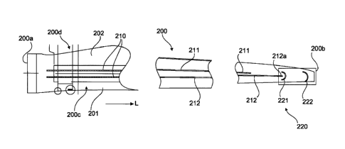
Figure 2 shows a diagrammatic view of a portion of a rotor blade of
the wind turbine of Figure 1. The rotor blade 200 has a rotor blade root
region 200a, a rotor blade tip region 200b, a leading edge 201, a trailing
edge 202, a pressure side 200c and a suction side 200d. At least one fin
210 extends within the rotor blade along a longitudinal direction of the
rotor blade 200. For example there can be two fins 211, 212 which can
initially be parallel and can be of a mutually converging configuration in the

region of the rotor blade tip 200b. In that respect the length of the first
fin
211 can be less than the length of the second fin 212. A first deflection
unit 221 can be provided in the region of an end 212a of the second fin
212. A second deflection unit 222 can be provided in the region of the tip
200b of the rotor blade.

CA 02988834 2017-12-08
4
Warmed air can be guided along the fins in the direction of the rotor
blade tip and then deflected.
Figure 3 shows a portion of the rotor blade of Figure 2. Figure 3
shows the rotor blade tip region 200b of the rotor blade 200. In particular
an end 212a of the fin 212 and the first and second deflection units 221,
222 are shown here.
According to the invention the first deflection unit 221, the second
deflection unit 222 or both deflection units 221, 222 can be provided.
Optionally the first deflection unit 221 can be of a round or elliptical
configuration and can have two ends 221a, 221b, wherein the end 212a of
the fin 212 projects beyond the first and second ends 221a, 221b into the
deflection unit 221. That can ensure that the air flow is effectively
deflected by the first deflection unit 221. In that respect it is possible to
achieve in particular a uniform configuration in respect of the main part of
the flow.
According to an aspect of the present invention fin drop-shaped
portions 300 can be provided at the fin end.
As can be seen from Figure 2 the spacing between the first and
second fins 211, 212 reduces in the direction of the rotor blade tip 200b.
Flow convergence can be achieved in that way. In particular the intake
flows can combine when the flows are brought together in parallel
relationship and at the same speed.
Figures 4A-4C show various views of a fin drop-shaped portion
according to the invention. Figure 4A is a plan view of a fin drop-shaped
portion 300, Figure 4B shows a perspective view of the fin drop-shaped
portion 300 and Figure 4C is a sectional view along line A-A in Figure 4B.
The fin drop-shaped portion 300 is provided or glued at a fin end as shown
in Figure 3. That fin drop-shaped portion is intended to improve deflection
of the warmed air in the region of the rotor blade nose and in the region of
the rotor blade rear box structure. The warmed air is deflected and flows
for example in the region between the fins back to the rotor blade root.
According to the invention the fin drop-shaped portion 300 can be
arranged laterally at a fin end.

CA 02988834 2017-12-08
The drop-shaped portion 300 has a first end 310, a second end 320
and optionally a recess 330 at the side surfaces of the drop-shaped portion.
The first end 310 is of a pointed configuration while the second end 320 is
of a round configuration.
5 Figure 5
shows a diagrammatic perspective view of a portion of a
wind turbine rotor blade according to the invention. The rotor blade 200
has a first and second fin 211, 212, a first and second deflection unit 221,
222 and a fin drop-shaped portion 300 at an end 211a of the first fin 211.
The first deflection unit 221 is provided in the region of the end 211a of the
first fin 211 while the second deflection unit 222 is provided in the region
of
the end 212a of the second fin 212. According to the invention the fin
drop-shaped portion 300 is provided laterally on the first fin 211. A fin
drop-shaped portion 300 can be also be provided at the end 212a of the
second fin 212.
The fin drop-shaped portion 300 can also be provided at other
locations along the fins (for example in the centre). The deflection unit can
be made for example from foam and forces the main part of the air flow
into a uniform configuration. The fin drop-shaped portion serves as an
additional volume for avoiding severe pressure gradients in the flow
direction. In addition the fin drop-shaped portions serve to round off the
corners.

Representative Drawing
A single figure which represents the drawing illustrating the invention.
Administrative Status

For a clearer understanding of the status of the application/patent presented on this page, the site Disclaimer , as well as the definitions for Patent , Administrative Status , Maintenance Fee  and Payment History  should be consulted.

Administrative Status

Title Date
Forecasted Issue Date 2020-09-22
(86) PCT Filing Date 2016-08-01
(87) PCT Publication Date 2017-02-09
(85) National Entry 2017-12-08
Examination Requested 2017-12-08
(45) Issued 2020-09-22

Abandonment History

There is no abandonment history.

Maintenance Fee

Last Payment of $210.51 was received on 2023-07-19


 Upcoming maintenance fee amounts

Description Date Amount
Next Payment if standard fee 2024-08-01 $277.00
Next Payment if small entity fee 2024-08-01 $100.00

Note : If the full payment has not been received on or before the date indicated, a further fee may be required which may be one of the following

  • the reinstatement fee;
  • the late payment fee; or
  • additional fee to reverse deemed expiry.

Patent fees are adjusted on the 1st of January every year. The amounts above are the current amounts if received by December 31 of the current year.
Please refer to the CIPO Patent Fees web page to see all current fee amounts.

Payment History

Fee Type Anniversary Year Due Date Amount Paid Paid Date
Request for Examination $800.00 2017-12-08
Application Fee $400.00 2017-12-08
Maintenance Fee - Application - New Act 2 2018-08-01 $100.00 2017-12-08
Registration of a document - section 124 $100.00 2018-03-13
Maintenance Fee - Application - New Act 3 2019-08-01 $100.00 2019-07-09
Final Fee 2020-09-14 $300.00 2020-07-21
Maintenance Fee - Application - New Act 4 2020-08-03 $100.00 2020-07-27
Maintenance Fee - Patent - New Act 5 2021-08-03 $204.00 2021-07-27
Maintenance Fee - Patent - New Act 6 2022-08-02 $203.59 2022-07-25
Maintenance Fee - Patent - New Act 7 2023-08-01 $210.51 2023-07-19
Owners on Record

Note: Records showing the ownership history in alphabetical order.

Current Owners on Record
WOBBEN PROPERTIES GMBH
Past Owners on Record
None
Past Owners that do not appear in the "Owners on Record" listing will appear in other documentation within the application.
Documents

To view selected files, please enter reCAPTCHA code :


To view images, click a link in the Document Description column. To download the documents, select one or more checkboxes in the first column and then click the "Download Selected in PDF format (Zip Archive)" or the "Download Selected as Single PDF" button.

List of published and non-published patent-specific documents on the CPD .

If you have any difficulty accessing content, you can call the Client Service Centre at 1-866-997-1936 or send them an e-mail at CIPO Client Service Centre.


Document
Description 
Date
(yyyy-mm-dd) 
Number of pages   Size of Image (KB) 
Amendment 2020-02-06 8 223
Claims 2020-02-06 3 80
Description 2019-05-17 5 210
Final Fee 2020-07-21 4 100
Representative Drawing 2020-08-26 1 6
Cover Page 2020-08-26 1 38
Abstract 2017-12-08 1 17
Claims 2017-12-08 3 75
Drawings 2017-12-08 4 56
Description 2017-12-08 5 205
Representative Drawing 2017-12-08 1 22
International Search Report 2017-12-08 4 115
Amendment - Abstract 2017-12-08 1 79
National Entry Request 2017-12-08 4 116
Cover Page 2018-02-23 1 43
Examiner Requisition 2018-11-26 5 254
Amendment 2019-05-17 14 460
Claims 2019-05-17 3 81
Examiner Requisition 2019-08-28 3 164