Note: Descriptions are shown in the official language in which they were submitted.
CA 02989090 2017-12-11
WO 2017/009189
PCT/EP2016/066186
- 1 -
"Machine of the piston type for dispensing coffee or other brewed
beverages"
The present invention relates in general to the sector of machines for
the preparation of beverages. More particularly, it relates to a machine
able to dispense brewed beverages, for example coffee, espresso
coffee, barley or other similar beverages. The machine is of the piston
type (also known as "lever" type).
Many machines for the preparation of beverages are known. In
particular, many machines for the preparation of espresso coffee from
coffee powder, pods, capsules or the like are known.
In particular coffee machines of the "lever" or "piston" type are
known. These machines typically comprise a system, the purpose of
which is to put under pressure the water required for producing the
coffee by making use of the energy stored in a spring preloaded by
means of a manual action.
Typically a piston machine comprises a cylinder and a piston with a
rod. A spring is housed inside the cylinder. The piston is raised against
the thrusting force of the spring actuated by an operating lever
connected to the piston rod by means of a raising arm. A filling hole
with, optionally, a check valve is provided in the cylinder wall. The seal
between piston and cylinder is generally ensured by sealing rings.
The pressure profile typically starts with a pressure of between about
9 bar and about 12 bar and ends with a pressure of between about 4
bar and 7 bar.
In a piston machine, the hot water from a boiler enters into the
cylinder through the filling hole. Entry of the hot water is possible only
when the piston reaches the high position.
As soon as the operator releases the operating lever, the spring
(which is no longer retained) pushes the piston downwards, this in turn
CA 02989090 2017-12-11
WO 2017/009189
PCT/EP2016/066186
- 2 -
pushing the water through a puck of coffee powder or the like.
In order to load the spring, it is required to operate the operating
lever which causes rotation of the reaction arm (rigidly connected to it)
which raises the rod to which the piston is connected. Finally, the
piston, being raised, compresses the spring. Therefore the (mechanical)
energy stored by the spring is provided by the operator.
The Applicant has noted that the piston machines of the
aforementioned type have a number of drawbacks.
In particular, the Applicant has noted that in the known machines the
water may be introduced only when the piston is in the upper position.
This limits greatly the use of the machine and the pressure profiles
which can be obtained.
Moreover, it is not possible, with the known machines to dispense a
quantity of beverage different from the standard amount. Therefore, for
example, it is not possible to dispense a ristretto coffee.
Moreover, the sealing rings of the piston during the piston stroke
pass over the water filling hole formed in the cylinder. The hole forms a
discontinuity in the surface of the cylinder which, however small, in the
long run causes wear of the sealing rings and creates leakage points.
Furthermore, the operating lever and the raising arm are rigidly
connected together and it is not possible to move one without moving
the other one.
GB 726 272 A discloses a coffee making machine.
The aim of the Applicant is to provide a machine for dispensing
brewed beverages, such as coffee, espresso coffee, barley or other
similar beverages, of the piston type which solves the aforementioned
problem of relative wear of the piston and cylinder and which offers
greater flexibility as regards the pressure profiles and the amounts
which may be dispensed.
According to the present invention, a coffee machine is provided,
CA 02989090 2017-12-11
6
=
WO 2017/009189
PCT/EP2016/066186
- 3 -
said coffee machine comprising: a cylinder, a piston which is
configured to perform a translation movement in said cylinder, a
rod having an end cooperating with said piston, an operating
lever (preferably rotatable), a spring, a member configured to
cooperate with said rod and to move said piston from a first
position to a second position in which said spring is at least
partially compressed, a boiler configured for heating water
supplied from a water main supply at a first pressure, an
opening for introducing water from the boiler into the cylinder
configured so as to enter the water above the piston, wherein
the piston comprises a duct which is closed when said piston is
in its lower position and is open when said piston is in the
second position for let flow the water below the piston and a
pressure regulator to adjust the pressure of the water from said
first pressure to a second pressure. In this manner the pressure
of water in the boiler can be changed and, finally, the pressure
reaching the coffee can be different or varied.
Preferably, the pressure regulator is configured to adjust the
pressure of the water inside the boiler.
According to embodiments, the pressure regulator is manually
operated. According to other embodiments, the pressure
regulator comprises an electric valve programmable to obtain a
preset dispensing pressure profile. The dispensing pressure
profile can be either a substantially constant pressure profile or
a pressure profile comprising one pressure increase and/or one
pressure decrease.
The inlet opening is preferably configured to fill water in a chamber
which is at least partially delimited at the bottom by the piston and
delimited laterally by walls of the cylinder.
Preferably, the rod and the piston are configured to move reciprocally
- 4 -
relative to one another.
In embodiments, the axis of the spring forms a non-zero angle with the
axis of the rod.
The machine may comprise a member for adjusting the compression of
the spring.
In embodiments, the machine also comprises a pressure gauge for
showing the value of the pressure of the dispensed water.
In embodiments, the machine also comprises a mechanism which
realizes the connection between said operating lever and said eccentric
member, wherein said mechanism is of the "hold-to-operate" type. By "hold-
to-operate type" in this description and claims it is meant that said
operating
lever and said member are connected together only by means of a voluntary
action which is maintained by an operator of the coffee machine who holds
the lever. When the operator releases the operating lever at any position of
the lever, the operating lever and the member becomes unconnected. This
avoids that, if for any reasons (voluntary or not) the operator leaves the
holding of the lever, this becomes unconnected from the member and the
lever will not suddenly spring upwardly. This will avoid any risk for the
operator or for any person in proximity of him/her.
The member may be an eccentric member.
Accordingly, in one aspect, the present invention resides in a coffee
machine comprising: a cylinder, a piston which is configured to perform a
translation movement in said cylinder, a rod having one end cooperating with
said piston, an operating lever, a spring, a member configured to cooperate
with said rod and to bring said piston from a first position to a second
position
in which said spring is at least partly compressed, a boiler configured for
supplying heated water to the cylinder, an opening for introducing the heated
water from said boiler into said cylinder configured so as to enter the heated
water above the piston, wherein the piston comprises a duct which is closed
when said piston is in the first position and is open when said piston is in
the second position to let the heated water to flow below the piston, wherein
said opening is configured so as to permit the heated water to enter the
cylinder above the piston both when said piston is in the first position and
Date recue / Date received 2022-02-10
- 43 -
when said piston is in the second position, and a mechanism which realizes
a connection between said operating lever and said member, wherein said
mechanism is a hold-to-operate type mechanism and comprises a trigger.
BRIEF DESCRIPTION OF THE DRAWINGS
The present invention will become clearer from the following
description, provided by way of a non-limiting example, to be read with
reference to the accompanying drawings, in which:
- Figure 1 is a schematic cross-sectional view of an embodiment of the
present invention with the piston in its lower position (and the operating
lever raised);
- Figure 2 is a view, similar to that of Figure 1, but in the condition where
the
piston is raised (and the operating lever is lowered);
- Figures 3a-3c are schematic illustrations of alternative embodiments
Date recue / Date received 2022-02-10
CA 02989090 2017-12-11
WO 2017/009189
PCT/EP2016/066186
- 5 -
of the mechanism which rigidly connects the operating lever to the
eccentric member;
- Figure 4 is a cross-sectional view of the piston in its configuration
where it does not allow the passage of water;
- Figure 5 is a cross-sectional view of the piston in its configuration
where it allows the passage of water;
- Figure 6 is a schematic view of an embodiment of the present
invention showing a possible arrangement of the pressure regulator
and the pressure gauge;
- Figures 7a.1 and 7a.2 show a first pressure profile which can be
obtained with the machine of the present invention;
- Figures 7b.1 and 7b.2 show a second pressure profile which can be
obtained with the machine of the present invention;
- Figures 7c.1 and 7c.2 show a third pressure profile which can be
obtained with the machine of the present invention;
- Fig. 7d is an example of manual adjustment for obtaining a
substantially constant pressure;
- Figures 8a, 8b, 8c and 8d show a further embodiment of the machine
according to the present invention with spring axially offset from the
cylinder;
- Figure 9 shows the path of the eccentric member;
- Figure 10 shows two lever force diagrams which are substantially
equivalent;
- Figure 11 shows the qualitative progression of the lever force as a
function of the angle of rotation of the eccentric member (or lever);
and
- Figure 12 shows a qualitative diagram of the profile of the eccentric
member.
The description below, solely for the sake of convenience, refers in
particular to an espresso coffee machine, but the present invention is
CA 02989090 2017-12-11
WO 2017/009189
PCT/EP2016/066186
- 6 -
not limited to such machines and is applicable to machines for
dispensing other beverages. Therefore, the term "coffee", for the
purposes of the present description and the claims which follow, must
be understood in the widest sense so as to include also barley or the
like.
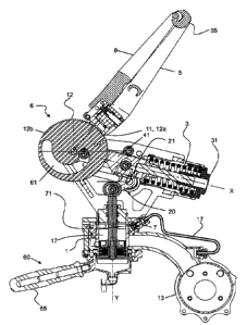
Figure 1 shows a schematic cross-section of a piston machine
according to an embodiment of the present invention in the
configuration where the piston is in the low position. Figure 2 shows,
again in a cross-sectional view, the same piston machine, but in its
configuration where the piston is in the high position. In the description
below (and in the claims) terms such as "upper", "high", "lower" and
"low" will be used. They are to be understood as being non-limiting, but
are used with reference to the figures.
The machine is identified overall by the reference number 100 and
comprises a cylinder 1, a piston 2, a spring 3, a rod 4, an operating
lever 5 and a boiler 13. In the various figures a filter holder 60 which
may be of any known type is also shown. Typically, it comprises a
hollow body 62 which is provided with a hole at the bottom and which
terminates in a (single or double) spout 63. The hollow body 62 is
configured to house a filter 64 filled with coffee powder or the like. The
filter holder is engaged on a ring of the machine (situated underneath
the dispensing chamber) in any known manner, for example with a
bayonet mechanism which is rotatably operated (by means of the
handle 65).
The operating lever 5 is rotatable about an axis 9 between a first
position (Figure 1) where the piston 2 is situated on the bottom of the
cylinder 1 and a second position (Figure 2) where the piston 2 is at its
maximum height inside the cylinder 1. The first position corresponds to
the configuration where the machine 100 is at rest or has just
completed dispensing of a coffee. The second position is instead the
CA 02989090 2017-12-11
=
WO 2017/009189
PCT/EP2016/066186
- 7 -
position of maximum compression of the spring 3, before dispensing of
the coffee at full pressure. As will become clear below, according to the
present invention, intermediate positions are also possible, including
that of Figure 1 and that of Figure 2.
The rod 4 of the piston 2 is connected, at a first end thereof (called
also "bottom end"), to the piston 2. The second opposite end (called
also "top end") of the rod 4 of the piston is connected to the operating
lever. Thus, a rotation of the operating lever from the position shown in
Figure 1 to that shown in Figure 2 causes raising of the piston 2 inside
the corresponding cylinder 1 and the corresponding compression of the
spring 3.
Preferably, the top end of the rod 4 cooperates with an eccentric
member 6 which can be associated with the lever 5. According to the
embodiment shown in the figures, the rod 4 cooperates with the
eccentric member 6 by means of a connecting piece 41 or other similar
extension element.
According to the embodiment shown in the Figures, the connecting
piece 41 terminates in a pin 42 configured to move in a guided manner
within a corresponding path 61 of the eccentric member 6. The path 61
is such that the centre of the pin 42 follows a trajectory different from a
circle arc trajectory. In other words, the distance between the rotation
axis 9 and the centre of the pin 42 varies during the movement guided
within the path 61. The effect of this guided movement is such that the
pin 42 moves towards the rotation axis 9 and thus raises the rod 4 (and
the piston 2). Obviously, in accordance with the diagram shown in the
Figures, the rod 4 performs a translational movement, while the
eccentric member 6 rotates.
According to an advantageous aspect of the present invention, the
operating lever 5 is not connected to the eccentric member 6 in a
permanent manner. Preferably, the operating lever 5 may be rigidly
CA 02989090 2017-12-11
WO 2017/009189
PCT/EP2016/066186
- 8 -
connected to the eccentric member 6 only when wished by the operator
and when the operator is applying a sufficient force on the operating
lever 5. If the operator releases the grip of the operating lever for any
reason, the operating lever and the eccentric member are disengaged,
thus preventing the operating lever, which is no longer retained, from
performing sudden movements which may cause damage to objects or
injury to persons.
According to one embodiment of the present invention, a trigger 8 is
provided and, when pressed by the operator, realizes the connection
between the operating lever 5 and the eccentric member 6. Preferably,
the trigger 8 is in the form of a lever 8, also called "secondary lever",
which is pivotably mounted on the main lever 5 in the vicinity of its
bottom end.
Figures 1 and 2 show an embodiment of the mechanism which
realizes the connection between the main lever 5 and the eccentric
member 6. This mechanism is preferably of the "hold-to-operate" type.
In other words, the main lever 5 and the eccentric member 6 may be
connected together only by means of a voluntary action which is
maintained by the operator.
According to the embodiment shown by way of example in the
figures, the main lever 5 and the secondary lever 8 (trigger) are
connected together by means of an elastic hinge 81. The hinge 81
comprises an L-shaped element rotatable about an axis 82 of a block
51 at the base of the main lever 5. A tooth 11 is present at the end of a
shank of the L. A trigger spring 10, or any other elastic member,
cooperates with the other shank of the L which is rigidly connected to
the bottom end of the secondary lever 8.
The secondary lever 8 is kept in a configuration removed from the
main lever 5 by means of a trigger spring 10, which is preferably weakly
loaded.
CA 02989090 2017-12-11
WO 2017/009189
PCT/EP2016/066186
- 9 -
When instead the main lever 5 and the secondary lever 8 are gripped
together by the hand the operator, overcoming the weak resistance of
the trigger spring 10, the tooth 11 engages in one of the notches 12 on
the periphery of the eccentric member 6. In this way, and for as long as
the operator keeps the lever 5 and the trigger 8 close together, the lever
5 is substantially rigidly connected to the eccentric member. Therefore,
in this configuration, the rotation of the operating lever 5 about the axis
9 by the operator causes rotation of the eccentric member 6.
The rotation of the eccentric member 6 results in raising of the rod 4
and the piston 2. Therefore, ultimately, the rotation of the eccentric
member 6 causes the compression of the spring 3.
If the operator does not grip the main lever 5 and the secondary lever
8 together, the tooth 11 does not engage with the periphery of the
eccentric member 6. Therefore, even of the lever is lowered (by
rotating it) this movement does not have any effect on the rod of the
piston and the spring 3 is not compressed.
If the operator grips together the main lever 5 and the secondary
lever 8 and then lowers them, but then, for any reason, accidentally
releases his/her grip, neither the main lever 5 nor the secondary lever 8
will return suddenly into the initial position because, when released by
the operator, the tooth 11 will cease to engage with the notch 12 of the
eccentric member. Therefore, the levers 5 and 8 will be free and not
restrained. Only the eccentric member 6 will return elastically owing to
the effect of decompression of the spring 3, but this will not cause any
injury to the operator.
Preferably, the periphery of the eccentric member 6 comprises one
or more notches 12 which can be engaged by the tooth 11. Preferably,
the periphery of the eccentric member 6 comprises a plurality of
notches 12, as shown in Figures 1 and 2. The plurality of notches 12
allows the compression of the spring 3 to be set. In fact, when the tooth
CA 02989090 2017-12-11
WO 2017/009189
PCT/EP2016/066186
-10-
11 engages the first notch 12a, the maximum compression of the spring
3 is obtained; when the tooth 11 engages the last notch 12b, the
minimum compression of the spring 3 is obtained; and finally, when the
tooth 11 engages the intermediate notch 12, an intermediate
compression of the spring 3 is obtained. It is also possible for the
operator to cause the tooth to engage with the first notch, but not rotate
the lever completely. A degree of compression of the spring 3 in turn
corresponds to a pressure for preparation of the coffee. In order to
engage an intermediate notch the lever 5 is first rotated through a few
degrees without operating the secondary lever and then the two levers
5 and 8 are gripped towards each other so as to cause engagement of
the tooth 11 inside the corresponding notch 12.
According to an embodiment of the present invention, an elastic
recall member is preferably provided for gently causing the lever 5 (and
the secondary lever 8 pivotably mounted on it) to return into the initial
position. Preferably the recall force is weak in order to prevent injury to
the operator.
The characteristic feature whereby the operating lever 5 and the
eccentric member are rigidly connected together by means of a
voluntary command which is maintained ("hold-to-operate" type) may
also be achieved with mechanisms which are different from that shown
in Figures 1 and 2.
From a conceptual point of view, the locking mechanism may be
divided into three zones: handle, transmission and connection.
"handle" (HDLE) refers to the zone where the operator applies
his/her force. "transmission" (TRANS) refers to the portion of the control
system which transfers the movement from the "handle" to the
"connection". "connection" (CONN) refers to that part of the mechanism
which comes into contact with the cam. Figures 3a, 3b and 3c show, in
CA 02989090 2017-12-11
WO 2017/009189
PCT/EP2016/066186
- 1 1 -
a very simplified form, three examples of variants of the locking
mechanism.
According to the variant shown in Figure 3a, the operating lever 5
could be substantially vertical and the handle could in the form of a
pushbutton 52.
According to the variant shown in Figure 3b, the operating lever 5
could be substantially vertical and the transmission could be realized by
means of a flexible member 53 such as a cable or a hydraulic pipe.
The connection between the operating lever 5 and the eccentric
member 6 may also be realized by means of friction. According to the
variant shown in Figure 3c, a gripper 54 configured to engage the sides
of the eccentric member 6 is used. The jaws 54' of the gripper 54 may
be operated by means of a cable transmission or in any other known
manner.
According to an advantageous embodiment of the present invention,
the hot water supplied from a boiler 13 or the like is introduced into the
cylinder 1 through an opening which is situated above the piston, both
when it is in the low configuration (Figure 4) and when it is in the high
configuration (Figure 5) where the spring 3 is at its maximum
compression.
Preferably, the hot water for preparation of the beverage passes from
the boiler 13 through a duct 13a which extends along the wall of the
cylinder 1 and enters into the cylinder 1 via a check valve 7 fixed to the
wall of the cylinder 1 in a specially provided housing. The path of the
water is indicated by means of lines with arrows in Figures 4 and 5. The
check valve ensures that the requirements stipulated by hygiene
standards are better satisfied. It prevents in fact traces of coffee from
rising up and entering the boiler.
Therefore, in contrast to piston machines of the known type, the
pressurized hot water is present inside the chamber 17 above the
CA 02989090 2017-12-11
WO 2017/009189
PCT/EP2016/066186
- 12 -
piston 2. The chamber 17 is delimited by a wall portion of the cylinder 1
and by the top side of the piston. This allows, during dispensing of the
coffee, generation of a thrust on the piston in addition to the thrust of
the spring 3. This has the advantage of allowing a weaker spring to be
used, for the same maximum dispensing pressure. In turn, this results
in a lower force applied to the operating lever 5. In fact, the action of the
operator has merely the function of compressing the spring 3.
The fact that the discontinuity inside the cylinder 1, due to the
presence of the check valve 7 and the corresponding opening 71, is not
situated along the stroke path of the piston 2 (but above it) ensures that
the piston gaskets or seals do not suffer any damage.
The fact that the pressurized hot water is present above the piston
provides a further possibility for adjusting the pressure of the coffee
dispensed. In fact, in some embodiments, it is possible to reduce (or
also increase or, in general terms, regulate) the pressure of the water
from the meter so as to supply the machine with a lower pressure. A
pressure regulator may be mounted upstream of the machine 100 or
may be incorporated inside the machine 100. This second solution is
considered to be more advantageous. Moreover, a (for example digital
or analog) pressure gauge may be provided for indicating the
dispensing pressure to the user of the machine. Advantageously, finally,
owing to the presence of the pressure gauge, the operator may
dispense the beverage in accordance with the desired pressure profile.
The pressure gauge may be connected by means of a hole formed in
the cylinder and in the assembly (top of the boiler). In this way it is
possible to read the pressure of the water immediately above the puck
of coffee.
According to an advantageous embodiment of the present invention,
the rod 4 and the piston 2 are not rigidly connected together, but a
CA 02989090 2017-12-11
WO 2017/009189
PCT/EP2016/066186
- 13 -
certain relative displacement is allowed. This displacement is
schematically illustrated in Figures 4 and 5.
Preferably, the rod 4 terminates in an enlarged part 41 and a disk 45.
The enlarged part 41 has a greater diameter than the rest of the rod 4.
This diameter substantially corresponds to the internal diameter of the
spring 3 so as to keep the spring 3 radially in the correct configuration in
alignment with the rod 4. The disk 45 retains longitudinally the spring 3
(which is retained above by the top of the cylinder 1). Therefore, the
bottom end of the spring 3 rests on the top side of the disk 45. A pin 43
extends underneath from the disk 45. According to one embodiment,
the pin 43 is screwed together with the enlarged part 41. The pin 43
terminates at the bottom with a head 44. The head may comprise an
incision for engagement by a tool (for example a flat-head or crosshead
screwdriver).
The piston 2 is substantially arranged slidably between the disk 45
and the head 44 of the pin 43. Sealing members 22 may also extend
above the disk 45 and/or below the head 44. According to one
embodiment, the piston 2 has a longitudinal central hole 23 inside which
the pin 43 is inserted.
The diameter of the piston hole is preferably greater than the
diameter of the pin 43.
Preferably, the height of the piston 2 is smaller than the length of the
pin 43.
Preferably, the piston 2 comprises one or more ducts 15 for the
passage of water from the top of the cylinder.
Preferably, a sealing member, for example a gasket 14, is provided
between the top side of the piston 2 and the bottom side of the disk 45.
The gasket 14 may be fixed to the top side of the piston 2 and/or to the
bottom side of the disk 45.
CA 02989090 2017-12-11
WO 2017/009189
PCT/EP2016/066186
- 14 -
In Figure 4, the rod 4, pushed by the spring 3, presses the piston 2
downwards. Preferably, the gasket 14 is compressed and therefore the
passage of the water through the ducts 15 formed in the piston is
prevented. Therefore, the pressurized hot water which is present inside
the cylinder above the piston cannot pass towards the filter with the
ground coffee (or other powder). The path of the water which cannot
pass through the piston is shown in schematic form in Figure 4 with two
arrows directed upwards.
Figure 5 shows instead the configuration where the rod 4 raises the
piston 2. The relative displacement of the rod 4 and the piston 2 allows
the duct 15 to be freed. In this way, the water which is supplied from
the boiler 13 (therefore substantially at the same temperature and the
same pressure as the water in the boiler) and which is always present
inside the cylinder 1 above the piston 2, passes through the duct 15 so
as to reach the puck of ground coffee (or other powder).
Therefore, very advantageously, introduction of the water can be
performed with the piston in any position (provided that it is not in the
completely lowered position shown in Figure 4). It is not required to
position the piston at the maximum height as in the known machines.
According to the present invention, it is possible to vary the pressure
profile without making any adjustments or changes to the machine
configuration. With reference to Figures 6, here below three different
categories of profiles are described, i.e. "Standard" (Figures 7a.1 and
7a.2), "Strong" (Figures 7b.1 and 7b.2) and "Light" (Figures 7c.1 and
7c.2). The first two types are also common to other machines, the
"Light" profile is an exclusive feature of the present invention.
It is possible to fully load the spring 3 by raising completely the piston
2, waiting for the water to fill entirely the dispensing chamber and then
allowing the piston 2 to descend back down completely pushed by the
CA 02989090 2017-12-11
WO 2017/009189
PCT/EP2016/066186
- 15 -
spring. The pressure profile which is obtained is the "Standard"
pressure profile shown in Figures 7a.1 and 7a.2.
It is also possible to perform dispensing by performing two or more
partial water filling operations by raising the piston 2 to its maximum
height. In this way a pressure profile is provided where the average
dispensing pressure is greater than the "Standard" pressure. The
pressure profile which is obtained is the "Strong" pressure profile shown
in Figures 7b.1 and 7b.2.
It is also possible to perform dispensing by performing two or more
partial water filling operations by raising the piston 2 to a height less
than the maximum height. In this way a pressure profile is provided
where the average dispensing pressure is less than the "Standard"
pressure. The pressure profile which is obtained is the "Light" pressure
profile shown in Figures 7c.1 and 7c.2.
Obviously, intermediate profiles are also possible where the piston
does not move up as far as the maximum height and does not move
down to the minimum height.
As already mentioned above, the dispensing pressure of the coffee is
due to the action of the spring 3 plus the thrust produced by the
pressure of the water in the boiler. Therefore, by adjusting the pressure
of the water inside the boiler by means of a suitable device which
reduces the pressure of the mains water to a set value, it is possible to
vary the pressure acting on the coffee.
Figure 6 is a schematic view of an embodiment of the present
invention showing a possible arrangement of pressure regulator 50 and
pressure gauge 52. In the embodiment of Figure 6, the pressure
regulator 50 is arranged upstream of the boiler 13. In such an
embodiment, pressure gauge 52 is arranged between the boiler 13 and
the pressure regulator 50 in order to measure the pressure value
CA 02989090 2017-12-11
WO 2017/009189
PCT/EP2016/066186
- 16 -
reaching the boiler 13. Figures 6 finally shows a discharge valve 54 for
overpressure discharging.
The pressure regulator could be adjusted by a certain amount,
manually during dispensing, for example by means of operation of a
knob or electrically during dispensing in order to obtain a preset profile.
According to other embodiments, the pressure regulator 50
comprises an electric valve programmable to obtain a preset dispensing
pressure profile. The dispensing pressure profile can be either a
substantially constant pressure profile or a pressure profile comprising
one pressure increase and/or one pressure decrease.
Fig. 7d shows an example of manual adjustment for obtaining a
substantially constant pressure of 10 bar. If the mains water is about 4
bar, the force of the spring 3 is adjusted so that on its own it exerts a
maximum pressure of about 9 bar and the regulator is adjusted
manually so as to generate a pressure which increases between 1 bar
and 4 bar. This effect could also be obtained by means of an electric
valve programmed to obtain a preset pressure profile.
Thanks to the possibility to vary pressure which reaches the coffee,
the preinfusion pressure can be adapted to the circumstances (desire of
the barista, blend of coffee, grinding size of the ground coffee).
In addition to the advantages mentioned above, the machine
according to the present invention has a high thermal stability. In fact,
the piston 2 is always in contact with the hot water of the boiler. During
filling and dispensing, the boiler water above and below the piston heats
the piston at both ends. When the machine is paused (piston in bottom
position) the water in the cylinder above the piston heats the piston from
above.
Therefore, also during long pauses between two dispensing
operations the piston is unable to cool. The temperatures of all the
CA 02989090 2017-12-11
WO 2017/009189
PCT/EP2016/066186
- 17 -
components in the assembly are more stable compared to the
conventional systems.
As mentioned above, the water enters into the dispensing chamber
via the ducts 15 formed in the piston 2 and not in the zone of the
cylinder 1 affected by the passing movement of the piston 2. Therefore
the sliding seals of the piston 2 do not encounter any discontinuity on
the surface of the cylinder and therefore wear thereof is reduced.
In conventional lever machines it is not possible to dispense a
measure of coffee which is different from the measure corresponding to
the maximum volume of the water filled in the cylinder. On the other
hand, with the machine according to the invention, a different measure,
for example a half-measure, may be dispensed. The progression of the
pressure as a function of the measure of coffee which can be dispensed
is substantially linear. That is, by raising completely the piston (fully
compressing the spring), the machine generates a maximum pressure
and may dispense a normal measure of coffee (for example about 50
ml of coffee). In order to obtain a half-measure (about 25 ml of coffee) it
is sufficient to raise the piston halfway along its stroke.
Figures 8a, 8b, 8c and 8d show a further embodiment of the machine
100 according to the present invention. The machine according to
Figures 8 is entirely similar to that shown in the preceding figures and,
for the sake of convenience, the same parts (or functionally equivalent
parts) have been indicated by the same reference numbers. So as not
overcomplicate needlessly the present description, the detailed
description provided for the first embodiment will not be repeated, but
the main differences will be highlighted.
As shown in Figures 8a, 8b and 8d, differently from the first
embodiment, the spring 3 is not in axial alignment with the rod 4.
During rotation of the eccentric member 6, with the aim of introducing
water in the cylinder 1, the eccentric member compresses the spring 3
CA 02989090 2017-12-11
WO 2017/009189
PCT/EP2016/066186
- 18 -
acting on a connecting piece 41 in a manner not dissimilar to that which
occurs in the case described above. However, so that this movement
also occurs during raising of the piston 2, a new element called a rocker
arm and indicated by the reference number 20 has been provided.
The rocker arm 20 is free to rotate about the axis 21 and is
connected to the connecting piece 41 at one of its ends and to the rod 4
at the other end.
During the rotation of the eccentric member 6, in addition to obtaining
the retraction movement of the connecting piece 41 which compresses
the spring 3, rotation of rocker arm 20 also occurs, this raising the rod 4
of the piston and consequently the piston 2.
Once the trigger 8 has been released at the end of the filling step, the
spring 3 is not restrained at all and is therefore free to expand,
displacing the connecting piece 41 which rotates the eccentric member
6 and rotates the rocker arm 20. The rotation of the rocker arm 20
lowers the rod 4 which lowers the piston 2.
The entry point for the water inside the cylinder 1 is visible in Figure
8c. The water heated in the boiler is preferably brought into contact with
the outer walls of the cylinder 1. Preferably, the water is introduced into
the cylinder via a pipe connected to a check valve. In this second
embodiment as well, the entry point for the water is in a position higher
than the piston, also when the latter is in the high position. This has all
the advantages mentioned above in connection with the first
embodiment.
According to the embodiment shown in Figures 8, the operating lever
5 has an ergonomic form with a horizontal handle. The horizontal
handle has the advantage that no change of grip is required during the
operating movement and therefore the risk that the operator will lose
his/her grip is kept to a minimum.
CA 02989090 2017-12-11
WO 2017/009189
PCT/EP2016/066186
- 19 -
Owing to the position of the spring 3 of the machine according to the
third embodiment, any replacement of the said spring may be
performed more easily. Moreover, the machine is less bulky, especially
the height is less and it is therefore easier to lower the operating lever
5.
Figure 8d shows a body 31 which acts as a housing for the spring 3.
Preferably, the housing 31 of the spring is threaded. Advantageously,
by screwing or unscrewing it, it is possible to vary the preload of the
spring 3. A greater preload produces an increase in the response of the
spring, a smaller preload produces a reduction in the response of the
spring. Consequently, it is possible to vary the pressure profile.
Figure 9 shows the travel path 61 of the eccentric member 6. This
travel path is configured so that the operator must exert a near constant
force during rotation of the operating lever 5.
As is known, the systems for loading a helical spring are devices
which convert the rotational movement of the operating lever into a
rectilinear movement which compresses the helical spring. The helical
spring requires a force so that it is compressed in a manner increasing
linearly with the compression. By way of example, the compression of a
helical spring of 0.1 m from a value of 100 N to a value of 300 N
requires about 20 J of energy. The way of reducing the maximum force
applied to the lever 5 is that of applying a constant force. For example,
with a displacement of 0.1 m, a constant force of 200 N supplies the
spring with an energy of 20 J. Therefore, the left-hand diagram in
Figure 10 is substantially energetically equivalent to the right-hand
diagram in the same Figure 10.
Advantageously, the machine according to the present invention is
configured to require an actuating force which is as constant as
possible.
CA 02989090 2017-12-11
WO 2017/009189
PCT/EP2016/066186
- 20 -
The travel path 61 of the eccentric member 6 has a profile designed
for this purpose. Figure 11 shows the qualitative progression of the
lever force as a function of the angle of rotation of the eccentric member
(or lever) according to the present invention.
The maximum force is only about twice greater than the minimum
force. In the known machines the maximum value is more than ten
times greater than the minimum value. Typically, the known lever type
machines have a maximum value more than 10 times greater than the
minimum value.
The cam profile refers to the mathematical function which associates
compression of the spring with rotation of the said cam. This function is
an increasing monotonic function.
In the description below the parameter relating to rotation has been
non-dimensionalized with a variable x comprised between 0 and 10.
"x=0" indicates the position of the cam corresponding to the piston in
the low position and minimum compression of the spring, while "x=10"
indicates the position relating to the piston in the high position and
maximum compression of the spring.
Preferably, the profile of the cam is represented by a curve lying
between the bottom and top lines of equations, i.e.:
bottom = 3-x+k with: 05.x510
and kER
(set of real numbers)
top = 3.x+k+10 with: 0sx510
and keR
(set of real numbers)
Even more preferably, the profile of the cam is represented by a
curve lying between the two bottom and top curves of equations, i.e.:
bottom = -0.013.x^3+0.1902+3-x+k with: 05xs10
and kER
(set of real numbers)
top = -0.013 03+0.1 =x^2+3=x+k+10 with: 0x_10 and
kER
(set of real numbers)
CA 02989090 2017-12-11
=
WO 2017/009189
PCT/EP2016/066186
-21 -
Figure 12 shows a graph of the non-dimensional parameter as a
function of the compression of the spring for k=16.