Note: Descriptions are shown in the official language in which they were submitted.
SUITCASE MOLDING PROCESS WITH OVERLAY
[01] [BLANK]
FIELD OF THE INVENTION
[02] The disclosed invention relates to a suitcase molding process for
making hard
shell luggage with textured surfaces or three-dimensional designs on surfaces
of the hard shells.
BACKGROUND
[03] Luggage may typically be divided into two categories ¨ soft luggage,
and hard
shell luggage. Soft luggage is typically wrapped in a soft material, such as
cloth, canvas, leather,
fabric, and/or vinyl. Soft luggage is typically constructed by forming an
internal frame from
metal and plastic materials which may be fastened together to define an
interior compaitment for
storing items. Padding may then be applied to the exterior and interior of the
plastic and metal
frame, before a soft, cloth material is applied to the exterior and interior
of the luggage by
stitching and/or adhering it to the luggage frame and cushioning. Soft luggage
is an attractive
choice for luggage designers because it allows the designer to create more
intricate details and
aesthetic features in the soft, cloth material, which is easily cut, stitched,
and arranged to create
visually appealing luggage designs. However, soft luggage is typically less
durable than hard
shell luggage and is subject to tearing, ripping, and staining during the
normal life of the
luggage.
[04] Hard shell luggage on the other hand is formed of a hard plastic
material such as
polyvinyl chloride (PVC), polyethylene (PE), polypropylene (PP), carbon fiber,
or Tegris0.
Hard shell luggage has the advantage of resisting deformation by external
forces, which affords
greater protection to the contents against damage as well as preserving the
overall shape and
appearance of the luggage. However, hard shell luggage can be heavier than
soft luggage, and
designers tend to have fewer options for altering the aesthetic appearance of
hard shell luggage,
given the typical methods of manufacturing hard shell luggage.
[05] Hard shell luggage may also require a more complex manufacturing
process, such
as injection molding or vacuum forming. These processes include the use of
expensive and
Date Recue/Date Received 2021-07-20
complex molding equipment, multiple heating and cooling steps, trimming steps,
and cleaning
steps to produce the luggage body. Once the front and rear hard shell
components of the luggage
are formed they are typically adhered to a metal frame that is placed on the
center-facing edge of
the hard shells. Locks, hinges, and other hardware is then connected to this
metal frame. Liners
and other internal components may also then be installed. This complex
manufacturing process
can be expensive and time consuming as compared to soft bags.
[06] Limited options are presently available to designers for improving the
overall
aesthetic appearance of hard shell luggage. For example, luggage designers may
seek to improve
the appearance of hard shell luggage by painting patterns on the surface of
the hard luggage
shell. However, this method requires additional labor and time for
individually painting each
luggage shell. Furthermore, painting may only provide a two-dimensional design
and does not
provide for a textured or three-dimensional aesthetic feature. Others have
sought to wrap hard
shells in additional, stylized materials such as cloth or canvas. Again,
however, this method
requires additional materials and parts for attaching the cloth to the hard
shells. Additional work
is also required to secure the cloth or canvas to the hard shell. As with
painting, this technique
also only provides for two-dimensional design features. Finally, some
designers have sought to
form patterns within the hard shells themselves, by creating a unique,
patterned mold for each
hard shell design. However, this method requires significant startup costs
associated with
fabricating individualized molds for each hard shell design. These increased
startup costs force
designers to adopt a smaller variety of hard shell luggage designs for longer
periods than they
may otherwise desire, and prevents designers from easily altering the
appearance of the hard
luggage shell.
[07] Items of luggage that attempt to combine certain features of hard and
soft bags are
described in U.S. Patent No. 6,936,127 to Fenton et al. and U.S. Patent No.
6,604,617 to Davis et
al. U.S. Patent No. 8,752,683 to Scicluna also teaches a relatively simple and
inexpensive
manufacturing technique for forming hard shell luggage. Nevertheless, there
remains a need for
a method of forming hard shells for luggage that allows luggage designers to
create new, three-
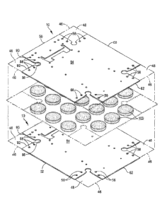
dimensional and/or textured designs for hard shell luggage and rapidly and
inexpensively
manufacture hard shell luggage using a multitude of designs and patterns.
2
Date Recue/Date Received 2021-07-20
SUMMARY OF THE INVENTION
[08] In one exemplary embodiment, a method for producing an article of
luggage may
be provided, including the steps of preparing a first layer of hard shell
material having a width
and a length, preparing a second layer of hard shell material having a width
and a length that is
substantially similar to the width and the length of the first layer of hard
shell material, disposing
one or more ornamental substrate between at least the first layer of hard
shell material and at
least the second layer of hard shell material; and forming the first layer of
hard shell material, the
second layer of hard shell material, and the one or more ornamental substrate
into a hard luggage
shell by heating the first layer of hard shell material, the second layer of
hard shell material, and
the one or more ornamental substrate together. In some examples, the
ornamental substrate is
disposed between a plurality of layers of hard shell material having
substantially similar widths
and lengths.
[09] In other examples the method may further include preparing a third
layer of hard
shell material having a width and a length that is substantially similar to
the width and the length
of the first layer of hard shell material, cutting openings into the third
layer of the hard shell
material wherein the holes substantially match the size, shape, and
arrangement of the
ornamental substrate. The step of forming the hard luggage shell may further
comprise placing
the third layer of hard shell material on top of the second layer of hard
shell material, such that
the holes in the third layer of hard shell material substantially align with
the ornamental
substrate, and pressing and/or heating the first layer of hard shell material,
the second layer of
hard shell material, and the ornamental substrate, and the third layer of hard
shell material
together.
[10] In some implementations, the ornamental substrate is formed from
plastic, metal,
wood, cardboard, styrofoam, and/or foam. In other examples, the hard shell
material comprises
polyvinyl chloride (PVC), polyethylene (PE), polypropylene (PP), carbon fiber,
and/or Tegris0.
[11] In some examples, methods may also include removing a portion of the
first,
second, and third layers of hard shell material proximate the corner to define
a notch, folding
first and second edges of the first, second, and third layers of hard shell
material to form first and
second sides, the first and second sides defining second and third faces of
the piece of luggage,
folding third and fourth edges of the first, second, and third layers of hard
shell material to form
third and fourth sides, the third and fourth sides defining fourth and fifth
faces of the piece of
3
Date Recue/Date Received 2021-07-20
luggage; and securing a rigid corner piece to the first and second sides
proximate the notch. In
some examples, at least one ornamental substrate is disposed within at least
one of the first,
second, third, and/or fourth sides of the first, second, and third layers of
hard shell material.
[12] Other examples of the present disclosure include a luggage article
comprising a
front hard shell section and a rear hard shell section, each of the front hard
shell section and the
rear hard shell section including, a first layer of hard shell material having
a width and a length, a
second layer of hard shell material having a width and a length that is
substantially similar to the
width and the length of the first layer of hard shell material, one or more
ornamental substrate
disposed between at least the first layer of hard shell material and at least
the second layer of
hard shell material, and wherein at least the first layer of hard shell
material, the second layer of
hard shell material, and the one or more ornamental substrate comprise a hard
shell section; and
wherein the first layer of hard shell material, the second layer of hard shell
material, and the one
or more ornamental substrate are formed into the hard shell section by heating
at least the first
layer of hard shell material, the second layer of hard shell material, and the
one or more
ornamental substrate together. In some examples, the ornamental substrate is
disposed between
a plurality of layers of hard shell material having substantially similar
widths and lengths.
[13] In some examples, the luggage article may also include a third layer
of hard shell
material having a width and a length that is substantially similar to the
width and the length of
the first layer of hard shell material, the third layer of the hard shell
material having holes that
substantially match the size, shape, and arrangement of the ornamental
substrate, and the third
layer of hard shell material is disposed on top of the second layer of hard
shell material, such that
the holes in the third layer of hard shell material align with the ornamental
substrate whereby at
least a portion of the ornamental substrate protrudes through the holes.
[14] In some examples, the ornamental substrate is formed from plastic,
metal, wood,
cardboard, and/or foam. In other examples, the hard shell material comprises
polyvinyl chloride
(PVC), polyethylene (PE), polypropylene (PP), carbon fiber, and/or Tegris0. In
some
implementations, the first, second, and third layers of hard shell material
have at least one corner
wherein a portion of the hard shell material been removed forming at least one
notch proximate
4
Date Recue/Date Received 2021-07-20
CA 02989164 2017-12-11
WO 2017/004530 PCT/US2016/040714
the at least one corner, wherein first and second edges of the at least one
section adjacent the
notch are folded inward relative an inner surface of the at least one section
forming first and
second sides, the first and second sides defining second and third faces of
the article of luggage,
and at least one rigid corner piece secured to the first and second sides
proximate the at least one
notch, and the third and fourth edges of the first, second, and third layers
of hard shell material
adjacent a second notch are folded inward relative the inner surface forming
third and fourth
sides, the third and fourth sides defining fourth and fifth faces of the
luggage article.
[15]
BRIEF DESCRIPTION OF THE DRAWINGS
[16] Various aspects of at least one embodiment are discussed below with
reference to the
accompanying figures. The figures are provided for the purposes of
illustration and explanation
and are not intended as a definition of the limits of the invention. In the
figures:
[17] FIG. 1 is a three-quarter back perspective view of a first exemplary
embodiment of a
piece of luggage according to the disclosed subject matter;
[18] FIG. 2 is a front view of the piece of luggage of FIG. 1;
[19] FIG. 3 is a back view of the piece of luggage of FIG. 1;
[20] FIG. 4 is a right side view of the piece of luggage of FIG. 1, the left
side view being
substantially a mirror image of the right side view;
121] FIG. 5 is a top view of the piece of luggage of FIG. 1;
[22] FIG. 6 is a cut-away view of an interior portion of the piece of luggage
showing an inner
fastening piece secured to a rigid corner piece according to an exemplary
embodiment of the
disclosed subject matter;
[23] FIG. 7 is a plan view of a first section of the stiff shell material
according to the first
exemplary embodiment of the disclosed subject matter;
[24] FIG. 8 is a plan view of a second section of the stiff shell material
according to the first
exemplary embodiment of disclosed subject matter;
[25] FIG. 9 is a plan view of a first section of the stiff shell material
according to a second
exemplary embodiment of the disclosed subject matter;
[26] FIG. 10 is a plan view of a second section of the stiff shell material
according to the
second exemplary embodiment of the disclosed subject matter;
CA 02989164 2017-12-11
WO 2017/004530 PCT[US2016/040714
[27] FIG. 11 is a three-quarter back perspective view of a second exemplary
embodiment of a
piece of luggage according to the disclosed subject matter;
[28] FIG. 12 is a cross section of a section of stiff shell material according
to an exemplary
embodiment of the disclosed subject matter;
[29] FIG. 13 is an exploded perspective view of an ornamental substrate in the
form of a grid
between two layers of stiff shell material according to an exemplary
embodiment of the disclosed
subject matter;
[30] FIG. 14 is an exploded perspective view of an ornamental substrate in the
form of parallel
lines between two layers of stiff shell material according to an exemplary
embodiment of the
disclosed subject matter;
[31] FIG. 15 is an exploded perspective view of an ornamental substrate in the
form of dots
between two layers of stiff shell material according to an exemplary
embodiment of the disclosed
subject matter.
[32] FIG. 16 is an exploded perspective view of an ornamental substrate in the
form of a
textured surface between two layers of stiff shell material according to an
exemplary
embodiment of the disclosed subject matter;
[33] FIG. 17 is an exploded perspective view of an ornamental substrate in the
form of a logo
between two layers of stiff shell material according to an exemplary
embodiment of the disclosed
subject matter;
[34] FIG. 18 is an exploded perspective view of an ornamental substrate in the
form of a
monogram between two layers of stiff shell material according to an exemplary
embodiment of
the disclosed subject matter;
135] FIG. 19 is an exploded perspective view of an ornamental substrate
between a first and
second layer of stiff shell material and a third layer of stiff shell material
with holes
corresponding to the ornamental substrate according to an exemplary embodiment
of the
disclosed subject matter; and
[36] FIG. 20 is an exploded perspective view of an ornamental substrate in the
form of both a
logo and dots between a first and second layer of stiff shell material and a
third layer of stiff shell
material with holes corresponding to the ornamental substrate according to an
exemplary
embodiment of the disclosed subject matter.
6
CA 02989164 2017-12-11
WO 2017/004530 PCT/US2016/040714
LIST OF REFERENCE NUMERALS UTILIZED IN THE DRAWINGS
[37] With regard to reference numerals used, the following numbering is used
throughout the
description and drawings. Where technical features in the figures or detailed
description are
followed by these reference numerals, the reference numerals have been
included for the sole
purpose of increasing the intelligibility of the figures or detailed
description. Accordingly,
neither the reference numerals nor their absence are intended to have any
limiting effect on the
scope of any claim elements. In the figures, each identical or nearly
identical component that is
illustrated in various figures is represented by a like numeral. For purposes
of clarity, not every
component may be labeled in every figure.
[38] Reference numeral 2 refers to a piece of luggage.
[39] Reference numeral 10 refers to a rear shell section of luggage.
[40] Reference numeral 12 refers to a rear face of luggage.
[41] Reference numeral 14 refers to a side panel of luggage.
[42] Reference numeral 16 refers to a side panel of luggage.
[43] Reference numeral 18 refers to a side panel of luggage.
[44] Reference numeral 20 refers to a side panel of luggage.
[45] Reference numeral 22 refers to a top side of luggage.
[46] Reference numeral 24 refers to a bottom side of luggage.
147] Reference numeral 26 refers to a left side of luggage.
[48] Reference numeral 28 refers to a right side of luggage.
[49] Reference numeral 30 refers to a front shell section of luggage.
[50] Reference numeral 32 refers to a front face of luggage.
151] Reference numeral 34 refers to a side panel of luggage.
152] Reference numeral 36 refers to a side panel of luggage.
[53] Reference numeral 38 refers to a side panel of luggage.
[54] Reference numeral 40 refers to a side panel of luggage.
[55] Reference numeral 42 refers to luggage wheels.
[56] Reference numeral 44 refers to a handle.
[57] Reference numeral 45 refers to an extendable handle.
[58] Reference numeral 46 refers to a corner of a layer of stiff shell
material.
[59] Reference numeral 48 refers to a notch in a layer of stiff shell
material.
7
CA 02989164 2017-12-11
WO 2017/004530 PCT[US2016/040714
[60] Reference numeral 50 refers to an edge of a layer of stiff shell
material.
[61] Reference numeral 52 refers to an edge of a layer of stiff shell
material.
[62] Reference numeral 54 refers to an inner surface of a layer of stiff shell
material.
163] Reference numeral 56 refers to a rigid corner piece for luggage.
[64] Reference numeral 58 refers to holes.
[65] Reference numeral 60 refers to an edge of a layer of stiff shell
material.
[66] Reference numeral 62 refers to an edge of a layer of stiff shell
material.
[67] Reference numeral 66 refers to an edge of a layer of stiff shell
material.
168] Reference numeral 68 refers to an edge of a layer of stiff shell
material.
[69] Reference numeral 70 refers to an edge of a layer of stiff shell
material.
[70] Reference numeral 72 refers to an edge of a layer of stiff shell
material.
[71] Reference numeral 74 refers to an inner surface of a layer of stiff shell
material.
[72] Reference numeral 76 refers to a gusset.
[73] Reference numeral 78 refers to a zipper.
[74] Reference numeral 84 refers to an outer surface.
[75] Reference numeral 86 refers to support structures.
[76] Reference numeral 88 refers to a notch in a layer of stiff shell material
having a semi-
circular shape.
177] Reference numeral 90 refers to an edge of a layer of stiff shell
material.
[78] Reference numeral 92 refers to an edge of a layer of stiff shell
material.
[79] Reference numeral 94 refers to a surface coating.
[80] Reference numeral 96 refers to layers of stiff shell material.
[81] Reference numeral 98 refers to an inner fastening piece.
[82] Reference numeral 101 refers to surface ornamentation.
[83] Reference numeral 103 refers to an ornamental substrate.
[84] Reference numeral 105 refers to a first layer of stiff shell material.
[85] Reference numeral 107 refers to a second layer stiff shell material.
[86] Reference numeral 109 refers to a third layer of stiff shell material.
[87] Reference numeral 111 refers to a plurality of openings in a layer of
stiff shell material.
DETAILED DESCRIPTION
8
CA 02989164 2017-12-11
WO 2017/004530 PCT[US2016/040714
[88] Reference will now be made in detail to representative embodiments
illustrated in the
accompanying drawings. It should be understood that the following descriptions
are not
intended to limit the embodiments to one preferred embodiment. To the
contrary, it is intended
to cover alternatives, modifications, and equivalents as may be included
within the spirit and
scope of the described embodiments as defined by the appended claims.
[89] As disclosed herein, the devices and methods presented can be used for
lightweight, high-
strength luggage with a multitude of patterns and designs appearing on the
exterior of the body
of the luggage.
[90] For the purpose of explanation and illustration, and not limitation, an
example of a
suitcase is shown in FIGS. 1-6. As illustrated, the suitcase shown in FIGS. 1-
6 can be of any
suitable specific construction in terms of materials, manner of assembly, and
configurations of
the parts. The suitcase 2, as shown in FIGS. 1-5, includes a rear section 10
and/or front section
30 made of a stiff shell material, such as a woven polypropylene (PP)
thermoplastic composite
having characteristics described herein below, such as polyvinyl chloride
(PVC), polyethylene
(PE), polypropylene (PP), carbon fiber, or Tegris polypropylene moldable
fabric manufactured
by Milliken (available at http://www.milliken.com/MFT); however, a person
having ordinary
skill in the art will recognize that any suitable fabric, plastic, metal, or
any other suitable material
having a high stiffness-to-weight ratio and high impact resistance can be
used.
[91] The rear section 10 can have a substantially rigid main panel defining a
rear face 12 of
the luggage 2, and side panels 14, 16, 18, 20, which can partially define top
22, bottom 24, left
side 26, and right side 28 faces of the luggage 2. The luggage 2 can also have
a front shell
section 30has a substantially rigid main panel, defining a front face 32 of
the luggage, and side
panels 34. 36, 38, 40, which can further define the top 22, bottom, 24, left
side 26, and right side
28 faces of the luggage 2.
[92] In some embodiments, front shell section 30, rear shell section 10,
top face 22, bottom
face 24, left side face 26, and right side face 28 of luggage 2 may also
include surface
ornamentation 101. Surface ornamentation 101 may comprise any three-
dimensional, raised,
and/or textured pattern or design suitable for placement on a luggage item. As
shown in FIGS.
1-6, for example and without limitation, surface ornamentation may take the
form of a chain-link
or grid pattern in some embodiments. However, as discussed in greater detail
below, surface
ornamentation 101 may take any form selected by the designer, including any
shapes, lines,
9
CA 02989164 2017-12-11
WO 2017/004530 PCT/US2016/040714
patterns, or raised surfaces. In some embodiments, surface ornamentation 101
may be located on
one or more of front shell section 30, rear shell section 10, top face 22,
bottom face 24, left side
face 26, and right side face 28. In other embodiments, surface ornamentation
101 may have a
substantially uniform pattern and/or appearance on each of front shell section
30, rear shell
section 10, top face 22, bottom face 24, left side face 26, and right side
face 28.
[93] In FIGS. 7-10, the rear and front sections 10 and 30 of luggage 2 can be
provided as
sheets of the stiff shell material. In some embodiments, the rear section 10
has a corner 46 in
which a portion has been removed defining a notch 48. In forming the luggage
2, edges 50, 52
of the rear section 10 adjacent the notch 48 are folded inward relative inner
surface 54 forming
sides 14, 18, which are shown in FIG. 1, for example and without limitation.
As shown in FIG.
1, for example and without limitation, sides 14, 18 define the rear section 10
portions of the top
and left faces 22, 26 of the luggage 2. Sides 14 and 18 can abut proximate
edges 90 and 92 of
rear section 10 and further can be stitched, or otherwise joined, proximate
the edges 90, 92.
Further, sides 14 and 18 can partially overlap when secured together proximate
edges 90, 92, and
an additional piece of the stiff shell material can be cut to fit and be
secured about the joined
edges 90, 92 for additional reinforcement.
[94] The shape of the notches 48 can vary depending on the desired
characteristics of the
luggage 2. For example and without limitation, the notches 48 can have the
edges 90 and 92 be
substantially perpendicular (as shown in FIGS. 7-10, for example and without
limitation).
Additionally or alternatively, the notches 48 can include a portion having a
semicircular shape
88, and the semicircular shape 88 can be towards the interior of the sheet,
furthest away from the
respective corner 46. The shape of the notches 48 can differ, for example, to
accommodate
additional or fewer wheels 42. The semicircular shape 88 can, for example, aid
in mating sides
14 and 18 to the rigid corner piece 56. For example and without limitation, it
is contemplated
that the luggage 2 can accommodate four wheels (as shown in ........... FIG.
1) or two wheels (as shown
in FIG. 11). Alternatively, some of the notches 48 can have portions that are
U-shaped. V-
shaped, W-shaped, or any other suitable shape.
[95] The shape of the notches 48, holes 58, and any other features of the rear
section 10 and/or
front section 30 can be formed by cutting, drilling, etching, trimming, or any
other suitable
method for removing portions of a sheet of material described herein. The
preparation of the rear
section 10 and the front section 30 of the stiff shell material in this manner
can eliminate the
CA 02989164 2017-12-11
WO 2017/004530 PCT/US2016/040714
need for expensive molding processes, such as those required with traditional
manufacturing
methods, yet can provide shell sections 10, 30 that have high stiffness-to-
weight ratio and high
impact resistance.
[96] In other embodiments, the sheets of stiff shell material may be formed
into hard luggage
shells without pre-cutting notch 48 or joining edges 90 and 92 and hard
luggage shells may be
formed using sheets of polyvinyl chloride (PVC), polyethylene (PE),
polypropylene (PP), carbon
fiber, or Tegris0 without internal cutting. In such embodiments, excess hard
shell material may
need to be trimmed from the corners of the hard luggage shells after they are
formed and
additional holes may need to be cut for hardware such as handles and/or
wheels, as is known to
one of ordinary skill in the art, after the hard luggage shells are formed.
[97] In an exemplary embodiment. luggage 2 can have a front section 30 that
defines the front
face 32 of the luggage 2 (as shown in FIG. 1, for example and without
limitation). As shown in
FIG. 8, for example and without limitation, front section 30 can have four
edges 66, 68, 70, 72.
The four edges 66, 68, 70, 72 of front section 30 can be folded inward
relative an inner surface
74 of the front section 30 to form four sides 34, 36, 38, 40, as best shown in
FIG. 1, for example
and without limitation. Any of the adjacent sides 34, 36, 38, 40 can be
secured to a rigid corner
piece 56 in any manner described above. The four sides 34, 36, 38, 40 of the
front section 30 can
each further be securable to a respective one of the four sides 14, 16, 18, 20
of the rear section
10. In this manner, the four sides 34. 36, 38, 40 further define the top 22,
bottom, 24, left 26, and
right 28 sides of the luggage 2.
[98] The rear and front sections 10 and 30 of luggage 2 may be formed by
pressing the sheets
under heat to form hard luggage shells. Under heat and pressure, the sheets of
stiff shell material
partially melt, becoming formable until cooled. In some embodiments, the stiff
shell material
may be pressed and heated against a form with a desired overall shape for the
hard luggage
shells. In other embodiments, the sheets of stiff shell material may be vacuum
formed to make
hard luggage shells. In some embodiments, forming a hard luggage shell in this
manner results
in a hard luggage shell that may have a thickness of just 0.005 inch (0.13 mm)
and weighing just
0.02 lbs/sq.ft. However, sheets of stiff shell material may also be available
in 0.125 inch, 0.250
inch and 0.500 inch thick sizes. Therefore, depending on the thickness of the
sheets of hard shell
material, multiple layers of hard shell material may need to be pressed and
formed to achieve the
required thickness.
11
CA 02989164 2017-12-11
WO 2017/004530 PCT[US2016/040714
[99] As shown in FIG. 12, for example and without limitation, rear section 10
and/or front
section 30 of the stiff shell material can have a plurality of layers. For
example and without
limitation, it is contemplated that a single sheet of the shell material of
rear section 10 and/or
front section 30 can have six layers 96 of woven polypropylene (PP)
thermoplastic composite.
However, any suitable number of layers of woven polypropylene (PP)
thermoplastic composite,
or other suitable material, can be used. Additionally, rear section 10 and/or
front section 30 of
the stiff shell material can have a surface coating 94, for example and
without limitation, to
enhance cosmetic effects, such as scratch resistance or to alter the color of
the underlying
material. For example and without limitation, the surface coating 94 can be a
polyester film, such
as polyethylene terephthalate (PET), or any other suitable material. The use
of the shell material,
such as woven polypropylene (PP) thermoplastic composite, for rear section 10
and front section
30 can produce sections that are bendable, yet have memory to prevent
permanent deformities
due to impacts. Additionally, the sheets of shell material can be stitched for
added versatility.
[100] In some embodiments, it may be desirable to form hard luggage shells
having a surface
ornamentation 101, as shows, for example, in FIGS. 1-4 and 12. As shown, for
example, in
FIGS. 13-18, the hard luggage shell forming process further may include
disposing an
ornamental substrate 103 between two or more layers of stiff shell material
before heating and
pressing the material to form a hard luggage shell. Ornamental substrate 103
may be formed of
any suitable material for mass-producing three-dimensional patterns and which
will maintain its
intended shape during the hard luggage shell forming process. Suitable
materials for ornamental
substrate 103 include, but are not limited to, wood, rubber, plastic,
cardboard, paper, metals,
styrofoam and/or foam or any other suitable substrate-forming material, as is
known to those of
ordinary skill in the art. In some embodiments, ornamental substrate 103 may
take the form of a
grid or chain-link pattern, as shown, for example, in FIG. 13. However,
ornamental substrate
103 may be formed into any desired shape, texture, and/or three dimensional
pattern desired by a
designer of hard shell luggage. For example, ornamental substrate 103 may
comprise a
collection of raised lines (FIG. 14), a set of dots (FIG. 15), a textured
surface (FIG. 16), a
company logo (FIG. 17), and/or a monogram (FIG. 18).
[101] As shown, for example, in FIGS, 1-4 and 12-18, surface ornamentation 101
may be
presented on any surface of a hard luggage shell, including front shell
section 30, rear shell
section 10, top face 22, bottom face 24, left side face 26, and/or right side
face 28 of luggage 2,
12
CA 02989164 2017-12-11
WO 2017/004530 PCT[US2016/040714
by placing one or more ornamental substrate 103 within or on top of a desired
section of stiff
shell material prior to heating and pressing. For example, surface
ornamentation 101 may be
presented within front shell 30 by disposing one or more ornamental substrate
103 on top of the
hard shell material used to form front shell 30. More specifically, surface
ornamentation 101
may be presented on side 40 by disposing one or more ornamental substrate 103
on top of the
hard shell material used to form front shell 30 proximal to edge 68.
Similarly, surface
ornamentation 101 may be presented on side 38, by disposing one or more
ornamental substrate
103 on top of the hard shell material used to form front shell 30 proximal to
edge 70. In this
same manner, surface ornamentation 101 may be presented on any side of luggage
2, by
disposing one or more ornamental substrate 103 on top of the hard shell
material used to form
front shell section 30 or rear shell section 10, proximal to any of edges 66,
68, 70, 72 of front
shell section 30 or proximal to edges 50, 52, 60, 62 of rear shell section 10.
[102] In other embodiments, an ornamental substrate 103 may be placed between
a plurality of
layers of stiff shell material in order to create a multi-layered aesthetic
effect. As shown, for
example, in FIG. 19, one or more ornamental substrate 103 may be disposed
between a first layer
of stiff shell material 105, and a second layer stiff shell material 107
having a first color, so as to
create surface ornamentation on a hard luggage shell having a first color.
Alternatively, a third
layer of stiff shell material 109 having a second color may be heated and
pressed on top of the
second layer of stiff shell material 107. In some embodiments, the third layer
of stiff shell
material 109 may have a plurality of cutouts or openings 111 corresponding to
the shape and
location of the one or more substrate 103, as shown for example in FIG. 19. In
this manner,
surface ornamentation 101 may be presented on a hard luggage with a first
color, whereas the
surrounding stiff shell material has a contrasting second color.
[103] In further embodiments, ornamental substrate 103 of differing shapes and
sizes may be
employed in combination to achieve a desired design or effect. As shown, for
example, in FIG.
20, ornamental substrate 103 comprising a dot pattern may be used in
combination with
ornamental substrate 103 comprising a logo, for example. Such arrangements of
ornamental
substrate 103 may be disposed between a plurality of layers of hard shell
material so as to meet
the needs of the designer. There are no limits on the design and arrangement
of ornamental
substrate 103 that may be used to create three-dimensional and/or textured
effects on hard shell
luggage according to the present invention.
13
CA 02989164 2017-12-11
WO 2017/004530 PCT[US2016/040714
[104] Once the hard luggage shells are formed by pressing and heating, for
example, the sides
14 and 18 of the rear section 10 may be secured to a rigid corner piece 56.
The sides 14, 18 can
be secured by attaching fasteners to the rigid corner piece 56 through one or
more of the holes 58
(as shown in FIG. 7, for example and without limitation) in the rear section
10 adjacent the notch
48. Alternatively, the sides 14, 18 can be secured to the rigid corner piece
56 by pins, staples,
glue, rivets, or any other suitable fastening mechanism. The rigid corner
piece 56 can be secured
to the inner surface 54 of the rear section 10, or alternatively, the rigid
corner piece 56 can be
secured to an outer surface 84 of the rear section 10. Additionally or
alternatively, the rigid
corner piece 56 can be secured to an inner fastening piece 98 disposed on the
inner surface 54,
with rear section 10 disposed between the rigid corner piece 56 and the inner
fastening piece 98
(as shown in FIG. 6, for example and without limitation). Further, rigid
corner piece 56 can be
secured to rear face 12 by attaching additional fasteners to the rigid corner
piece 56 through
additional holes 58 located on the rear section 10 (as shown in FIG. 7, for
example and without
limitation).
[105] Rigid corner piece 56 can be secured to one another by support
structures 86. Support
structures 86 can also be secured to inner surface 54 of the rear section 10,
or alternatively,
support structures 86 can be secured to outer surface 84 of the rear section
10. Likewise, support
structures 86 can be secured to front section 30. Support structures 86 can be
integral with rigid
corner pieces 56, and can secure pairs of rigid corner pieces 56 opposed along
any edges, for
example, vertically, as shown in FIG. 1, for example and without limitation,
or horizontally, or
diagonally across any faces of the luggage 2.
[106] For the purposes of illustration and not limitation, in the exemplary
embodiment of FIG.
1, a piece of luggage 2 having eight rigid corner pieces 56 is shown; however,
it is contemplated
that a piece of luggage 2 can have one, two, four, or any other suitable
number of rigid corner
pieces 56. Additionally, any number, size, and shape of support structure 86
can be included
throughout luggage 2 to provide additional support and resist deformation of
the rear section 10
and/or front section 30.
[107] As shown in FIG. 7, for example and without limitation, the rear section
10 can have
further edges 60, 62 adjacent a notch 48. The further edges 60, 62 can be
folded inward relative
inner surface piece 56 forming further sides 16, 20, which are shown in FIG.
1, for example and
without limitation. Further sides 16, 20 can be secured to a rigid corner
piece 56 in any manner
14
CA 02989164 2017-12-11
WO 2017/004530 PCT/US2016/040714
described above. As shown in FIG. 1, for example and without limitation, sides
16, 20 can define
the rear section 10 portions of the bottom and right faces 24, 28 of the
luggage 2.
[108] To facilitate opening and closing of the luggage 2, for example and
without limitation.
side 20 of the rear section 10 can be permanently secured to the respective
side 40 of the front
section 30 and can form a hinge. Side 20 of the rear section 10 can be
permanently secured to
respective side 40 of the front section 30, for example and without
limitation, by forming a
gusset 76 of material (as best shown in FIG. 4, for example and without
limitation) that can
function as a hinge to allow the rear section 10 and front section 30 to open
apart from each other
and allow a user to access the interior of the luggage 2. The gusset 76 can be
made of fabric, or
any other suitable flexible material. Alternatively, a hinge can be formed by
a scoring, by a
hinged bracket joint, or any other suitable means.
[109] Rear section 10 and front section 30 can also be formed from a single
sheet of the stiff
shell material by, for example, joining the two sections 10, 30 at edges 60
and 68. The sheet of
joined sections 10, 30 can later be cut, or otherwise separated, along edges
60 and 68 to provide
the patterns shown in FIGS. 7 and 8, for example and without limitation. As a
further alternative,
the edges 60, 68 can be modified to form a hinge, for example by scoring or
otherwise deforming
the joined edges 60, 68.
[110] To allow selective opening and closing of the luggage 2, for example and
without
limitation, sides 14, 16, 18 of the rear section 10 can be releasably secured
to respective sides 34,
36, 38 of the front section. For example and without limitation, the sides 14,
16, 18 can be
releasably secured to sides 34, 36, 38 by a zipper 78 to allow a user to open
and close to luggage
2 by unzipping and zipping the luggage 2. Additionally or alternatively, the
luggage 2 can be
releasably opened and closed by way of a latch, hook, or any other suitable
means. Further, a key
lock, combination lock, or the like can be added to the above securing
mechanisms to prevent
unauthorized access to the interior of the luggage 2.
[111] In another exemplary embodiment, for the purpose of illustration and not
limitation, the
rear section 10 can be further folded to form a top cover to define front face
32 of the luggage 2.
In this embodiment, zipper 78 can releasably secure the top cover to the
remaining faces of the
luggage 2, for example and without limitation, faces 22, 26, 28 to allow a
user to access the
interior of the luggage 2, and an interface between face 32 and face 24 can
act as a hinge. While
it is contemplated that the top cover can be formed by the rear section 10,
alternatively, the top
cover can be formed by a separate piece of material, which may the same type
of material as rear
section 10, or any other suitable material.
[112] In the four-wheel configuration, rear section 10 and front section
30, as shown in
FIGS. 7 and 8, for example and without limitation, can be provided. In the two-
wheel
configuration, rear section 10 and front section 30, as shown in FIGS. 9 and
10, for
example and without limitation, can be provided.
[113] As shown in FIGS. 1 and 11, for example and without limitation,
luggage 2 can
be provided with a handle 44 and a retractable handle 45. Additionally, a
luggage expansion
system (not shown) can be incorporated into luggage 2 to allow a user to
increase or decrease the
interior volume of the luggage 2. Examples of expandable pieces of luggage
with substantially
rigid frames are shown and described in U.S. Patent No. 7,281,616 to Peterson
et al. and U.S.
Patent Application Ser. No. 13/005,318 to Scicluna.
[114] While the disclosed subject matter is described herein in terms of
certain
exemplary embodiments, those skilled in the art will recognize that various
modifications and
improvements can be made to the disclosed subject matter without departing
from the scope
thereof. As such, the particular features claimed below and disclosed above
can be combined
with each other in other manners within the scope of the disclosed subject
matter such that the
disclosed subject matter should be recognized as also specifically directed to
other embodiments
having any other possible permutations and combinations. It will be apparent
to those skilled in
the art that various modifications and variations can be made in the systems
and methods of the
disclosed subject matter without departing from the spirit or scope of the
disclosed subject
matter. Thus, it is intended that the disclosed subject matter include
modifications and variations
that are within the scope of the appended claims and their equivalents.
16
Date Recue/Date Received 2021-07-20