Note: Descriptions are shown in the official language in which they were submitted.
84114006
LOCK CYLINDER AND KEY COMBINATION
RELATED APPLICATION
[00011 This application is a divisional of Canadian Patent Application No.
2,779,845
and claims priority from therein.
BACKGROUND
[0001a] The present invention relates to a lock cylinder and key combination,
and more
particularly, the present invention relates to a lock cylinder that is mounted
in a door and that
includes a housing and a plug.
100021 Generally, lock assemblies include a housing and a plug that form
a lock cylinder
and that define respective pin chambers to receive pin pairs, The pin pairs
include outer pins
substantially disposed within the housing, and inner pins disposed within the
plug. Springs
are often used to bias the pin pairs toward a key slot defined in the plug.
More specifically,
the springs are engaged with the outer pins, which in turn engage the inner
pins and force the
inner pins into the key slot, In the absence of a correct or proper key, the
outer pins are
partially disposed in the plug and block rotation of the plug within the
housing.
[0003] The plug is rotatable relative to the housing in most
conventional lock assemblies.
A shear line is defined where the plug and the housing come together. When a
proper or
appropriate key is inserted into the key slot, the inner pins are moved and,
as a result, move
the respective outer pins. The ends where the inner pins and the outer pins
contact each other
are aligned with the shear line upon insertion of the proper key, and allow
the plug to be
turned to a locked or unlocked position. In other words, the proper key will
move the inner
and outer pins such that the outer pins are disposed completely in the
housing, and the inner
pins are disposed completely in the plug.
SUMMARY
100041 In one construction, the invention provides a key and lock
cylinder combination
that includes a key having a bow and a blade extending from and connected to
the bow. The
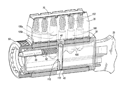
blade defines a longitudinal axis along the length of the blade and is defined
by a first lateral
side and a second lateral side opposite the first lateral side. The blade has
pin engaging
portions at a top of the blade, a first pin groove on the first lateral side
extending in the
direction of the longitudinal axis and defining a first pin surface, and a
second pin groove on
the first lateral side extending in the direction of the longitudinal axis and
defining a second
pin surface. The first pin surface is oriented to face the top of the blade
and the second pin
surface is oriented to face a bottom of the blade such that the first pin
surface and the second
CA 2989223 2017-12-18
WO 2011/053317 PCMS2009/062837
pin surface face in opposite directions. The key and lock cylinder combination
also includes
a housing, an outer pin, a plug, an inner pin, and an auxiliary pin. The
housing includes a
wall that defines a hollow portion, and a pin portion that defines an outer
pin chamber. The
outer pin is disposed in the outer pin chamber. The plug includes a body
rotatably housed
within the hollow portion of the housing, and the housing and the plug
cooperate to define a
shear line. The plug defines a key slot extending at least partially through
the body in a
longitudinal direction of the plug, and the plug further defines an inner pin
chamber disposed
within the body and in communication with the key slot, and an auxiliary pin
chamber in
communication with the key slot. The inner pin chamber is selectively aligned
with the outer
pin chamber. The inner pin is disposed in the inner pin chamber and extends
partially into
the key slot such that the inner pin is engageable by the pin engaging
portions. The auxiliary
pin is disposed in the auxiliary pin chamber and is in communication with the
key slot. The
auxiliary pin includes a first projection defining a first engagement surface
that is engageable
by the first pin surface when the key is inserted into the key slot to move
the auxiliary pin to a
withdrawn position to allow rotation of the plug relative to the housing, and
a second
projection spaced apart from the first projection and defining a second
engagement surface
that generally faces the first engagement surface and that is engageable by
the second pin
surface when the key is removed from the key slot to move the auxiliary pin to
a projecting
position in which the auxiliary pin projects from the plug and is engageable
with the housing
to prevent rotation of the plug relative to the housing.
[0005] In another construction, the invention provides a key and lock
cylinder
combination including a key, a housing, an outer pin, a plug, an inner pin,
and an auxiliary
pin. The key includes a bow and a blade extending from and connected to the
bow, and the
blade defines a longitudinal axis along the length of the blade. The blade is
defined by a first
lateral side and a second lateral side opposite the first lateral side. The
blade has pin
engaging portions at a top of the blade, a first pin surface extending in the
direction of the
longitudinal axis on the first lateral side, and a second pin surface
extending in the direction
of the longitudinal axis on the first lateral side. The first pin surface and
the second pin
surface arc oriented to face in opposite directions, and each of the first pin
surface and the
second pin surface and has an increase in elevation toward the bow when the
longitudinal
axis is horizontal. The housing includes a wall defining a hollow portion, and
a pin portion '
defining an outer pin chamber, The outer pin is disposed in the outer pin
chamber. The plug
includes a body rotatably housed within the hollow portion of the housing, and
the housing
2
CA 2989223 2017-12-18
= =
W02011/053317 PCT/I152009/062837
and the plug cooperate to define a shear line. The plug defines a key slot
extending at least
partially through the body in a longitudinal direction of the plug, and the
plug further defines
an inner pin chamber disposed within the body and in communication with the
key slot and
selectively aligned with the outer pin chamber, The auxiliary pin chamber is
in
communication with the key slot and offset from the key slot. The inner pin is
disposed in
the inner pin chamber and extends into the key slot such that the inner pin is
engageable by
the pin engaging portions. The auxiliary pin is disposed in the auxiliary pin
chamber and is
in communication with the key slot and engaged by the first pin surface upon
insertion of the
key into the key slot to move the auxiliary pin to a withdrawn position to
allow rotation of the
plug relative to the housing. The auxiliary pin also is engaged by the second
pin surface upon
removal of the key from the key slot to move the auxiliary pin to a projecting
position in
which the auxiliary pin projects from the plug and is engageable with the
housing to prevent
rotation of the plug relative to the housing.
[0006] In yet another construction, the invention provides a lock
cylinder including a
housing that has a wall defining a hollow portion, and a pin portion defining
at least two outer
pin chambers. The lock cylinder also includes outer pins disposed in each of
the outer pin
chambers, a plug that has a body rotatably housed within the hollow portion of
the housing,
inner pins, and an auxiliary pin. The housing and the plug cooperate to define
a shear line,
and the plug defines a key slot extending at least partially through the body
in a longitudinal
direction of the plug. The plug further defines at least two inner pin
chambers disposed
within the body and in communication with the key slot and selectively aligned
with the outer
pin chambers, and an auxiliary pin chamber in communication with the key slot.
The inner
pins are disposed in each of the inner pin chambers and extend partially into
the key slot such
that the inner pins are engageable by a key. The auxiliary pin is disposed in
the auxiliary pin
chamber and is in communication with the key slot, and the auxiliary pin
includes a first
projection defining a first engagement surface and a second projection
defining a second
engagement surface. The first engagement surface is engageable by a key to
move the
auxiliary pin to a withdrawn position to allow rotation of the plug relative
to the housing.
The second engagement surface generally faces the first engagement surface and
is
engageable by the key to move the auxiliary pin to a projecting position in
which the
auxiliary pin projects from the plug and is engageable with the housing to
prevent rotation of
the plug relative to the housing.
3
CA 2 98 9223 2 017 -12 -18
663-1746
=
[0007] In yet another construction, the invention provides a key for a
lock cylinder. The .
key includes a bow and a blade extending from and connected to the bow. The
blade defines
a longitudinal axis along the length of the blade and is defined by a first
lateral side and a
second lateral side opposite the first lateral side. The blade has pin
engaging portions at a top
of the blade, a first pin groove that extends in the direction of the
longitudinal axis on the first
lateral side and that defines a first pin surface, and a second pin groove
that extends in the
direction of the longitudinal axis on the first lateral side and that defines
a second pin surface.
The first pin surface is oriented to face the top of the blade and the second
pin surface is
oriented to face a bottom of the blade such that the first pin surface and the
second pin
surface face in opposite directions. Each of the first pin surface and the
second pin surface is
engageable with a pin of the lock cylinder to move the pin between a withdrawn
position and
a projecting position.
[00081 In yet another construction, the invention provides a key for a
lock cylinder. The
key includes it bow and a blade extending from and connected to the bow. The
blade defines
a longitudinal axis along the length of the blade and is defined by a first
lateral side and a
second lateral side opposite the first lateral side: The blade has pin
engaging portions at a top
of the blade, a first pin surface extending in the direction of the
longitudinal axis on the first
lateral side and oriented to face the top of the blade, and a second pin
surface extending in the
direction of the longitudinal axis on the first lateral side and oriented to
face a bottom of the
blade such that the first pin surface and the second pin surface face in
opposite directions.
Each of the first pin surface and the second pin surface has an increase in
elevation toward
the bow when the longitudinal axis is horizontal such that a pin of the lock
cylinder is
movable to a withdrawn position upon insertion of the key into the lock
cylinder, and is
movable to a projecting position upon removal of the key from the lock
cylinder.
= = =
=
=
=
4
CA 2989223 2017-12-18
=
84114006
10008a11 In still another construction, the invention provides a key
and lock cylinder
combination comprising: a key including a bow and a blade extending from and
connected to
the bow, the blade defining a longitudinal axis along the length of the blade
and defined by a
first lateral side and a second lateral side opposite the first lateral side,
the blade having pin
engaging portions at a top of the blade, a first pin groove on the first
lateral side extending in
the direction of the longitudinal axis and defining a first pin surface, and a
second pin groove
on the first lateral side extending in the direction of the longitudinal axis
and defining a
second pin surface, at least a portion of one or both of the first pin surface
and the second pin
surface being planar, the first pin surface oriented to face the top of the
blade and the second
pin surface oriented to face a bottom of the blade such that the first pin
surface and the second
pin surface face in opposite directions, each of the first pin surface and the
second pin surface
having a first portion and a second portion, and each of the first portions
having no elevation
change and each of the second portions having a planar increase in elevation
toward the bow
when the longitudinal axis is horizontal such that an auxiliary pin that is
disposed in an
auxiliary pin chamber is movable upward upon insertion of the key into a key
slot, and
movable downward upon removal of the key from the key slot; a housing
including a wall
defining a hollow portion, and a pin portion defining an outer pin chamber; an
outer pin
disposed in the outer pin chamber; a plug including a body rotatably housed
within the hollow
portion of the housing, the housing and the plug cooperating to define a shear
line, the plug
defining the key slot extending at least partially through the body in a
longitudinal direction of
the plug, the plug further defining an inner pin chamber and disposed within
the body and in
communication with the key slot and selectively aligned with the outer pin
chamber, and the
auxiliary pin chamber in communication with the key slot; an inner pin
disposed in the inner
pin chamber and extending partially into the key slot such that the inner pin
is engageable by
the pin engaging portions; and the auxiliary pin in communication with the key
slot, the
auxiliary pin including a first projection defining a first engagement surface
engageable by the
first pin surface when the key is inserted into the key slot to move the
auxiliary pin to a
withdrawn position to allow rotation of the plug relative to the housing, and
a second
projection spaced apart from the first projection and defining a second
engagement surface
generally facing the first engagement surface and engageable by the second pin
surface when
the key is removed from the key slot to move the auxiliary pin to a projecting
position in
4a
CA 2989223 2019-04-18
84114006
which the auxiliary pin projects from the plug and is engageable with the
housing to prevent
rotation of the plug relative to the housing.
10008131 In still another construction, the invention provides a key and
lock cylinder
combination comprising: a key including a bow and a blade extending from and
connected to
the bow, the blade defining a longitudinal axis along the length of the blade
and defined by a
first lateral side and a second lateral side opposite the first lateral side,
the blade having pin
engaging portions at a top of the blade, a first pin surface extending in the
direction of the
longitudinal axis on the first lateral side, and a second pin surface
extending in the direction of
the longitudinal axis on the first lateral side, the first pin surface and the
second pin surface
oriented to face in opposite directions, and each of the first pin surface and
the second pin
surface having an increase in elevation at respective ends of the first and
second pin surfaces
adjacent the bow when the longitudinal axis is horizontal; a housing including
a wall defining
a hollow portion, and a pin portion defining an outer pin chamber; an outer
pin disposed in the
outer pin chamber; a plug including a body rotatably housed within the hollow
portion of the
housing, the housing and the plug cooperating to define a shear line, the plug
defining a key
slot extending at least partially through the body in a longitudinal direction
of the plug, the
plug further defining an inner pin chamber disposed within the body and in
communication
with the key slot and selectively aligned with the outer pin chamber, and an
auxiliary pin
chamber in communication with the key slot and offset from the key slot; an
inner pin
disposed in the inner pin chamber and extending into the key slot such that
the inner pin is
engageable by the pin engaging portions; and an auxiliary pin disposed in the
auxiliary pin
chamber and in communication with the key slot and engaged by the first pin
surface upon
insertion of the key into the key slot to move the auxiliary pin to a
withdrawn position to
allow rotation of the plug relative to the housing, the auxiliary pin also
engaged by the second
pin surface upon removal of the key from the key slot to move the auxiliary
pin to a projecting
position in which the auxiliary pin projects from the plug and is engageable
with the housing
to prevent rotation of the plug relative to the housing.
[0008c] In still another construction, the invention provides a key for a
lock cylinder,
the key comprising: a bow; and a blade extending from and connected to the
bow, the blade
defining a longitudinal axis along the length of the blade and defined by a
first lateral side and
4b
CA 2989223 2019-04-18
84114006
a second lateral side opposite the first lateral side, the blade having pin
engaging portions at a
top of the blade, a first pin groove extending in the direction of the
longitudinal axis on the
first lateral side and defining a first pin surface, and a second pin groove
extending in the
direction of the longitudinal axis on the first lateral side and defining a
second pin surface, the
first pin surface oriented to face the top of the blade and the second pin
surface oriented to
face a bottom of the blade such that the first pin surface and the second pin
surface face in
opposite directions, each of the first pin surface and the second pin surface
having an increase
in elevation toward the bow when the longitudinal axis is horizontal such that
the pin is
movable upward upon insertion of the key into the lock cylinder, and the pin
is movable
downward upon removal of the key from the lock cylinder, at least one of the
first pin surface
and the second pin surface having a constant increase in elevation over the
length of the at
least one of the first pin surface and the second pin surface, and each of the
first pin surface
and the second pin surface engageable with a pin of the lock cylinder to move
the pin between
a withdrawn position and a projecting position.
[0008d] In still another construction, the invention provides a key for a
lock cylinder,
the key comprising: a bow; and a blade extending from and connected to the
bow, the blade
defining a longitudinal axis along the length of the blade and defined by a
first lateral side and
a second lateral side opposite the first lateral side, the blade having pin
engaging portions at a
top of the blade, a first pin surface extending in the direction of the
longitudinal axis on the
first lateral side and oriented to face the top of the blade, and a second pin
surface extending
in the direction of the longitudinal axis on the first lateral side and
oriented to face a bottom of
the blade such that the first pin surface and the second pin surface face in
opposite directions,
each of the first pin surface and the second pin surface having an increase in
elevation at
respective ends of the first and second pin surfaces adjacent the bow when the
longitudinal
axis is horizontal such that a pin of the lock cylinder is movable to a
withdrawn position upon
insertion of the key into the lock cylinder, and movable to a projecting
position upon removal
of the key from the lock cylinder.
[0009] Other aspects of the invention will become apparent by
consideration of the
detailed description and accompanying drawings.
4c
CA 2989223 2019-04-18
84114006
BRIEF DESCRIPTION OF THE DRAWINGS
[0010] Fig. 1
is a perspective view of a key and lock cylinder combination including a
housing, a plug, and a key embodying the invention.
4d
CA 2989223 2019-04-18
= =
WO 2011/053317 POT/1/52009/062837
[0011] Fig. 2 is a partial cross-section view of the lock cylinder of
Fig. I including the
housing, the plug, the key, and an auxiliary pin.
[0012] Fig. 3 is a perspective view of the housing.
[0013] Fig. 4 is another perspective view of the housing.
[0014] Fig. 5 is a perspective view of the plug.
[0015] Fig. 6 is another perspective view of the plug.
[0016] Fig. 7A is a perspective view of the auxiliary pin.
[0017] Fig. 7B is a side view of the auxiliary pin.
[0018] Fig. 7C is another side view of the auxiliary pin.
[0019] Fig. 7D is an alternative construction of the auxiliary pin.
[0020] Fig. 7E is another alternative construction of the auxiliary pin,
[0021] Fig. 7F is another alternative construction of the auxiliary pin.
[00221 Fig. 70 is another alternative construction of the auxiliary pin.
[0023] Fig. 7H is another alternative construction of the auxiliary pin.
[0024] Fig. 71 is another alternative construction of the auxiliary pin.
[0025] Fig. 7J is another alternative construction of the auxiliary pin.
[0026] Fig. 8 is a perspective view of a blade of the key.
[0027] Fig. 9 is a side view of the blade of Fig. 8.
[0028] Fig. 10 is another perspective view of the key.
[0029] Fig. 11A is a section view of the key taken along line 11A-11A in
Fig. 8.
[0030] Fig. 11B is section view of the key of Fig. 1 taken along line 11B-
11B in Fig. 8.
[0031] Fig. 12 is a section view of the lock cylinder without the key.
CA 2 9 8 9 2 2 3 2 0 1 7 -1 2 -1 8
110 410
W02011/053317 PCT/US2009/062837
[0032] Fig. 13 is the view of Fig. 12 with the key inserted into the key
slot.
[0033] Fig. 14 is a section view of the lock cylinder and the key taken
along the
longitudinal axis of the key.
[0034] Fig. 15 is a perspective view of the key and the auxiliary pin.
[0035] Fig. 16 is another perspective view of the key and the auxiliary
pin.
[0036] Fig. 17 is the view of Fig. 12 With the auxiliary pin in a bumped
position.
[0037] Fig. 18A is a side view of another key for use with the lock
cylinder of Fig. 1.
[00381 Fig. 18B is a side view of another key for use with the lock
cylinder of Fig. I.
[0039] Fig. 18C is a side view of another key for use with the lock
cylinder of Fig. 1.
[0040] Fig. 18D is a side view of another key for use with the lock
cylinder of Fig. 1.
[00411 Fig. I 8E is a side view of another key for use with the lock
cylinder of Fig. 1.
[0042] Fig. 19 is a perspective view of another lock cylinder embodying
the invention.
[0043] Fig. 20 is a section view of the lock cylinder taken along line 20-
20 in Fig. 19.
[0044] Fig. 21 is another section view of the lock cylinder taken along
line 21-21 in Fig.
19.
[0045] Fig. 22 is a perspective view of an alternative construction of
the key of Fig. 1.
DETAILED DESCRIPTION
[00461 Before any embodiments of the invention are explained in detail,
it is to be
understood that the invention is not limited in its application to the details
of construction and
the arrangement of components set forth in the following description or
illustrated in the
following drawings. The invention is capable of other embodiments and of being
practiced
or of being carried out in various ways. Also, it is to be understood that the
phraseology and
terminology used herein is for the purpose of description and should not be
regarded as
limiting. The use of "including," "comprising," or "having" and variations
thereof herein is
6
CA 2989223 2017-12-18
67363-1746
meant to encompass the items listed thereafter and equivalents thereof as well
as additional
items.
[0047] Fig. 1 shows a lock cylinder 10 for use with structures (e.g.,
doors, access panels,
portable locks, etc.) that may be locked and unlocked. Hereinafter, the term
"door" shall be
used to represent all such lockable structures and shall not be construed to
limit the
invention's application solely to doors. The lock cylinder 10 includes a
housing 15 and a
plug 20 that is selectively rotatable within the housing 15 using a key 25.
[0048] As shown in Figs. 1-4, the housing 15 includes a wall 30 and a pin
portion 35.
The wall 30 is substantially cylindrical and defines a hollow portion that is
configured to
receive the plug 20. Figs. 3 and 4 show that the housing 15 includes a first
passageway 40
radially offset from the pin portion 35 and extending through the wall 30, a
second
passageway 45 opposite the first passageway 40, and a third passageway 47
extending
through the wall 30. The first passageway 40 and the second passageway 45 are
aligned with
each other and are in communication with the plug 20 after assembly of the
plug 20 into the
housing 15. The third-passageway 47 is aligned with another passageway (not
shown) on an
opposite portion of the wall for selectively receiving an undercut pin (not
shown) that is
movable into and out of engagement with the housing 15 by the key 25.
[0049] The housing 15 is typically fixed relative to the door, and the
plug 20 is movable
relative to the housing 15 between a locked position and an unlocked position.
The plug 20 is
typically connected to a driver bar (not shown) or other structure via a
retainer or screw cap
50 and an alignment pin 55 biased by a spring 60 (Fig. 2) for moving a latch
relative to the
door to lock or unlock the door. Such arrangements are well known in the art.
100501 As shown in Figs. 1-3 and 12-14, the pin portion 35 extends above
the wall 30 and
includes first or outer pin chambers 65. The outer pin chambers 65 are
accessible through a
removable member 70 adjacent the outer end of the pin portion 35. In the
illustrated
construction, the pin portion 35 includes six outer pin chambers 65, but fewer
or more outer
pin chambers 65 are within the scope of the invention.
[0051] Figs. 1, 2, 5, and 6 show that the plug 20 includes a body 72
rotatable relative to
the hollow portion of the housing 15. The body 72 is defined by a first end
75, a second end
80, and an outer surface 85. The first end 75 is accessible from the front of
the lock cylinder
7
CA 2989223 2017-12-18
67363-1746
10. The second end 80 is accessible from the rear of the lock cylinder 10. As
shown in Figs.
12 and 13, the wall 30 and the outer surface 85 of the plug 20 cooperate to
define a shear line
87.'
[0052j The plug 20 also includes a key slot 90 and second or inner pin
chambers 95. The
key slot 90 extends longitudinally through the body 72 from the first end 75
toward the
second end 80, and is further accessible from adjacent the first end 75. Fig.
14 shows that the
inner pin chambers 95 extend from the outer surface 85 of the body 72 toward
the key slot 90
substantially transverse to the key slot 90. The inner pin chambers 95 are in
communication
with the key slot 90, and are further selectively aligned with respective
outer pin chambers 65
upon insertion of the plug 20 into the housing 15. Thus, Fig. 14 shows that
the plug 20
includes six inner pin chambers 95, although in other constructions the
quantity of inner pin
chambers 95 may be different from the quantity of outer pin chambers 65. While
the inner
and outer pin chambers 65, 95 are shown as substantially cylindrical chambers,
they can have
other shapes (e.g., rectangular, etc.) that are within the scope of the
invention.
[0053] Figs. 2 and 14 show that the pin portion 35 further includes a
respective first or
outer pin 100 disposed within each of the outer pin chambers 65. The outer
pins 100 are
configured to move in a first or inward direction (downward in Fig. 14) into
the plug 20, and
in a second or outward direction (upward in Fig. 14) away from the plug 20.
The outer pins
100 extend partially into the respective inner chambers 95, as shown in Fig.
12, when the
plug 20 is in the locked position and a proper key is not inserted into the
slot 90. In the
illustrated embodiment, the pin portion 35 also include springs 102 to bias
the outer pins 100
inward. In some embodiments, the outer pins 100 can move inward without
engagement by
springs 60 due to orientation of the pin portion 35 above the plug 20 (i.e.,
inward movement
is assisted by gravity). As shown in Figs. 2 and 14, one or more of the outer
pins 100 can be
master key pins 100a, 100b that allow more than one key to lock and unlock the
lock cylinder
10.
[0054] Figs. 2 and 14 show that a respective second or inner pin 105 is
disposed within
each of the inner pin chambers 95. Each inner pin 105 can have a length that
is the same as
or different from the length of the other inner pins 105. Each of the inner
pins 105 is
selectively engaged with the respective outer pin 100, and extends into the
key slot 90.
Generally, the quantity of inner pins 105 will be the same as the quantity of
outer pins 100.
8
CA 2989223 2017-12-18
67363-1746
[0055] In the illustrated construction, the pin portion 35 includes six
outer pins 100 and
six inner pins 105. However more or fewer outer pins 100 and inner pins 105
may be
possible and are within the scope of the invention. For example, commercial
applications of
the plug 20 usually include six outer and inner pins 100, 105, respectively,
in accordance with
established industry practices. However, residential applications of the plug
20 usually have
settled on five outer and inner pins 100, 105, respectively. In these
residential applications, ,
the plug 20 may include five outer pins 100 and inner pins 105 in five
corresponding outer
and inner pin chambers 65, 95, even though the plug 20 may have six or more
outer and inner
pin chambers 65, 95. The remaining outer and inner pin chambers 65, 95 may be
unused in
residential applications. The invention described herein incorporates both
commercial and
residential applications of the lock cylinder 10, and should not be limited to
only one such
application.
[0056] As shown in Fig. 6, the plug 20 further includes an undercut
passageway 107 for receiving an undercut pin (not shown), and a bore or
passageway or
auxiliary pin chamber 110 that extends through the body 72 and that is
parallel to the inner
pin chambers 95. In the illustrated construction, the auxiliary pin chamber
110 is offset from
the key slot 90 in a lateral direction of the plug 20, and is positioned
between two inner pin
chambers 95. In other words, the auxiliary pin chamber 110 is offset from an
adjacent inner
pin chamber 95 in a longitudinal direction of the plug 20. In other
constructions, the
auxiliary pin chamber 110 can be aligned with one inner pin chamber 95 in the
longitudinal
direction of the plug 20.
[0057] Figs. 12, 13, and 17 show that the auxiliary pin chamber 110 is in
direct
communication with the key slot 90. The illustrated plug 20 includes one
auxiliary pin
chamber 110, although more than one auxiliary pin chamber 110 is possible and
considered
herein. For example, other constructions may include auxiliary pin chambers
similar to the
auxiliary pin chamber 110 and auxiliary pins similar to the auxiliary pin 115
but disposed on
the opposite side of the key as the auxiliary pin chamber 110 illustrated in
Fig. 12. In
addition, other constructions could include additional auxiliary pin chambers
and auxiliary
pins located on the same side of the key as the auxiliary pin chamber 110 but
in a different
axial position (e.g., further into the cylinder 10 or closer to the cylinder
face). Thus,
constructions could include two or more auxiliary pins located on one or both
sides of the
9
CA 2989223 2017-12-18
= WO 2011/053317
PCT/US2009/062837
key, as desired. While the illustrated auxiliary pin chamber 110 is
cylindrical, the auxiliary
pin chamber 110 can have other shapes.
[0058] As shown in Figs. 2, 12-14, and 17, a third or auxiliary
pin 115 is disposed in the
auxiliary pin chamber 110 and is in communication with the key slot 90 for
engagement by
the key 25 to move the auxiliary pin 115 between a projecting position (Fig.
12) and a
withdrawn position (Fig. 13). In the projecting position, the auxiliary pin
115 projects from
the plug 20 into the second passageway 45 and is engageable with the housing
15 to prevent
rotation of the plug 20 relative to the housing 15. In the withdrawn position,
the auxiliary pin
115 is lifted and positioned in the plug 20 so that the auxiliary pin 115
clears the shear line 87
or is completely within the plug 20 to allow rotation of the plug 20 relative
to the housing 15.
The auxiliary pin 115 is movable upward and downward (as viewed in Figs. 12
and 13)
relative to the housing 15 and the plug 20, and is unbiased and movable by the
key 25
without a bias or spring force. In some constructions, a biasing member (e.g.,
a spring)
could be positioned to bias the auxiliary pin 115 toward the key 25. As
illustrated in Figs. 12,
13, and 17, the auxiliary pin 115 can cross the shear line 87 in two places
(i.e., the auxiliary
pin 115 can enter either of the first and second passageways 40, 45).
100591 Figs. 7A-7J show that the auxiliary pin 115 includes an
elongated body 120
including a substantially cylindrical upper portion 125 defining a first end
127 and a lower
rectangular or planar portion 130 defining a second end 131. As illustrated in
Fig. 7D, the
upper and lower portions 125, 130 may be substantially cylindrical. As
illustrated in Fig. 7E,
the upper and lower portions 125, 130 may be substantially planar on opposite
sides along the
length of the body 120. In other constructions, the upper and lower portions
125, 130 may
have other shapes.
100601 As shown in Figs. 7A-7E and 7G-71, the first and second
ends 127, 131 are shaped
(e.g., partially curved) to substantially conform to the curvature of the
outer surface 85 of the
plug 20. As illustrated in Figs. 7F and 7J, the first and second ends 127, 131
can include
substantially planar surfaces 132. In other constructions, the first and
second ends 127, 131
may have other shapes or surfaces. For example, Fig. 7J shows that the second
end 131
includes a cylindrical protrusion 133 that extends outward from the body 120
and that is
engageable with the second passageway 45 of the housing 15.
CA 2989223 2017-12-18
S.
1111
W. 2011/053317 PCT/DS2009/062837
100611 The auxiliary pin 115 also includes a first projection 135 and
a second projection
140 spaced apart from the first projection 135 such that there is a void
between the first and
second projections 135, 140. As shown in Figs. 7A-7I, 12, 13, and 17, each of
the first
projection 135 and the second projection 140 extends outward from the lower
portion 130
and is projectable into the key slot 90. The first projection 135 defines a
first engagement
surface 145, and the second projection 140 defines a second engagement surface
150 that
generally faces the first engagement surface 145. As shown in Figs. 7A-7F and
7J, each of
the first projection 135 and the second projection 140 includes a
substantially rectangular
cross-section such that the first and second engagement surfaces 145, 150 are
substantially
planar and parallel to each other.
[0062] In other constructions, the first and second projections 135,
140 may have other
regular or irregular shapes. For example, as shown in Fig. 7G, the first
projection 135 and
the second projection 140 are cylindrically-shaped such that the first and
second engagement
surfaces 145, 150 are curved. As shown in Fig. 7H, the first projection 135
and the second
projection 140 are triangularly-shaped such that the first engagement surface
145 is relatively
narrow or almost linear (corresponding to the point of the triangular-shaped
first projection
135), and the second engagement surface 150 is planar. Fig. 71 shows that the
second
projection 140 can include a chamfered surface 134 that extends outward from
the body 120
and that is engageable by the key 25 upon insertion of the key 25 into the key
slot 90.
[0063] Figs. 8-11B show that the key 25 includes a bow 155 and a
blade 160 extending
from the bow 155. The bow 155 forms a gripping portion that allows a user to
hold and use
the key 25. The blade 160 is insertable into the key slot 90, and extends from
and is
connected to the bow 155. As illustrated in Figs. 8-10, the key 25 defines a
longitudinal axis
165 that extends lengthwise along the blade 160. The blade 160 is defined by a
top 170, a
bottom 175, a first lateral side 180, and a second lateral side 185 that is
opposite the first
lateral side 180. As illustrated in Figs. 8-11B, the longitudinal axis 165 is
horizontal and the
first and second lateral sides 180, 185 are vertical. Although the key 25 is
described in detail
with regard to this orientation, this frame of reference is not limiting. As
one of ordinary skill
in the art will recognize, the key 25 can be turned or oriented in other
directions (e.g., turned
180 degrees such that the top 170 and the bottom 175 of the key 25 are
reversed).
[00641 Figs. 10 and 11A show that the blade 160 includes on the
second lateral side 185
an undercut groove 190 that extends longitudinally along the blade 160. The
undercut groove
11
CA 2 98 9223 2 0 17 -12 -18
=
= wo
2011/053317 PCT/US2009/062837
190 is defined by an undercut surface 195 and is engageable with a portion 200
of the plug 20
(Figs, 12 and 13) as is known in the art. In other constructions, the key 25
may be without
the undercut groove 190.
[00651 Referring to Figs. 8, 9, and 11A-B, the blade 160 includes
pin engaging portions
205 located on the top 170 of the key 25, a first pin groove 210, and a second
pin groove 215.
In the illustrated construction, the first pin groove 210 and the second pin
groove 215 are
formed in the first lateral side 180 using a side bit milling process in which
the side bit mill is
oriented substantially perpendicular to the first lateral side 180. In other
constructions, the
first pin groove 210 and the second pin groove 215 may be formed using other
manufacturing
processes.
[00661 The first and second pin grooves 210 and 215 are generally
non-wavelike grooves
that extend in the direction of the longitudinal axis 165 on the first lateral
side 180 without an
acute undercut into the side of the key. In some constructions, the first
lateral side 180 of the
key 25 may include the one set of pin grooves (e.g., first and second pin
grooves 210, 215)
engageable with the auxiliary pin 115, and the second lateral side 185 of the
key 25 may
include another set of pin grooves engageable with another auxiliary pin
similar to the
auxiliary pin 115. For example, Fig, 22 shows that on the second lateral side
185, the key 25
includes a first pin groove 217 and a second pin groove 218 that are the same
as and
symmetrical to the first pin groove 210 and the second pin groove 215,
respectively. In other
constructions, the first pin groove 217 and the second pin groove 218 can be
different from
and function the same as the respective first and second pin grooves 210, 215.
In the
construction of Fig. 22, the key 25 does not include the undercut groove 190.
Due to the
similarities between the first pin grooves 210, 217 and the second pin grooves
215, 218, the
first and second pin grooves 217, 218 will not be discussed in detail.
[00671 As shown hi. Figs. 8 and 9, the first pin groove 210
extends in the direction of the
longitudinal axis 165 on the first lateral side 180 and has a length that is
shorter than the
length of the blade 160 so that the key 25 can be properly aligned within the
plug. Generally,
the length of the first pin groove can be varied to alter the locking
characteristics of the key
and lock cylinder combination.
[0068] The first pin groove 210 defines a first blade surface 220
and a first pin surface
225. The first blade surface 220 extends vertically on the first lateral side
180 and is oriented
12
CA 2 98 9223 2 0 17 -12 -18
=
= WO
2011/053317 PC171752009/062037
to face outward from the blade 160. The first pin surface 225 is perpendicular
to the first
blade surface and is oriented to face the top 170 of the blade 160, and
extends in the direction
of the longitudinal axis 165. The first pin surface 225 has a change in
elevation 230a when
the longitudinal axis 165 is horizontal. Generally, the change in elevation
230a means that
along the length of the first pin surface 225 from the tip of the key 25
toward the bow 155,
the first pin surface 225 moves closer to the top 170 of the key 25 (i.e., the
change in
elevation 230a is an increase in elevation toward the bow 155). In other
words, the first pin
surface 225 is closer to the top 170 of the key 25 after the change in
elevation 230a.
100691 As shown in Fig. 9, the first pin surface 225 includes a
first portion 235 that is
horizontal, and a second portion 240 that is ramped relative to the first
portion 235. In other
words, the first portion 235 does not have an elevation change and the second
portion 240 has
the change in elevation 230a. In the construction illustrated in Fig. 9, the
first portion 235 of
the first pin surface 225 is planar and the second portion 240 of the first
pin surface 225 is
planar such that the change in elevation 230 of the second portion 240 is
constant over the
length of the second portion 240. In some constructions, the tip of the key 25
can be milled
such that the first portion 235 includes a small ramp (i.e., a non-horizontal
access surface on
the first portion 235) for receiving the auxiliary pin 115 upon initial
insertion of the key 25
into the key slot 90.
[0070] The second pin groove 215 extends in the direction of the
longitudinal axis 165 on
the first lateral side 180 and has substantially the same length as the first
pin groove 210.
Generally, the length of the second pin groove can be varied to alter the
locking
characteristics of the key and lock cylinder combination.
1.00711 The second pin groove?15 defines a second blade surface 245
and a second pin
surface 250. The second blade surface 245 extends vertically on the first
lateral side 180 and
is oriented to face outward from the blade 160. The second pin surface 250 is
perpendicular
to the second blade surface 245 and is oriented to face the bottom 175 of the
blade 160, and
extends in the direction of the longitudinal axis 165 such that the first pin
surface 225 and the
second pin surface 250 face in opposite directions. The second pin surface 250
has a change
in elevation 230h when the longitudinal axis 165 is horizontal (i.e., the
change in elevation
230b is an increase in elevation toward the bow 155). As shown in Fig. 9, the
second pin
surface 250 is parallel to the first pin surface 225. In other constructions,
the second pin
surface 250 may be non-parallel relative to the first pin surface 225.
Generally, the change in
13
CA 2 98 9223 2017-12-18
=
WO 2011/053317 PCT/US2009/062837
elevation 230b of the second pin surface 250 means that along the length of
the second pin
surface 250 from the tip of the key 25 toward the bow 155, the second pin
surface 250 moves '
closer to the top 170 of the key 25. In other words, the second pin surface
250 is closer to the
top 170 of the key 25 after the change in elevation 230b. The change in
elevation 230b
corresponds to the change in elevation 230a associated with the first pin
surface 225 and is
separated from the first pin surface 225 based on the distance between the
first and second'
projections 135, 140 of the auxiliary pin 115.
[00721 The second pin surface 250 includes a first portion 255 that is
horizontal, and a
second portion 260 that is ramped relative to the first portion 255. In other
words, the first
portion 255 has no elevation change and the second portion 260 has the change
in elevation
230b. In the construction illustrated in Fig. 9, the first portion 255 of the
second pin surface
250 is planar and the second portion 260 of the second pin surface 250 is
planar such that the
change in elevation 230b is constant over the length of the second portion
240. In this
construction, the first portions 235, 255 of the respective first and second
pin surfaces 225,
250 are parallel to each other, and the second portions 240, 260 of the
respective first and
second pin surfaces 225, 250 are parallel to each other. In other
constructions, one or both of
the first portions 235, 255 and the second portions 240, 260 of the respective
first and second
pin surfaces 225, 250 may be non-parallel relative to each other.
100731 The lock cylinder 10 is assembled by inserting the inner pins 105
into the inner
pin chambers 95 from adjacent a top of the plug 20 (Fig. 5), and inserting the
auxiliary pin
115 into the auxiliary pin chamber 110 from adjacent a bottom of the plug 20
(Fig. 6). The
plug 20 is then inserted into the housing 15 after the inner pins 105 and the
auxiliary pin 115
have been positioned in the plug 20. The outer pins 100 are positioned in the
outer pin
chambers 65 after the plug 20 has been assembled and inserted into the housing
15. The
springs 102 are inserted into the pin portion 35 after insertion of the outer
pins 100,to bias the
outer pins 100 and the inner pins 105 inward such that the outer pins 100
partially extend into
the inner pin chambers 95. Assembly of the remaining components of the lock
cylinder 10 is
well known to those skilled in the art.
[0074] Fig. 12 shows the lock cylinder 10 without a key in the key slot
90. Without a key
in the key slot 90, the auxiliary pin 115 is in the projecting position such
that the second end
131 of the auxiliary pin 115 is disposed in the second passageway 45 and is
engageable with
the housing 15 to prevent rotation of the plug 20 relative to the housing 15.
The second
14
CA 2 9 8 9 2 2 3 2 0 1 7 -1 2 -1 8
67363-1746
projection 140 is positioned at the bottom of the key slot 90 and rests on the
wall 30 to limit
downward movement of the auxiliary pin 115 through the housing 15 and the plug
20. The
= second end 131 of the auxiliary pin 115 is engaged with the housing 15
within the second
passageway 45 in response to partial rotation of the plug 20.
[00751 Figs. 13 and 14 show the lock cylinder 10 with the key 25 (a
proper or correct
key) inserted into the key slot 90 and the auxiliary pin 115 in the withdrawn
position. The
pin engaging portions 205 of the key 25 are engaged with each of the inner
pins 105 to move
the outer pins 100 to the shear line 87. Once the outer pins 100 are moved to
the shear line
87, the plug 150 can be rotated between locked and unlocked positions.
[0076] When the key 25 is inserted in the key slot 90, the first
engagement surface 145 is
engaged by the first pin surface 225 to move the auxiliary pin 115 to the
withdrawn position
to allow rotation of the plug 20 relative to the housing 15. Figs. 15 and 16
show that as the
key 25 is inserted into the key slot 90, the first engagement surface 145
slides on the first pin
surface 225 to move the auxiliary pin 115 to the withdrawn position (Fig. 13).
Fig. 16 shows
that the first projection 135, and therefore the auxiliary pin 115, slides on
the first portion 235
without vertical movement. Fig. 15 shows that the auxiliary pin 115 moves
upward toward
the top 170 of the key 25 as the first projection 135 slides on the second
portion 240 during
insertion of the key 25 into the key slot 90 due to the change in elevation
230a of the first pin
surface 225. The change in elevation 230a moves the auxiliary pin 115 upward
so that when
the key 25 is fully inserted into the key slot 90, the auxiliary pin 115 is in
the withdrawn
position.
100771 As shown in Fig. 14, the location of the change in elevation 230a
corresponds to
the upward movement necessary for the auxiliary pin 115 to reach the withdrawn
position
without moving the upper portion 125 of the auxiliary pin 115 into the first
passageway 40.
Therefore, the lengths of the first pin 210 groove and the second pin groove
215 depend at
least in part on the location of the auxiliary pin 115 within the plug 20. In
the illustrated
construction, the auxiliary pin 115 is located between the third and fourth
inner pins 100, and
the locations and elevation changes of the changes in elevation 230a, 230b
correspond to the
location of the auxiliary pin 115 and the elevation change necessary to move
the auxiliary pin
115 to the withdrawn position, respectively. As shown in Fig. 13, when the
auxiliary pin 115
is in the withdrawn position, the plug 20 can be rotated relative to the
housing 15.
CA 2989223 2017-12-18
S
WO 2011/053317 PC1702009/062837
100781 When the key 25 is removed from the key slot 90, the second
engagement surface
150 is engaged by the second pin surface 250 to move the auxiliary pin 115 to
the projecting
position in which the auxiliary pin 115 projects from the plug 20 and is
engageable with the
housing 15 within the second passageway 45 to prevent rotation of the plug 20
relative to the
housing 15. As the key 25 is removed from the key slot 90, the second
engagement surface
150 is engaged by and at least initially slides on the second pin surface 250
(Fig. 15). In the
illustrated construction, the first engagement surface 145 then slides on the
remainder of the
first pin surface 225 during removal of the key 25 after the second engagement
surface 150 is
initially engaged by the second pin surface 250. Alternatively, the auxiliary
pin 115 may
slide on the first pin surface 225 without initially sliding on the second pin
surface 250 (e.g.,
when the force of gravity overcomes frictional resistance between the plug 20,
the auxiliary
pin chamber 110, and the auxiliary pin.115).
[0079] As shown in Fig. 15, the auxiliary pin 115 moves downward to the
projecting
position on one or both of the second portions 240, 260 along the changes in
elevation 230a,
230b. As shown in Fig. 16, the auxiliary pin 115 then slides along the first
portion 235 of the
first pin surface 225 until the key 25 is removed from the key slot 90. When
the key 25 is
completely removed from the key slot 90, the auxiliary pin 115 is returned to
the projecting
position. As a corollary to the concept that the changes in elevation 230a,
230b correspond to
the upward movement necessary for the auxiliary pin 115 to reach the withdrawn
position,
the changes in elevation 230a, 230b correspond to the downward movement
necessary for the
auxiliary pin 115 to reach the projecting position. As shown in Fig. 12, when
the auxiliary
pin 115 is in the projecting position, rotation of the plug 20 relative to the
housing 15 is
prevented.
[0080] Fig. 17 shows the auxiliary pin 115 in a bumped position after
being bumped by
an inappropriate key or other improper or subversive tool (not shown). Due to
the through-
hole nature of the first and second passageways 40,45 and the auxiliary pin
chamber 110, the
auxiliary pin 115 is movable upward and downward such that the auxiliary pin
115 can
engage two different portions of the shear line 87 depending on the direction
of movement.
In the bumped position, the auxiliary pin 115 projects upward (as viewed in
Fig. 17) into the
first passageway 40 of the housing 15 such that the upper portion 125 of the
auxiliary pin 115
is engageabIe with the housing 15 to prevent rotation of the plug 20 relative
to the housing
15.
16
CA 2989223 2017-12-18
4110
WO 2011/053317
PC171.152009/062837
[00811 Although the invention is described in detail below with regard to
the lock
cylinder 10 and the key 25, one of ordinary skill in the art will recognize
that other lock
cylinders and keys are within the scope of the invention.
[0082] For example, Figs. 18A-18E show alternative keys 265a-e embodying
the
invention. Except as described below, the keys 265a-e are similar to and
function the same as
the key 25, and common elements have the same reference numerals.
[0083] Fig. 18A shows that the key 265a includes a first pin groove 270
defining a first
pin surface 275 and a second pin groove 280 defining a second pin surface 285.
The first pin
surface 275 includes a first portion 290 and a second portion 292, and the
second pin surface
285 includes a first portion 293 and a second portion 295. Each of the first
portions 290, 292
is horizontal and each of the second portions 293, 295 is curved such that the
respective
changes in elevation 230a, 230b are non-planar or curvilinear. As shown in
Fig. 18A, the
first pin surface 275 and the second pin surface 285 are parallel to each
other.
[00841 Fig. 18B shows that the key 265b includes a first pin groove 300
defining a first
pin surface 305 and a second pin groove 310 defining a second pin surface 315.
Each of the
first and second pin surfaces 305, 315 are planar such that the respective
changes in elevation
230a, 230b are constant and extend over the length of the first and second pin
surfaces 305,
315. As shown in Fig, 18B, the first pin surface 275 and the second pin
surface 285 are
parallel to each other.
[0085] Fig. 18C shows that the key 265c includes a first pin groove 320
defining a first
pin surface 325 and a second pin groove 330 defining a second pin surface 335.
Each of the
first and second pin surfaces 325, 335 are curved such that the respective
changes in elevation
230a, 230b are non-planar or curvilinear and extend over the length of the
first and second
pin surfaces 325, 335. As shown in Fig. 18C, the first pin surface 325 and the
second pin
surface 335 are parallel to each other.
[0086] Fig. 18D shows that the key 265d includes a first pin groove 340
defining a first
pin surface 345 and a second pin groove 350 defining a second pin surface 355.
The first pin
surface 345 includes a first portion 360, a second portion 361, and a third
portion 362. The
second pin surface 355 includes a first portion 363, a second portion 364, and
a third portion
365. Each of the second portions 361 ,364 is located adjacent a middle of the
respective first
17
CA 2 98 9223 2017-12-18
= 110
W02011/053317 PCT/1J52009/062837
and second pin grooves 340, 350, and is ramped relative to the associated
first portion 360,
363 and the associated third portion 362, 365. Each of the first portions 360,
363 and each of
the respective third portions 362, 365 is horizontal, and each of the second
portions 361, 364
is planar such that the respective changes in elevation 230a, 230b are
constant. As shown in
Fig. 18D, the first pin surface 275 and the second pin surface 285 are
parallel to each other.
[0087] Fig. 18E shows that the key 265e includes a first pin groove 370
defining a first
pin surface 375 and a second pin groove 380 defining a second pin surface 385.
The first pin
surface 375 includes a first portion 390, a second portion 391, and a third
portion 392. The
second pin surface 385 includes a first portion 393, a second portion 394, and
a third portion
395. Each of the second portions 391,394 is located adjacent a middle of the
respective first
and second pin grooves 370, 380, and is ramped relative to the associated
first portion 390,
393 and the associated third portion 392, 395. Each of the first portions 390,
393 and each of
the third portions 362, 365 is horizontal, and each of the second portions
361, 364 is curved
such that the respective changes in elevation 230a, 230b are curvilinear. As
shown in Fig.
18E, the first pin surface 275 and the second pin surface 285 are parallel to
each other.
[0088] Although various constructions of keys for the lock cylinder 10
have been
described herein, one of ordinary skill in the art will recognize that keys
including other
changes in elevation are possible and within the scope of the invention. For
example,
changes in elevation on a key may be located adjacent the tip of the key.
Furthermore, more
than one change in elevation may be provided on a key, either toward a top of
the key, toward
a bottom of the key, or both (e.g., stepped changes in elevation).
[0089] By way of illustration, the invention described herein is
applicable to and usable
with other lock cylinders. For example, Figs. 19-21 show another construction
of a lock
cylinder 410 and a key 415 for use with the door. The lock cylinder 410 is an
interchangeable core ("IC") lock cylinder including an IC housing 420 and a
plug 425 that is
lockable and unlockable using the key 415. Except as described below, the lock
cylinder 410
is similar to the lock cylinder 10 described with regard to Figs. 1-17 and the
key 415 is
similar to the key 425, and common elements are given the same reference
numerals.
[0090] Figs. 19-21 show how the invention described herein can be used
with an
interchangeable core lock cylinder. One of ordinary skill in the art will
recognize the features
18
CA 2 98 92 2 3 2 017 -12 -18
=
WO 2011/053317 PCT/U52009/062837
and elements of the IC lock cylinder 410, and as such, these features will not
be described in
detail.
[00911 As shown in Figs. 20 and 21, the key 415 includes a bow 430 that
is similar to the
bow 155 and a blade 435 that is similar to the blade 160 described with regard
to Figs. 8-11B.
The blade 435 includes a first pin groove 440 and a second pin groove 445 that
extend in the
direction of the longitudinal axis a substantial length of the blade 435
without extending the
full length of the blade 435. As shown in Fig, 21, the first pin groove 440
and the second pin
groove 445 are formed in the first lateral side 180.
[0092] The first pin groove 440 defines a first pin surface 450 that is
oriented to face the
top 170 of the blade 440. The first pin surface 450 extends in the direction
of the longitudinal
axis 165 and has a change in elevation 455a when the longitudinal axis 165 is
horizontal. As
shown in Fig. 21, the first pin surface 450 includes a first portion 460 that
is horizontal, and a
second portion 465 that is ramped relative to the first portion 460 to define
the change in
elevation 455a.
[00931 The second pin groove 445 defines a second pin surface 470 that is
oriented to
face the bottom 175 of the blade 435 such that the first pin surface 450 and
the second pin
surface 470 face in apposite directions. The second pin surface 470 extends in
the direction
of the longitudinal axis 165 and has a change in elevation 455b when the
longitudinal axis
165 is horizontal. Fig. 21 shows that the second pin surface 470 includes a
first portion 475
that is horizontal, and a second portion 480 that is ramped relative to the
first portion 475 to
define the change in elevation 455b. As shown in Fig. 21, each of the first
portions 460, 475
is planar and each of the second portions 465, 480 is planar such that the
changes in elevation
455a, 455b are constant. In the illustrated construction, the second pin
surface 470 is parallel
to the first pin surface 450, and the change in elevation 455b corresponds to
the change in
elevation 455a associated with the first pin surface 450.
[0094] Various features and advantages of the invention are set forth in
the following
claims.
19
CA 2 98 9223 2 017 -12 -18