Note: Descriptions are shown in the official language in which they were submitted.
CIRCULATION VALVE
CROSS-REFERENCE TO RELATED APPLICATIONS
[0ool] This application claims benefit of U.S. provisional patent application
Serial No.
62/182,282 filed June 19, 2015, and entitled "Annulus Boost Valve."
STATEMENT REGARDING FEDERALLY SPONSORED
RESEARCH OR DEVELOPMENT
[0ool] Not applicable.
BACKGROUND
[0002] This disclosure generally relates to tools for use in a borehole
extending into a
subterranean formation. More particularly, the disclosure relates to downhole
tools for
boosting annulus flow in the borehole as part of an oilfield drilling
operation of a well
system.
[0003] Drilling operations may produce a borehole having a cross-sectional
diameter that
varies along the borehole's length. Particularly, the borehole may have a
diameter that is
larger near the surface and is gradually reduced moving along the length of
the borehole
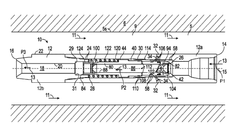
towards the toe or bottom of the borehole. For instance, the borehole diameter
may change in
size between casing or liner tubular members of different diameters that line
the inner surface
of the borehole. Some oilfield drilling operations include a drill string that
extends through
the borehole and terminates at a drill bit disposed at the bottom of the
borehole for cutting
into the subterranean formation into which the borehole extends.
[0004] In some such drilling operations, drilling fluid or mud may be pumped
down through
a central passage of the drill string from mud pumps disposed at the surface
to the drill bit,
where the pumped mud may cool the drill bit and circulate entrained drill
cuttings to the
surface through an annular flowpath formed between the borehole wall and the
drillstring.
Due to the varying cross-sectional diameter of the borehole along its axial
length, the cross-
sectional area of the annular flowpath may vary along the axial length of the
borehole, with
the annular flowpath having a larger cross-sectional area near the surface
than towards the
bottom of the borehole by the drill bit. As the drilling mud and entrained
drill cutting flow
upwards through the annular flowpath, the flow speed of the returning fluid,
commonly
known as annulus velocity (AV), may decrease in response to the increasing
cross-sectional
area of the annular flowpath moving towards the surface. Moreover, if the AV
decreases by a
1
Date recue/Date received 2023-04-21
CA 02990002 2017-12-18
WO 2016/205725
PCT/US2016/038200
sufficient degree, the AV may drop below the slip velocity of the returning
fluid, causing the
entrained drill cuttings to settle out of the recirculating mud, thereby
inhibiting the
recirculating mud from carrying the drill cuttings to the surface for removal
from the
borehole.
BRIEF SUMMARY OF THE DISCLOSURE
[0005] An embodiment of a circulation valve comprises a housing having a
throughbore and
a housing port, and a sliding sleeve disposed in the throughbore of the
housing and having a
first radial port, wherein the sliding sleeve comprises a first jet configured
to provide a first
pressure drop in a fluid flowing therethrough, and disposed in a throughbore
of the sliding
sleeve, and a second jet configured to provide a second pressure drop in a
fluid flowing
therethrough, wherein the second jet is disposed in the throughbore of the
sliding sleeve and
is axially spaced from the first jet, wherein, when the sliding sleeve is
disposed in a first
position, fluid flow between the throughbore of the sliding sleeve and the
housing port is
restricted, and when the sliding sleeve is disposed in a second position,
fluid flow between
the throughbore of the sliding sleeve and the housing port is permitted,
wherein the sliding
sleeve is actuated between the first and second positions in response to a
change in a flowrate
of a fluid flow passing through the circulation valve. In some embodiments,
the first jet and
the second jet are each configured to allow for the passage of a tool
therethrough. In some
embodiments, when the sliding sleeve is in the second position, fluid
communication is
provided between the throughbore of the sliding sleeve and an annular flowpath
surrounding
the circulation valve. In certain embodiments, the circulation valve further
comprises a
biasing member disposed in the throughbore of the housing between an annular
shoulder of
the sliding sleeve and an annular shoulder of the housing to exert a biasing
force against the
sliding sleeve. In certain embodiments, in response to a first flow rate of
fluid flowing
through the circulation valve, the biasing member retains the sliding sleeve
in the first
position, in response to a second flow rate of fluid flowing through the
circulation valve, the
sliding sleeve is actuated from the first position to the second position; and
the second flow
rate is greater than the first flow rate. In some embodiments, the sliding
sleeve is actuated
from the first position to the second position in response to a pressure force
applied to the
sliding sleeve from the first pressure drop and the second pressure drop in a
fluid flow
through the first jet and the second jet. In some embodiments, a jet is
disposed in the housing
port configured to provide a pressure drop in a fluid flowing therethrough. In
certain
embodiments, the sliding sleeve further comprises an annular groove extending
into an outer
2
CA 02990002 2017-12-18
WO 2016/205725
PCT/US2016/038200
surface of the sliding sleeve, wherein the annular groove is axially aligned
with the first radial
port.
[00061 An embodiment of a circulation valve comprises a housing having a
throughbore and
a housing port having a jet disposed therein, wherein the jet is configured to
provide a
pressure drop in a fluid flowing therethrough, and a sliding sleeve disposed
in the
throughbore of the housing, wherein the sliding sleeve comprises a throughbore
and a first
radial port, wherein, when the sliding sleeve is disposed in a first position,
fluid flow between
the throughbore of the sliding sleeve and the housing port is restricted,
wherein, when the
sliding sleeve is disposed in a second position, fluid flow between the
throughbore of the
sliding sleeve and the housing port is permitted, wherein, in response to a
fluid flow through
the circulation valve, a first pressure drop is created in the fluid flow at a
first flow restriction
disposed in the throughbore of the sliding sleeve, and a second pressure drop
is created in the
fluid flow at a second flow restriction disposed in the throughbore of the
sliding sleeve. In
some embodiments, the sliding sleeve is actuated between the first and second
positions in
response to a change in a flowrate of a fluid flow passing through the
circulation valve, and
the jet disposed in the housing port is configured to divert a preselected
portion of the fluid
flow entering the circulation valve through the first radial port of the
sliding sleeve. In some
embodiments, the first pressure drop is greater than the second pressure drop.
In certain
embodiments, the sliding sleeve further comprises a first jet disposed in the
throughbore of
the sliding sleeve, wherein the first jet configured to provide the first
pressure drop in
response to the fluid flow, and a second jet disposed in the throughbore of
the sliding sleeve
and axially spaced from the first jet, wherein the second jet configured to
provide the second
pressure drop in response to the fluid flow. In some embodiments, the first
jet and the second
jet are each configured to allow for the passage of a tool therethrough. In
some
embodiments, when the sliding sleeve is in the second position, fluid
communication is
provided between the throughbore of the sliding sleeve and an annular flowpath
surrounding
the circulation valve. In certain embodiments, the circulation valve further
comprises a
biasing member disposed in the throughbore of the housing between an annular
shoulder of
the sliding sleeve and an annular shoulder of the housing, wherein the biasing
member is
configured to exert a biasing force against the sliding sleeve. In certain
embodiments, the
sliding sleeve further comprises a second radial port configured to provide
fluid
communication between the throughbore of the sliding sleeve and a first
annular shoulder of
the sliding sleeve, and a plurality of circumferentially spaced slots
extending radially into an
outer surface of the sliding sleeve, wherein the slots are configured to
provide fluid
3
CA 02990002 2017-12-18
WO 2016/205725
PCT/US2016/038200
communication between a second annular shoulder of the sliding sleeve and the
throughbore
of the housing.
[0007] An embodiment of a method of controlling fluid flow through a
circulation valve
disposed in a borehole comprises flowing a fluid at a first flowrate through a
first jet and a
second jet disposed in a throughbore of a sliding sleeve disposed in a housing
of the
circulation valve, flowing the fluid at a second flowrate through the first
jet and the second jet
to actuate the sliding sleeve from a first position to a second position, and
flowing the fluid
from the throughbore of the sliding sleeve through a housing port of the
housing in response
to actuating the sliding sleeve from the first position to a second position.
In some
embodiments, the method further comprises producing a first pressure drop in
the fluid flow
as the fluid passes through the first jet, and producing a second pressure
drop in the fluid flow
as the fluid passes through the second jet. In certain embodiments, the
circulation valve
further comprises producing a pressure force on the sliding sleeve to actuate
the sliding
sleeve from the first position to the second position in response to producing
the first pressure
drop and the second pressure drop in the fluid flow. In certain embodiments,
the first
pressure drop is greater than the second pressure drop.
BRIEF DESCRIPTION OF THE DRAWINGS
100081 For a detailed description of the various exemplary embodiments
disclosed herein,
reference will now be made to the accompanying drawings in which:
[0009] Figure 1 is a schematic view of an embodiment of a drilling system in
accordance
with principles disclosed herein;
[0010] Figure 2 illustrates a side cross-sectional view of an embodiment of a
circulation
valve of the drilling system of Figure 1 in a first position in accordance
with principles
disclosed herein;
[0011] Figure 3 is a side cross-sectional view of an embodiment of a valve
sleeve of the
circulation valve shown in Figure 2 in accordance with principles disclosed
herein; and
[0012] Figure 4 is a cross-sectional view along line 4-4 of Figure 3 of the
valve sleeve shown
in Figure 5;
[0013] Figure 5 is a perspective view of an embodiment of a sliding sleeve of
the circulation
valve shown in Figure 2 in accordance with principles disclosed herein;
[0014] Figure 6 is a side cross-sectional view of the sliding sleeve shown in
Figure 5;
[0015] Figure 7 is a zoomed-in side cross-sectional view of an embodiment of a
first jet of
the sliding sleeve shown in Figure 5 in accordance with principles disclosed
herein;
4
CA 02990002 2017-12-18
WO 2016/205725
PCT/US2016/038200
[00161 Figure 8 is a zoomed-in side cross-sectional view of an embodiment of a
second jet of
the sliding sleeve shown in Figure 5 in accordance with principles disclosed
herein;
[0017] Figure 9 illustrates a side cross-sectional view of the circulation
valve of Figure 2 in a
second position in accordance with principles disclosed herein; and
[0018] Figure 10 is a side cross-sectional view of another embodiment of a
circulation valve
of the drilling system of Figure 1 in accordance with principles disclosed
herein.
DETAILED DESCRIPTION OF EXEMPLARY EMBODIMENTS
[00191 The following discussion is directed to various embodiments of the
disclosure. One
skilled in the art will understand that the following description has broad
application, and the
discussion of any embodiment is meant only to be exemplary of that embodiment,
and not
intended to intimate that the scope of the disclosure, including the claims,
is limited to that
embodiment.
[0020] The drawing figures are not necessarily to scale. Certain features of
the disclosure
may be shown exaggerated in scale or in somewhat schematic form, and some
details of
conventional elements may not be shown, all in the interest of clarity and
conciseness. In the
following discussion and in the claims, the terms "including" and "comprising"
are used in an
open-ended fashion, and thus should be interpreted to mean "including, but not
limited to... ."
Also, the term "couple" or "couples" is intended to mean either an indirect or
direct
connection. Thus, if a first device couples to a second device, that
connection may be
through a direct connection, or through an indirect connection via other
devices and
connections.
[0021] Referring now to Figure 1, a downhole drilling system 1 comprises a rig
2, a drill
string 3 having a bottom hole assembly (BHA) 4 coupled to a lower end thereof.
Drill string
3 extends through a wellbore 5 drilled into a subterranean formation 6. In the
embodiment
shown in Figure 1, wellbore 5 includes surface casing 7 extending downwards
from the
surface. BHA 4 generally includes components of the drill string 3 for
drilling the wellbore
5. Particularly, the BHA 4 includes a drill bit 8 that engages the formation 6
and other
components for powering and orienting the drill bit 8, such as a mud motor,
drill collars,
stabilizers, and the like. Drilling fluid or mud is pumped down the drill
string 3 and through
the downhole motor of BHA 20, eventually passing out of the drill bit 8
through nozzles
positioned in the bit face. The drilling fluid cools the drill bit 8 and
flushes cuttings away
from the face of drill bit 8. The drilling fluid and cuttings are forced from
the bottom 5b of
CA 02990002 2017-12-18
WO 2016/205725
PCT/US2016/038200
the wellbore 5 to the surface 6s through an annulus 9 formed between the drill
string 3 and
the wellbore sidewall 5s.
100221 In the embodiment shown in Figure 1, the annulus 9 of the portion of
the wellbore 5
disposed in surface casing 7 has a larger cross-sectional area than the
annulus 9 of the portion
of wellbore 5 disposed between a lower end or bottom 7b of surface casing 7
and the bottom
5b of wellbore 5. Further, in this embodiment drill string 3 comprises an
annulus boost or
circulation valve 10 disposed in the portion of wellbore 5 surrounded by
surface casing 7,
Although drill string 3 is illustrated as having a circulation valve 10
disposed within surface
casing 7, in other embodiments drill string 3 may comprise a circulation valve
10 disposed
near BHA 4, or multiple circulation valves 10 disposed at different intervals
along drill string
3. Circulation valve 10 is configured to selectably divert fluid from an
internal bore of drill
string 3 to the annulus 9. In some embodiments, circulation valve 10 of drill
string 3 is
configured to boost the velocity of fluid flowing through the annulus 9 of
wellbore 5.
Particularly, in certain embodiments circulation valve 10 is configured to
prevent the fluid
flow through the annulus 9 from dropping below a slip velocity as the cross-
sectional area of
wellbore 5 decreases moving from the bottom 5b of wellbore 5 towards the
surface 6s.
[00231 Referring to Figure 2, an embodiment of circulation valve 10 of
drilling system 1 is
shown. Particularly, Figure 2 illustrates circulation valve 10 in a first or
closed position. In
the embodiment shown in Figure 2, circulation valve 10 has a central or
longitudinal axis 15
and generally includes an outer housing 12, a valve sleeve 40, and a sliding
sleeve 80, where
valve sleeve 40 and sliding sleeve 80 are disposed within a throughbore 18 of
the housing 12.
In this embodiment, circulation valve 10 is generally configured to provide
selectable fluid
communication between throughbore 18 of housing 12 and annulus 9. Circulation
valve 10 is
further configured to selectably increase or adjust the annular velocity (AV)
of fluid flowing
through the annulus 9 along an annular flowpath 11.
[00241 Housing 12 of circulation valve 10 is generally tubular and includes a
first or upper
box end 14 and a second or lower pin end 16. Throughbore 18 of housing 12
extends
between upper end 14 and lower end 16 and is defined by a generally
cylindrical inner
surface 20. Both upper end 14 and lower end 16 of housing 12 are equipped with
threaded
couplers for forming threaded connections with adjoining tubular members (not
shown).
Housing 12 also includes a generally cylindrical outer surface 22, where
annulus 9 extends
radially between the wellbore sidewall 5s and outer surface 22 of housing 12.
Further,
housing 12 comprises a first or upper tubular section 12a and a second or
lower tubular
section 12b coupled to upper section 12a via a threaded connection or joint
disposed
6
CA 02990002 2017-12-18
WO 2016/205725
PCT/US2016/038200
therebetween. Fluid communication between annulus 9 and throughbore 18 is
restricted by
an annular seal 24 disposed radially between lower tubular section 12b and
upper tubular
section 12a. Although in the embodiment shown in Figure 2 housing 12 includes
upper and
lower sections 12a and 12b, in other embodiments, housing 12 may comprise a
single, unitary
tubular member.
[0025] In this embodiment, the inner surface 20 of housing 12 includes an
upper annular
shoulder 26 facing lower end 16 and a first lower annular shoulder 28 facing
upper end 14
and axially spaced from upper shoulder 26. Inner surface 20 of housing 12 also
includes a
second lower annular shoulder 29 facing upper end 14 and disposed axially
between first
lower shoulder 28 and lower end 16. First lower shoulder 28 and second lower
shoulder 29
define the axial ends of a reduced diameter segment 31 of the inner surface 20
of housing 12,
which receives a lower end of sliding sleeve 80. In addition, housing 12
further includes a
plurality of circumferentially spaced radial or housing ports 32 disposed
between upper
shoulder 26 and lower shoulder 28 and extending obliquely between inner
surface 20 and
outer surface 22. Particularly, ports 32 of housing 12 are angled uphole such
that an acute
angle is formed between each port 32 and the annular flowpath 11. However,
although in the
embodiment shown in Figure 2 ports 32 are angled uphole, in other embodiments
ports 32
may be angled in other directions with respect to annulus 9.
[0026] In the embodiment shown in Figure 2, each port 32 includes a jet 34
configured to
produce a flow restriction or pressure differential on fluid flowing
therethrough. Jets 34 are
releasably coupled to housing 12, and thus, may be removed and replaced from
housing 12
and circulation valve 10. As will be discussed further herein, the flow
restriction provided by
jets 34 in ports 32 may be adjusted depending upon operating conditions and
preferred flow
distribution. For instance, jets 34 may be adjusted to provide a preferred
distribution of fluid
flow through circulation valve 10 when circulation valve is actuated into a
second or open
position. Particularly, jets 34 may be adjusted to determine the portion of
fluid flow entering
throughbore 18 at upper end 14 that flows into the annulus 9 via ports 32, and
the portion of
fluid flow entering throughbore 18 at upper end 14 that exits throughbore 18
at lower end 16
and continues to flow through the drill string 3 (not shown) coupled with
circulation valve 10.
[0027] Referring to Figures 2-4, valve sleeve 40 of circulation valve 10 is
generally tubular
and includes a first or upper end 42, a second or lower end 44, and a
throughbore 46
extending between ends 42 and 44. In this arrangement, throughbore 46 of valve
sleeve 40 is
defined by a generally cylindrical inner surface 48. Valve sleeve 40 is
disposed in
throughbore 18 of housing 12 between upper shoulder 26 and lower shoulder 28,
with upper
7
CA 02990002 2017-12-18
WO 2016/205725
PCT/US2016/038200
end 42 of valve sleeve 40 in engagement or disposed directly adjacent upper
shoulder 26.
Valve sleeve 40 also includes a generally cylindrical outer surface 50 having
a female
threaded connector disposed thereon configured to threadably couple with a
corresponding
threaded coupler disposed on the inner surface 20 of housing 12, forming a
threaded
connection 30 (shown in Figure 2) therebetween to axially and rotationally
lock valve sleeve
40 to housing 12 of circulation valve 10.
[0028] In the embodiment shown in Figures 2-4, outer surface 50 of valve
sleeve 40 includes
an annular groove 54 extending therein and disposed proximal upper end 42.
Annular groove
54 is in fluid communication with a plurality of circumferentially spaced
radial ports 56
extending obliquely between inner surface 48 and outer surface 50 of valve
sleeve 40.
Particularly, ports 56 of valve sleeve 40 are angled uphole with respect to
annulus 9.
However, although in the embodiment shown in Figure 2 ports 56 are angled
uphole, in other
embodiments ports 56 may be angled in other directions with respect to annulus
9. In this
embodiment, annular groove 54 of valve sleeve 40 is in fluid communication
with ports 32 of
housing 12, thereby providing a path of fluid communication between ports 56
of valve
sleeve 40 and ports 32 of housing 12 irrespective of the relative angular
orientation of valve
sleeve 40 relative housing 12. Additionally, valve sleeve 40 includes a pair
of axially spaced
annular seals or seal assemblies 58 disposed in corresponding annular grooves
extending into
the outer surface 50 of valve sleeve 40. Particularly, one pair of annular
seals 58 is disposed
proximal each axial end of annular groove 54. Annular seals 58 of valve sleeve
40 fluidically
isolate annular groove 54 from the rest of throughbore 18, restricting fluid
flow between
annular groove 54 of valve sleeve 40 and throughbore 18 of housing 12.
[0029] In the embodiment shown in Figures 2-4, the inner surface 48 of valve
sleeve 40
includes a chamfered surface 60 at upper end 42 for directing a fluid flow
into throughbore
46. Additionally, inner surface 48 of valve sleeve 40 includes an annular
upper shoulder 62
disposed proximal upper end 42 and facing the lower end 44 of valve sleeve 40.
Upper
shoulder 62 of valve sleeve 40 is configured to restrict or delimit relative
axial movement
between valve sleeve 40 and sliding sleeve 80. Particularly, upper shoulder 62
of valve
sleeve 40 is configured to delimit the maximum upward (i.e., in the direction
of upper end 42
of valve sleeve 40) position of sliding sleeve 80 respective valve sleeve 40
and housing 12.
As shown particularly in Figure 2, when circulation valve 10 is in the closed
position the
upper shoulder 62 of valve sleeve 40 is disposed directly adjacent or
physically engages an
end of sliding sleeve 80. Further, the inner surface 48 of valve sleeve 40
includes a plurality
of circumferentially spaced keys 64 that extend axially from lower end 44. As
will be
8
discussed further herein, keys 64 are configured to physically engage a
corresponding set of
keys of sliding sleeve 80 to restrict relative rotation between valve sleeve
40 and sliding
sleeve 80. Although in the embodiment of Figures 2-4 circulation valve 10 is
shown
including valve sleeve 40, in other embodiments, circulation valve 10 may not
include valve
sleeve 40. For instance, in some embodiments, valve sleeve 40 may be
incorporated into
housing 12 as a single, unitary member.
[0030] Referring to Figures 2 and 5-8, sliding sleeve 80 of circulation valve
10 is generally
tubular and includes a first or upper end 82, a second or lower end 84, and a
throughbore 86
extending between upper end 82 and lower end 84. In this arrangement,
throughbore 86 of
sliding sleeve 80 is defined by a generally cylindrical inner surface 88.
Sliding sleeve 80 is
disposed in both throughbore 46 of valve sleeve 40 and throughbore 18 of
housing 12, with
lower end 84 received within reduce diameter segment 31 of the inner surface
20 of housing
12. Particularly, when circulation valve 10 is in the closed position shown in
Figure 2,
sliding sleeve 80 is disposed in a first or upper position with upper end 82
in engagement
with or disposed directly adjacent upper shoulder 62 of valve sleeve 40 and
lower end 84
disposed distal or axially spaced from second lower shoulder 29 of housing 12.
In the second
or open position shown in Figure 9, sliding sleeve 80 is disposed in a second
or lower
position with upper end 84 disposed distal upper shoulder 62 of valve sleeve
40 and lower
end 84 in engagement with or disposed directly adjacent second lower shoulder
29.
[0031] The inner surface 88 of sliding sleeve 80 includes a first or upper
seat 90 disposed at
upper end 82. Upper seat 90 of inner surface 88 includes an annular seal 92
extending therein
and receives a first or upper jet or flow restriction 94 therein, where upper
jet 94 is axially
locked to sliding sleeve 80 via an annular retainer disposed in upper seat 90.
In this
arrangement, upper jet 94 is releasably coupled to upper seat 90 such that
upper jet 94 may be
removed and replaced from sliding sleeve 80. Annular seal 92 of upper seat 90
acts to restrict
fluid flow around jet 94 that is passing into throughbore 86 of sliding sleeve
80 from upper
end 82. Upper jet 94 is configured to produce a flow restriction or pressure
differential on
fluid flowing therethrough, and includes a generally hemispherical upper
surface 94a, a lower
annular surface 94b, and an aperture 94c (each shown in Figure 7) extending
therethrough,
where aperture 94c is disposed concentric with longitudinal axis 15.
[0032] The inner surface 88 of sliding sleeve 80 also includes a second or
lower seat 96
disposed proximal lower end 84 of sleeve 80, axially spaced from upper seat
94. Lower seat
96 of inner surface 88 includes an annular seal 98 extending therein and
receives a second or
lower jet or flow restriction 100 therein, where lower jet 100 is axially
locked to sliding
9
Date recue/Date received 2023-04-21
sleeve 80 via an annular retainer of lower seat 96. In this arrangement, lower
jet 100 is
releasably coupled to lower seat 96, allowing lower jet 100 to be removed and
replaced from
sliding sleeve 80. Annular seal 98 of lower seat 96 acts to restrict fluid
flow around jet 100
that is passing out of throughbore 86 via the lower end 84 of sliding sleeve
80. Lower jet 100
is configured to produce a flow restriction or pressure differential on fluid
flowing
therethrough, and includes a generally hemispherical upper surface 100a, a
lower annular
surface 100b, and an aperture 100c (each shown in Figure 8) extending
therethrough, which
is disposed concentric with longitudinal axis 15.
[0033] In the embodiment shown in Figures 2 and 5-8, upper jet 94 and lower
jet 100, and
particularly the aperture 94c of upper jet 94 and the aperture 100c of lower
jet 100, may be
adjusted depending upon operating conditions. Particularly, upper jet 94 and
lower jet 100
may be adjusted depending upon the flowrate of the fluid flow along a
drillstring flowpath 13
shown in Figure 2. Particularly, drillstring flowpath 13 comprises fluid
pumped through drill
string 3 to circulation valve 10, where fluid of flowpath 13 enters
throughbore 18 of housing
12 at upper end 14 and exits throughbore 18 at lower end 16.
[0034] In some embodiments, jets 94 and 100 are configured to generate a
sufficient pressure
differential at operational flow rates across their respective apertures 94c
and 100c,
respectively, to shift circulation valve 10 from the closed position shown in
Figure 2 to a
second or open position shown in Figure 9, as will be explained further
herein. Further, jets
94 and 100 are configured to provide a sufficient pressure differential at
operational flow
rates to shift circulation valve 10 to the open position while providing
sufficient clearance for
the passage of tools and/or equipment (e.g., coiled tubing, etc.) through
circulation valve 10,
including apertures 94c and 100c, of jets 94 and 100. Depending on operational
parameters,
jets 94 and 100 may be removed and replaced from sliding sleeve 80 with other
jets or
obturating devices. For instance, jets 94 and 100 may be replaced with other
jets comprising
apertures of a different diameter than the diameter of apertures 94c and 100
of jets 94 and
100. In some embodiments, jets comprising apertures of relatively larger
diameters may be
used in applications where relatively large tools are conveyed through the
throughbore 18 of
circulation valve 10. In other embodiments, jets comprising apertures of
relatively smaller
diameters may be used in applications comprising limited flow rates requiring
a larger
pressure differential or drop across the jets of sliding sleeve 80.
[0035] In the embodiment shown in Figures 2 and 5-8, sliding sleeve 80 of
circulation valve
also includes a plurality of circumferentially spaced first or upper radial
upper ports 102
disposed proximal upper end 82 but axially below upper seat 90, where upper
ports 102
Date recue/Date received 2023-04-21
extend obliquely between inner surface 88 and a generally cylindrical outer
surface 89 of
sliding sleeve 80. Particularly, upper ports 102 of sliding sleeve 80 are
angled uphole such
that an acute angle is formed between each port 102 and the annular flowpath
11. However,
although in this embodiment upper ports 102 are angled uphole, in other
embodiments upper
ports 102 may be angled in other directions with respect to annulus 9. Upper
ports 102 are
configured to provide for fluid communication between throughbore 86 of
sliding sleeve 80
and ports 56 of valve sleeve 40 when circulation valve 10 is in the open
position shown in
Figure 9.
[0036] Additionally, the outer surface 89 of sliding sleeve 80 includes a
plurality of axially
spaced annular seals disposed therein: an upper annular seal 104 disposed
axially between
upper end 82 of sliding sleeve 80 and upper ports 102, and a first
intermediate annular seal
106 disposed adjacent upper ports 102. In this arrangement, upper seal 104 and
first
intermediate seals 106 axially flank upper ports 102, restricting fluid
communication between
upper ports 102 of sliding sleeve 80 and ports 56 of valve sleeve 40 when
circulation valve
is disposed in the closed position shown in Figure 2. Outer surface 89 of
sliding sleeve 80
further includes a second intermediate annular seal 108, and a lower annular
seal 110.
Second intermediate annular seal 108 and lower annular seal 110 are axially
spaced along
outer surface 89 of sliding sleeve 80. Particularly, a plurality of
circumferentially spaced and
radially extending second or lower ports 112 are disposed axially between
seals 108 and 110.
In this arrangement, fluid communication between either upper ports 102 of
sliding sleeve 80
or ports 56 of valve sleeve 40 and lower ports 112 of sleeve 80 is restricted
via seals 108 and
110. Additionally, outer surface 89 of sliding sleeve 80 includes a first or
upper annular
shoulder 114 extending radially outwards therefrom, where upper shoulder 114
is disposed
axially between seals 108 and 110.
[0037] In the embodiment shown in Figures 2 and 5-8, the outer surface 89 of
sliding sleeve
80 additionally includes a plurality of circumferentially spaced keys 116, an
intermediate
annular shoulder 118, and a lower annular shoulder 120 axially spaced from
intermediate
shoulder 118. In this arrangement, shoulders 118 and 120 are each axially
disposed between
lower annular seal 110 and the lower end 84 of sliding sleeve 80. Further,
shoulder 118 faces
upper end 82 of sliding sleeve 80 while lower annular shoulder 120 faces the
lower end 84.
Keys 116 of sliding sleeve 80 are configured to matingly engage the keys 64 of
valve sleeve
40 to thereby restrict relative rotation between sliding sleeve 80 and valve
sleeve 40. A
biasing member 122 is disposed about sliding sleeve 80 and extends axially
between lower
shoulder 28 of housing 12 and lower shoulder 120 of sliding sleeve 80. In this
arrangement,
11
Date recue/Date received 2023-04-21
CA 02990002 2017-12-18
WO 2016/205725
PCT/US2016/038200
biasing member 122 acts against annular shoulder 120 of sliding sleeve 80 to
upwardly bias
sliding sleeve 80 such that upper end 82 of sliding sleeve 80 engages annular
upper shoulder
62 of valve sleeve 40. In other words, biasing member 122 acts to bias
circulation valve 10
into the closed position shown in Figure 2. In addition, the outer surface 89
of sliding sleeve
80 includes a plurality of circumferentially spaced slots 124 extending
radially therein. In
this embodiment, slots 124 extend axially from the lower end 84 of sliding
sleeve 80 and are
configured to facilitate fluid communication between the portion of
throughbore 18 of
housing 12 defined by reduced diameter segment 31 and the lower annular
shoulder 120 of
sliding sleeve 80, as will be discussed further herein.
[0038] Referring to Figures 2 and 9, circulation valve 10 is configured to
actuate between the
closed position shown in Figure 2 and the open position shown in Figure 9 in
response to
changes in fluid flow rate of the drill string flowpath 13. Thus, in this
embodiment
circulation valve 10 is configured to actuate between the closed and open
positions without
the need of an external obturating member inputted to throughbore 18 of
housing 12 or a
slot" or indexing mechanism. Specifically, under static conditions, where
there is zero or an
insignificant amount of fluid flow along drillstring fluid flowpath 13, the
fluid pressure
within circulation valve 10 is largely homogenous. In this environment, the
biasing force
applied against sliding sleeve 80 by biasing member 122 forces circulation
valve 10 into the
closed position shown in Figure 2 where fluid flow between throughbore 86 of
sliding sleeve
80 and the annulus 9 is restricted. However, increased fluid flow along
drillstring flowpath
13 imparts a pressure force against sliding sleeve 80 in the direction of
lower end 16 of
housing 12 sufficient to shift circulation valve 10 into the open position
shown in Figure 9,
where lower end 84 of sliding sleeve 80 engages second lower shoulder 29 of
housing 12 and
fluid flow is permitted between throughbore 86 of sliding sleeve 80 and the
annulus 9.
[0039] As described above, upper jet 94 and lower jet 100 of sliding sleeve 80
are each
configured to provide a pressure differential or drop on a fluid flow passing
therethrough.
Specifically, under dynamic conditions, where there is a substantial or first
operating fluid
flow rate along drillstring flowpath 13, fluid flowing along flowpath 13 is
disposed at
different fluid pressures. In this environment, with fluid flowing along drill
string flowpath
13 at the first operating flow rate, fluid flowing along drillstring flowpath
13 prior to flowing
through the aperture 94c (shown in Figure 7) of upper jet 94 is substantially
disposed at a first
fluid pressure Pl. Additionally, fluid that has passed through aperture 94c of
upper jet 94,
but has yet to flow through aperture 100c (shown in Figure 8) of lower jet
100a, is
substantially disposed at a second fluid pressure P2, where the second fluid
pressure P2 is
12
CA 02990002 2017-12-18
WO 2016/205725
PCT/US2016/038200
less than the first fluid pressure Pl. In other words, fluid flowing along
drill string flowpath
13 at the first operating fluid flow rate experiences a first pressure drop
defined by the
difference in fluid pressure between PI and P2 as the fluid flows through
aperture 94c of
upper jet 94. Further, fluid that has passed through both aperture 94c of
upper jet 94 and
aperture 100c of lower jet 100 is substantially disposed at a third fluid
pressure P3, where
third pressure P3 is less than either second pressure P2 or first pressure Pl.
In other words,
fluid flowing along drill string flowpath 13 at the first operating fluid flow
rate experiences a
second pressure drop defined by the difference in fluid pressure between P2
and P3 as the
fluid flows through aperture 100c of lower jet 100.
[0040] The pressure differential or drop defined by the difference in
pressures P1 and P3 of
fluid flowing along drill string flowpath 13 at the first operating flow rate
exerts a pressure
force against sliding sleeve 80 in a downwards direction (i.e., the direction
of the second end
16 of housing 12). Particularly, the portion of fluid flowing along drill
string flowpath 13
disposed at first pressure P1 acts against the upper end 82 of sliding sleeve
80 in the
downwards direction, where the upper end 82 of sliding sleeve 80 comprises an
upper
annular pressure surface. Fluid disposed at first pressure PI also acts
against sliding sleeve
80 in the downwards direction at the hemispherical surface 94a of upper jet
94. Additionally,
the portion of fluid flowing along flowpath 13 disposed at third pressure P3
exerts a pressure
force on sliding sleeve 80 in an upwards direction (i.e., in the direction of
the upper end 14 of
housing 12) at the lower end 84 of sliding sleeve 80 and lower shoulder 120
via slots 124 in
the outer surface 89 of sleeve 80. In some embodiments, fluid disposed at
third pressure P3
applies a pressure force against sliding sleeve 80 in the downwards direction
at intermediate
shoulder 118 and the upper ends of keys 116. However, in this embodiment lower
shoulder
120 comprises a larger surface area than intermediate shoulder 118 and the
upper end of keys
116 combined, resolving the pressure forces applied at third pressure P3
against shoulders
118, 120, and keys 116 into a single net pressure force against sliding sleeve
80 in the
upwards direction at lower shoulder 120.
[0041] Additionally, fluid disposed at third pressure P3 exerts an upwards
pressure force on
sliding sleeve 80 at the lower surface 100b of lower jet 100 (shown in Figure
8). Further, the
portion of fluid flowing along flowpath 13 disposed at second pressure P2
exerts a pressure
force on sliding sleeve 80 in the downwards direction at upper annular
shoulder 114 via
lower ports 112. In addition, fluid disposed at second pressure P2 exerts an
upwards pressure
force on sliding sleeve 80 at the lower surface 94b of upper jet 94 (shown in
Figure 7). Given
that first pressure P1 is greater than second pressure P2 and third pressure
P3, and second
13
CA 02990002 2017-12-18
WO 2016/205725
PCT/US2016/038200
pressure P2 is greater than third pressure P3, the net pressure force applied
to sliding sleeve
80 by fluid flowing along drill string flowpath 13 is in the downwards
direction. In other
words, a first pressure drop P1-P2 produced by upper jet 94 and a second
pressure drop P2-
P3 produced by lower jet 100 each apply a downwards net pressure force on
sliding sleeve
80. In some embodiments, the first pressure drop P1-P2 is greater than the
second pressure
drop P2-P3. However, when fluid is flowing along drill string flowpath 13 at
the first
operating flow rate, the pressure force exerted on sliding sleeve 80 is less
than the biasing
force applied against sleeve 80 by biasing member 122, and thus, circulation
valve 10 is held
in the closed position shown in Figure 2 when fluid flow along flowpath 13 is
at the first
operating flow rate.
[00421 In the embodiment of Figures 2 and 9, circulation valve 10 may be
actuated into the
open position by increasing the flow rate of fluid flowing along drill string
flowpath 13 from
the first operating flow rate to a second operating flow rate, which is
greater than the first
operating flow rate. As the rate of fluid flow along drill string flowpath 13
is increased, the
pressure differentials P1-P2 (i.e., the first pressure drop) and P2-P3 (i.e.,
the second pressure
drop) are correspondingly increased, thereby increasing the downwards pressure
force
applied to sliding sleeve 80. Once the flow rate increases to a trigger or
actuation flow rate,
the downwards net pressure force applied to sliding sleeve 80 becomes greater
than the
biasing force applied to sleeve 80 in the upwards direction by biasing member
122, causing
sliding sleeve 80 to begin travelling from the upper position shown in Figure
2 towards the
lower position shown in Figure 9. As the sliding sleeve 80 is displaced
towards the lower
position shown in Figure 9, upper ports 102 of sliding sleeve 80 align with
the ports 56 of
valve sleeve 40 and radial ports 32 of housing 12, establishing a radially
extending fluid
flowpath 17 (shown in Figure 9) that extends between throughbore 86 of sliding
sleeve 80
and annulus 9.
[0043] In this manner, a first or annulus portion of the fluid flowing along
drill string
flowpath 13 is diverted to the annulus 9 and annular flowpath 11 via radial
flowpath 17,
while a second or drillstring portion 13a of drill string flowpath 13
continues to flow through
throughbore 18 of housing 12, and exits circulation valve 10 via the lower end
16 of housing
12. The addition of fluid from the drillstring flowpath 13 to the annular
flowpath 11 via
radially extending flowpath 17 results in an increase or boosting of the fluid
flowrate along
annular flowpath 11. The increase in fluid flowrate along annular flowpath 11
may prevent
the fluid flowing along annular flowpath 11 from dropping below the fluid's
slip velocity,
and in turn, may prevent drill cuttings entrained in the annular flowpath 11
from settling. In
14
CA 02990002 2017-12-18
WO 2016/205725
PCT/US2016/038200
this embodiment, when sliding sleeve 80 is disposed in the upper position and
circulation
valve 10 is disposed in the closed position, fluid is restricted from flowing
between the
throughbore 18 of housing 12 and the annulus 9, and thus, the substantial
entirety of the fluid
comprising drill string flowpath 13 entering throughbore 18 via upper end 14
exits housing
12 via lower end 16.
[0044] When radial flowpath 17 is established and the annulus portion of drill
string flowpath
13 is diverted to the annulus 9, second pressure P2 and third pressure P3 are
reduced, thereby
reducing the second pressure drop P2-P3. The reduction in second pressure drop
P2-P3
caused by flow along radial flowpath 17 correspondingly reduces the downwards
net pressure
force applied to sliding sleeve 80. Thus, fluid flow along drill string
flowpath 13 must be
additionally increased to the second operating flow rate, which is greater
than the actuation
flow rate. As the flow rate is increased to the second operating flow rate,
the sliding sleeve
80 is fully actuated into the lower position where second end 84 engages or is
disposed
directly adjacent shoulder lower shoulder 29 of housing 12, placing
circulation valve 10 into
the open position. Additionally, the downwards net pressure force applied to
sliding sleeve
80 at the second operating flow rate is sufficient to hold sliding sleeve 80
in the lower
position, thus retaining circulation valve 10 in the open position.
Circulation valve 10 may
be actuated into the closed position from the open position by reducing the
flow rate of fluid
flowing along drill string flowpath 13 from the second operating flow rate to
the first
operating flow rate, which reduces the downwards net pressure force applied to
sliding sleeve
80 to a degree sufficient to allow biasing member 122 to displace sliding
sleeve upwards into
the upper position. Further, the additional pressure forces applied to sliding
sleeve 80 by
upper annular shoulder 114 (downwards at second pressure P2) and lower annular
shoulder
120 (upwards at third pressure P3) assist in accelerating the actuation of
sliding sleeve 80
between the upper and lower positions.
[0045] As described briefly above, when circulation valve 10 is in the open
position shown in
Figure 9, the first portion of the fluid flow entering circulation valve 10
from drillstring
flowpath 13 is diverted to the annular flowpath 11 via radially extending
flowpath 17, while
the remaining or second portion 13a of fluid continues to flow along
drillstring flowpath 13,
and exits circulation valve 10 at lower end 16 of housing 12. The portion of
fluid entering
circulation valve 10 from drillstring flowpath 13 that is diverted to annular
flowpath 11 may
be adjusted by altering the performance characteristics of jets 34 disposed in
ports 32 of
housing 12. Particularly, if it is desired to direct a greater portion of the
fluid flow entering
circulation valve 10 to the annular flowpath 11 (i.e., increase the first
portion flowing along
radial flowpath 17 and decrease the second portion 13a), jets 34 may be
selected having a
relatively lower pressure drop across their respective apertures (e.g.,
apertures having
relatively greater flow area), such that jets 34 create a relatively lesser
flow restriction
through ports 32 of housing 12. Similarly, if it is desired to direct a lesser
portion of the fluid
flow entering circulation valve 10 to the annular flowpath 11 (i.e., decrease
the first portion
flowing along radial flowpath 17 and increase the second portion 13a), jets 34
may be
selected having a relatively greater pressure drop across their respective
apertures (e.g.,
apertures having relatively less flow area), such that jets 34 create a
relatively greater flow
restriction through ports 32 of housing 12. In other words, jets 34 are
configured to distribute
or flow a preselected portion of the fluid entering circulation valve 10 from
drill string
flowpath 13 to the annulus 9.
[0046] Further, the actuation of circulation valve 10 between the closed and
open positions
may be adjusted by adjusting the degree of flow restriction provided by jets
94 and 100.
Particularly, jets 94 and 100 having a relatively high flow restriction (e.g.,
jets 94 and 100
including relatively small apertures 94c and 100c) will cause circulation
valve 10 to actuate
from the closed position to the open position at a relatively low flow rate of
fluid along drill
string flow path 13 (i.e., a relatively low second operating flow rate).
Conversely, jets 94 and
100 having a relatively low flow restriction (e.g., jets 94 and 100 including
relatively large
apertures 94c and 100c) will cause circulation valve 10 to actuate from the
closed position to
the open position at a relatively high flow rate of fluid along drill string
flow path 13 (i.e., a
relatively high second operating flow rate).
[0047] Referring to Figure 10, another embodiment of an annulus boost or
circulation valve
200 of drilling system 1 is shown. Circulation valve 200 has features in
common with
circulation valve 10 discussed above, and shared features are labeled
similarly. In the
embodiment shown in Figure 10, circulation valve 200 includes an outer housing
210 and a
sliding sleeve 250 disposed within a central bore 212 of housing 210. Outer
housing 210
includes a central bore 212 extending between upper and lower ends of housing
210 and
defined by a generally cylindrical inner surface 214. Sliding sleeve 250
includes a central
bore 252 extending between upper and lower ends of sleeve 250 and defined by a
generally
cylindrical inner surface 254 . In this arrangement, fluid communication is
provided between
bore 212 of housing 210 and bore 252 of sleeve 250, establishing drillstring
flowpath 13.
[0048] In the embodiment shown in Figure 10, circulation valve 200 does not
include a valve
sleeve disposed radially between the housing 210 and sliding sleeve 250.
Instead, the inner
surface 214 of housing 210 includes a radially inwards extending flange 216.
Flange 216 of
16
Date recue/Date received 2023-04-21
CA 02990002 2017-12-18
WO 2016/205725
PCT/US2016/038200
inner surface 214 defines the upper annular shoulder 62 that is disposed
directly adjacent an
upper end of sliding sleeve 250 when circulation valve 200 is disposed in a
closed position
(shown in Figure 10). In addition, in this embodiment sliding sleeve 250 is
permitted to rotate
relative housing 210. Thus, a generally cylindrical outer surface 256 of
sliding sleeve 250
includes an annular groove 258 extending radially therein, where annular
groove 258 is
axially aligned with upper ports 102. In this arrangement, when circulation
valve 200 is in
the open position fluid communication may be established between radial ports
32 of housing
210 and the upper ports 102 of sliding sleeve 250 irrespective of the angular
orientation of
sliding sleeve 250 relative housing 210 via annular groove 258. In other
words, when
circulation valve 200 is disposed in the open position and upper ports 102 of
sliding sleeve
250 and radial ports 32 of housing 210 are circumferentially misaligned, fluid
flows along a
flowpath from upper ports 102, circumferentially along annular groove 258, and
into radial
ports 32 of housing 210.
[0049] While exemplary embodiments have been shown and described,
modifications thereof
can be made by one skilled in the art without deputing from the scope or
teaching herein.
The embodiments described herein are exemplary only and are not limiting. Many
variations
and modifications of the system and apparatus are possible and will become
apparent to those
skilled in the art once the above disclosure is fully appreciated. For
example, the relative
dimensions of various parts, the materials from which the various parts are
made, and other
parameters can be varied. Furthermore, thought the openings in the plate
carriers are shown
as circles, they may include other shapes such as ovals or squares.
Accordingly, it is intended
that the following claims be interpreted to embrace all such variations and
modifications.
17