Note: Descriptions are shown in the official language in which they were submitted.
CA 02990054 2017-12-18
WO 2017/196184 PCT/N02017/050116
AN ARRANGEMENT FOR FORMING A FREEZE PLUG IN A TUBING
Introduction
The present invention relates to an arrangement for forming a freeze plug in a
tubing. The ar-
rangement comprises an elongated first displacement element and an elongated
second displace-
ment element adapted to be displaced within the tubing with a medium between
them that is
adapted to form said freeze plug.
The present invention also relates to a method for forming a freeze plug in a
tubing.
Prior art
When a tubing for conducting a fluid or gas, such as a pipeline for oil,
condensate and/or gas, is to
be repaired, it is necessary to temporary plug a section of the tubing. The
repair may for example
involve valve repair/replacement, leak repair, corrosion repair, etc. on the
tubing and the operation
may involve cutting out a damaged portion of the tubing and replacing it with
a new portion. Ac-
cordingly, the repair operations normally involve some form of cutting and
welding operation.
In regards to repairing a tubing for conduction of gas or oil, it is important
to assure that the tubing
to be repaired is accurately sealed from the rest of the tubing in order to
avoid ignition of the gas or
oil.
Prior art methods for plugging tubing rely on use of expandable displacement
elements that are
displaced in the tubing by means of the conduction of the fluid. Displacement
elements, often de-
noted "pipeline pigs" or "pipeline scrapers", are generally used in tubing
operation without stopping
the conduction of the fluid, for example for cleaning an inner envelope
surface of the tubing or for
measurements and inspection of the inner envelope surface of the tubing. A
problem with prior art
expandable displacement elements is that they are expensive and the supply is
restricted to few
suppliers.
It is known from prior art to plug a tubing by "freeze plugging" in which
water or other medium is
frozen to a plug. However, prior art methods for forming of such freeze plugs
suffer from the disad-
vantage of being insufficiently controlled. Accordingly, prior art freeze
plugs do not provide a plug-
1
CA 02990054 2017-12-18
WO 2017/196184 PCT/N02017/050116
ging of the tubing with sufficient accuracy and consistency to be used in
practice, in particular for
pipelines for oil and gas.
Alternatively to plugging the tubing, the full length of the tubing can be
evacuated. For a pipeline
constituting considerable length, this operation is costly and time consuming,
and is accordingly
avoided if possible.
US4112706 discloses an apparatus for freezing a slug of water to form an ice
plug in a section of a
pipeline for hydrostatic testing purposes. The apparatus comprises connecting
a sound indicator
and a temperature sensor on an outside of the pipeline for determining the
quality of the ice plug.
Summary of the invention
The invention has for its object to remedy or to reduce at least one of the
drawbacks of the prior
art, or at least to provide a useful alternative to prior art. A first object
of the invention is to provide
an arrangement for forming a freeze plug in a tubing without the use of
expandable displacement
elements. A second object of the invention is to provide an arrangement for
forming a freeze plug
in a tubing with improved accuracy. A third object of the invention is to
provide an arrangement for
forming a freeze plug in a more cost effective manner.
These objects are achieved by means of an arrangement for forming a freeze
plug in a tubing,
which comprises an elongated first displacement element and an elongated
second displacement
element adapted to be displaced within the tubing with a medium between them
that is adapted to
form said freeze plug. The arrangement is characterized in that the first
displacement element and
the second displacement element comprise, at least at a respective end portion
facing the medium
between them, a sensor arrangement for measuring at least one of a pressure
and a temperature.
By means of arranging the first and the second displacement elements with
sensor arrangements
that detect the pressure and/or the temperature on at least the end portions
of the displacement
elements that faces the medium to be frozen into a freeze plug, it can be
determined if and when a
freeze plug with sufficient quality has been formed. Thereby, the invention
enables to form the
freeze plug without use of expandable displacement elements within the tubing.
Accordingly, cost
effective displacement elements can be used for forming freeze plugs with
sufficient quality.
According to an embodiment of the invention, the first displacement element
and the second dis-
placement element comprise, at each of their two end portions, a sensor
arrangement for measur-
ing at least one of a pressure and a temperature. Detection of the pressure
and/or the temperature
on both end portions of the displacement elements enables a more accurate
determination on
when the freeze plug of sufficient quality is present.
According to an embodiment of the invention, the arrangement comprises at
least one or more
detection devices for detecting the displacement elements within the tubing,
which one or more
2
CA 02990054 2017-12-18
WO 2017/196184
PCT/N02017/050116
detection devices are adapted to be positioned at the tubing at a desired
location for at least one of
the displacement elements.
By means of the one or more detection devices, the displacement element can be
displaced to a
desired position within the tubing for the formation of the freeze plug.
Preferably, the arrangement
comprises a plurality of detection devices. The first and second displacement
members are dis-
placed by the flow of the medium within the tubing. Accordingly, the first and
second displacement
members are displaced with the same speed and by detecting one of the
displacement members,
the position of the other displacement members can be determined by means of a
single detection
device.
According to an embodiment of the invention, the arrangement comprises a
measuring unit
adapted to receive information from the sensor arrangement and determining at
least one of the
pressure and the temperature of the respective end portion of the displacement
elements. The
measuring unit comprises means for determining the pressure and/or temperature
on basis of in-
formation received from the sensor arrangement at the displacement elements.
According to an embodiment of the invention, the arrangement further comprises
a freeze element
adapted to be arranged around the tubing for forming the freeze plug. The
freeze element compris-
es preferably a chamber adapted to receive a cooling medium, such as liquid
nitrogen, carbon di-
oxide, et cetera, for solidifying the medium between the displacement elements
into the freeze
plug.
According to an embodiment of the invention, the arrangement further comprises
a monitoring unit
for collecting the measurements of the sensor arrangement and determining if a
sufficient freeze
plug has been formed on basis of the measurements. The monitoring unit
comprises logic means
from processing the measurements from the sensor arrangement.
According to an embodiment of the invention, the arrangement further comprises
an elongated
third displacement element, and wherein the first and the second displacement
elements are
adapted to be displaced within the tubing with the medium between them for
forming the freeze
plug, and the second and third displacement elements are adapted to be
displaced within the tub-
ing with the medium between them for forming a further freeze plug.
By means of the first, second and third displacement elements, the freeze plug
and the further
freeze plug are formed, which provides an improved separation of the part of
the section of the
tubing to be repaired.
According to an embodiment of the invention, the displacement elements
comprise a contact flange
for providing a contact between the displacement elements and an inner
envelope surface of the
tubing. The contact flange enables to essentially maintain the medium between
displacement ele-
ments during the duration of freezing the medium to the freeze plug.
3
CA 02990054 2017-12-18
WO 2017/196184 PCT/N02017/050116
According to an embodiment of the invention, the method comprises
- displacing an elongated first displacement element and an elongated
second displacement ele-
ment within the tubing with a medium between them that is adapted to form said
freeze plug,
- positioning the first and the second displacement element at respective
parts of the tubing in be-
tween which the freeze plug is to be formed,
- freezing the tubing between the first displacement element and second
displacement element,
thereby forming the freeze plug,
- measuring at least one of the pressure and temperature on respective end
portions of the dis-
placement elements facing the medium between them, and
- determining if the freeze plug has a sufficient quality on basis of a
difference in at least one of the
pressure and the temperature between the displacement elements.
By comparing the difference between the pressure and/or temperature at the end
portion of the
displacement elements facing the medium between them, the quality of the
freeze plug is deter-
mined. A small difference in the pressure and/or temperature relates to a
freeze plug of high quality
for the purpose of plugging the tubing.
According to an embodiment of the invention, if the difference between at
least one of the pressure
and the temperature at an end portion of the first displacement element facing
the freeze plug and
a corresponding end portion of the second displacement element facing the
freeze plug is less than
a threshold value, it is determined that a freeze plug with sufficient quality
has been formed. The
determination on the quality of the freeze plug is preferably done on basis if
the difference is below
a threshold value.
According to an embodiment of the invention, the method comprises
- displacing the first displacement element and the second displacement
element within the tubing
with the medium between them for forming the freeze plug, and displacing the
second displace-
ment element and an elongated third displacement element with the medium
between them for
forming a further freeze plug.
Brief description of the drawing
In the following are described examples of preferred embodiments illustrated
in the accompanying
drawings, wherein:
Fig. 1 discloses an arrangement for forming a freeze plug in a tubing
according to an em-
bodiment of the invention;
Fig. 2 discloses an example of a displacement element of the
arrangement in fig. 1;
Fig. 3 discloses a flowchart of a method for forming a freeze plug in a
tubing according to
an embodiment of the invention.
4
CA 02990054 2017-12-18
WO 2017/196184 PCT/N02017/050116
Detailed description
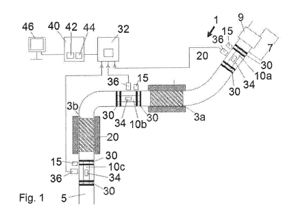
In fig. 1 an arrangement 1 for forming a freeze plug 3a in a tubing 5
according to an embodiment of
the invention is disclosed. The tubing 5 is for example a pipeline used for
conducting oil and gas.
A section 7 of the tubing 5 is to be repaired. In fig. 1, for illustration
purposes the repair depicted in
this case relates to replacement of a damaged valve 9 on the tubing with a new
valve. Before initi-
ating repair operation, the section 7 of the tubing 5 needs to be isolated
from the rest of the tubing
5. In fig. 1, the section 7 of the tubing is isolated from the tubing by means
of forming the freeze
plug 3a and a further freeze plug 3b.
The arrangement 1 comprises an elongated first displacement element 10a, an
elongated second
displacement element 10b and an elongated third displacement element 10c. The
displacement
elements 10a, 10b, 10c are adapted to be displaced within the tubing 5 with a
medium between
them. The medium is adapted to be frozen into the freeze plug 3a and the
further freeze plug 3b.
The medium is preferably water. However, another medium, such as oil, may also
be solidified to
form the freeze plug.
The displacement elements 10a, 10b, 10c are often denoted "pipeline pigs" or
"pipeline scrapers"
and are used in tubing operations. The displacement elements 10a, 10b, 10c are
displaced within
the tubing 5 by means of a flow of the medium through the tubing 5.
The arrangement 1 further comprises detection devices 15 for detecting the
displacement elements
10a, 10b, 10c within the tubing 5. The detection devices 15 are positioned at
the tubing 5 on de-
sired locations for the displacement elements 10a, 10b, 10c within the tubing
5. The detection de-
vices 15 comprise for example a sensor that detects the displacement elements
10a, 10b, 10c on
basis of magnetic field, radio-transmission, ultra sound, et cetera.
When the displacement elements 10a, 10b, 10c have been positioned in their
desired locations in
the tubing 5, a respective freeze element 20 is arranged at the location
between the first and the
second displacement elements 10a, 10b for forming the freeze plug 3a, and
between the second
and the third displacement elements 10b, 10c for forming a further freeze plug
3b. The freeze ele-
ment 20 comprises a chamber adapted to receive a cooling medium, such as
liquid nitrogen, car-
bon dioxide, et cetera, for solidifying the medium between the displacement
elements 10a, 10b,
10c.
Each of the displacement elements 10a, 10b, 10c comprises a respective sensor
arrangement 30
at their end portions for detecting pressure and a temperature. The
arrangement 1 further compris-
es a measuring unit 32 adapted to receive information from the sensor
arrangements 30 and de-
termining the pressure and the temperature of the respective end portion of
the displacement ele-
ments 10a, 10b, 10c.
5
CA 02990054 2017-12-18
WO 2017/196184
PCT/N02017/050116
The information from the sensor arrangements 30 is transmitted through the
tubing 5 by means of
radio communication or other wireless means of communication. The displacement
elements 10a,
10b, 10c comprise a respective transmitter 34 for transmitting information to
a respective receiver
36 at the outside of the tubing 5. The measuring unit 32 is connected to the
receiver 36 and is
adapted to receive pressure and temperature information from the sensor
arrangements 30.
The arrangement 1 further comprises monitoring unit 40 for collecting the
measurements of the
sensor arrangements 30 and determining if a sufficient freeze plug 3a and
further freeze plug 3b
have been formed on basis of the measurements. The monitoring unit 40
comprises for example a
logic unit 42, such as a CPU, and means for storing data 44, such as a hard
disc drive. Preferably,
the arrangement also comprises a display unit 46 for displaying the pressure
and the temperature,
and the determination on the quality of the freeze plug 3a and further freeze
plug 3b.
The determinations on the quality of the freeze plug 3a and further freeze
plug 3b are made on
basis of difference between the measurements on different ends of the freeze
plug 3a and the fur-
ther freeze plug 3b. In particular, the determination is based on if the
difference between meas-
urements is below a threshold value.
In fig. 2, an example of the first displacement element 10a of the arrangement
1 in fig. 1 is dis-
closed in further details. Preferably, the second and third displacement
element 10b, 10c are pro-
vided with the corresponding features. The first displacement element 10a is
arranged within the
tubing 5.
The first displacement element 10a comprises an elongated form comprising two
opposite end
portions. In the disclosed example, one of the end portions is facing the
freeze plug 3a and the
other end portion is facing the section 7 of the tubing 5 to be repaired.
The first displacement element 10a comprises a respective contact flange 50 at
the two end por-
tions. The contact flange 50 has the function of providing a contact between
the first displacement
element 10a and an inner envelope surface of the tubing 5. The contact flange
50 of the first dis-
placement element 10a enables the medium to essentially be maintained between
two adjacent
displacement elements 10a, 10b, 10c during the duration of freezing the medium
to the freeze plug
3a or the further freeze plug 3b.
The first displacement element 10a comprises two sensor arrangements 30
arranged in respective
end portions. In the disclosed embodiment, the sensor arrangements 30 are
contained within the
displacement element 10a. The sensor arrangements 30 comprise a pressure
sensor element 52
and a temperature sensor element 54. The sensor elements 52, 54 are connected
to the transmit-
ter 34 that is adapted to transmit information on the pressure and temperature
measurements to
the receiver 36 outside the tubing 5.
In fig. 3 a flowchart of a method for forming a freeze plug 3a in a tubing 5
according to an embodi-
6
CA 02990054 2017-12-18
WO 2017/196184 PCT/N02017/050116
ment of the invention is disclosed.
In a step 110, the method comprises displacing the first and the second
displacement elements
10a, 10b within the tubing 5 with a medium between them. The displacement is
done by means of
a flow of the medium. The displacement comprises first arranging the first
displacement element
10a in a launcher and introducing the first displacement element in the
tubing. After the first dis-
placement element 10a has been displaced a certain length within the tubing 5,
the second dis-
placement element 10b is arranged in the launcher and introduced in to the
tubing 5.
In a step 120, the method comprises positioning the first and the second
displacement elements
10a, 10b at respective parts of the tubing in between which the freeze plug 3a
is to be formed.
Preferably, at least one of the first and second displacement elements 10a,
10b are detected by
means of one or more detection devices 15 arranged at the outside of the
tubing 5.
In a step 130, the method comprises freezing the tubing 5 between the first
and the second dis-
placement element 10a, 10b. Thereby freeze plug 3 is formed. The tubing is
preferably frozen by
means of arranging a freeze element 20 at the outside of the tubing 5.
In a step 140, the method comprises measuring the pressure and/or the
temperature on respective
end portions of the first and second displacement elements 10a, 10b, which end
portions facing the
medium between them.
In a step 150, the method comprises determining if a freeze plug 3a of
sufficient quality has been
formed on basis of a difference in at least one of the pressure and the
temperature between the
displacement elements 10a, 10b. Preferably, the determination is based on if
the difference be-
tween the pressure and/or the temperature is less than a threshold value.
In case when the further freeze plug 3b is formed between the second and third
displacement ele-
ments 10b, 10c, the quality of the further freeze plug 3b can determined in a
corresponding manner
to the determination of the freeze plug 3a.
It should be noted that the above-mentioned embodiments illustrate rather than
limit the invention,
and that those skilled in the art will be able to design many alternative
embodiments without depart-
ing from the scope of the appended claims. In the claims, any reference signs
placed between
parentheses shall not be construed as limiting the claim. Use of the verb
"comprise" and its conju-
gations does not exclude the presence of elements or steps other than those
stated in a claim. The
article "a" or "an" preceding an element does not exclude the presence of a
plurality of such ele-
ments. The mere fact that certain measures are recited in mutually different
dependent claims does
not indicate that a combination of these measures cannot be used to advantage.
7