Note: Descriptions are shown in the official language in which they were submitted.
CA 02990059 2017-12-18
The Swedish Patent Office
PCT International Application
PCT/SE2016/050628
21-04-2017
TITLE
Large Lightweight Coffin and Method for its Manufacture
TECHNICAL FIELD
Generally, embodiments herein relate to large lightweight coffins, and to
methods of making such molded containers.
BACKGROUND
Pulp molding is known in the art for producing small packages such as
egg cartons, disposable food dishes, box inserts and other protective
packing materials etc.
3.0 RELATED ART
US 6 245 199 describes a method of pulp molding trays where the
starting material is a suspension containing cellulose fibers. The male
mold half is dipped in a bath of the suspension, and the mold halves are
then pressed together under heat and pressure.
SE 529 897 C2 describes the pulp molding of a tray where a dewatering
receptacle is used to shape a tray of pulp which is then transferred to a
compression tool where the tray is subjected to pressure and heat. It
involves a transfer step and is not readily usable for large containers.
Large containers with smooth surfaces and strong, lightweight structure
have been very difficult to pulp mold. And a complex of difficult to solve
problems have prevented widespread use of pulp molding to produce
lightweight coffins.
EP 0466653, for example, describes a coffin made of molded pulp
without any reinforcing spacer lining. Upper and lower coffin halves are
AMENDED SHEET
CA 02990059 2017-12-18
PCT/SE2016/050628
2 21-04-2017
pulp molded with integral ribs 44, 46 for reinforcement. These prevent a
finished smooth surface and do not permit forming into a classic
attractive coffin shape, with gently curved smooth walls.
US 4 162 935 also describes a coffin made of dewatered paper pulp. The
mold also provides integral ribs 20, for reinforcement, which prevent
having a finished smooth surface and a classic coffin shape.
W006016072 describes boards or panels consisting of honeycomb layers
with paper sheet faces and possibly polyurethane coating. One possible
mentioned use of this honeycomb board is for constructing a lightweight
3.0 and inexpensive coffin.
GB-2448592 describes a coffin made of sandwich honeycomb
paperboard panels, which can be covered with veneer or other material
to give the appearance of wood.
However, none of the related art discloses or hints at how to achieve the
solutions provided by embodiments herein.
OBJECT OF THE INVENTION
Embodiments herein intends to solve a complex of difficult-to-reconcile
interrelated problems still present in the designs of the prior art:
It has been very difficult to use existing pulp molding methods to
produce very large objects. This is due partially to the problem of thermal
expansion and contraction of the two metal mold halves used in the
compression of the pulp in the press. If the dimensions of the mold
halves change, due to unavoidably becoming cooler and hotter during the
compression process, the strength of the container will be compromised
and the surface will not be smooth and even. This is not a problem if the
surface quality and the strength of the finished object is of no great
AMENDED SHEET
CA 02990059 2017-12-18
PCT/SE2016/050628
3 21-04-2017
importance, such as for packaging materials or disposable dishes, but
where the strength and surface finish of the finished molded product is of
great importance then this is a problem. In general it is difficult to
achieve uniformity of strength and surface in pulp molded products,
s particularly in such products which are thin.
It is now possible to make a large volume lightweight shell of molded
pulp with improved strength and smoothness using the mold halves and
apparatus described and claimed in our co-pending patent application
No. 1550864-1 entitled Pulp Molding Apparatus and Molds for Use
1.0 Therein
and with the lightweight 3-D shaped material described in our co-
pending patent application No. 1550866-6 entitled Large Lightweight
Molded Material and Method for its Manufacture.
is Providing a coffin, which is lightweight, very strong, with smooth and
even outer surface and above all is easy and inexpensive to manufacture
has hitherto proved very difficult.
SUMMARY
This entire complex of problems listed above finds its solution in
20 embodiments herein as defined in the appended main patent claims.
According to embodiments, a large lightweight molded coffin comprising
an outer shell of molded pulp and a core material used as a reinforcing
spacer material conforming to and adhering to the interior of the shell,
and an inner shell made of molded pulp or a flexible paper based
25 material adhering to the core spacer material is provided.
AMENDED SHEET
CA 02990059 2017-12-18
PCT/SE2016/050628
4 21-04-2017
In embodiments, the spacer material may be a paper based honeycomb
sheet of hexagonal cells.
In embodiments, the core spacer material may be made of a spacer
structure of molded pulp.
In embodiments, the reinforcing spacer material may be made of Re-
board .
In embodiments, the Re-board spacer material may have only a single
interior cover sheet.
In embodiments, the reinforcing spacer material may comprise hollow
cells separated by walls substantially perpendicular to the shell.
In embodiments, the outer shell may be molded of pulp with a fire-
retardant additive.
In embodiments, a coffin cover may also comprise an outer shell of
molded pulp and a reinforcing spacer material.
In another aspect, a method of producing a molded coffin comprising
a. Pressing slurried pulp between a first male mold half covered with
elastomeric material and a second female mold half, and drying the
material at elevated temperature under pressure, to form the molded
pulp shell,
AMENDED SHEET
CA 02990059 2017-12-18
PCT/SE2016/050628
21-04-2017
b. providing a core spacer structure and gluing the reinforcing spacer
structure to the interior of the molded pulp shell.
c. provide an inner shell made of molded pulp or another flexible paper
based material and gluing it to the core spacer structure is provided.
5
In embodiments, methods may comprise admixing a measured amount
of fire retardant to the slurried pulp and/or spraying a fire retardant to
the surface of the shells.
1.0 In embodiments, methods may comprise admixing a measured amount
of dry- and wet strength additive to the slurried pulp.
In embodiments, methods may comprise admixing a measured amount
of hydrophobizing additive in the slurried pulp.
In embodiments, methods may comprise surface treating the outer layer
of the coffin material with a hydrophobizing coating by spray or coating.
In embodiments, methods may comprise spraying an adhesive on the
inner side of the shell in order to glue the spacer material to the shell.
In another aspect, a large lightweight coffin comprising a curved outer
shell of molded pulp and a flexible core material used as a reinforcing
flexible spacer conforming to and adhering to the interior of the shell,
and an inner shell made of molded pulp or a flexible paper based
material adhering to the core spacer material is provided.
AMENDED SHEET
CA 02990059 2017-12-18
PCT/SE2016/050628
6 21-04-2017
In embodiments, the reinforcing flexible spacer may be a paper based
honeycomb sheet of hexagonal cells,
In embodiments, the reinforcing flexible spacer may be a corrugated core
structure.
In embodiments, the reinforcing flexible spacer may be made of a spacer
structure of molded pulp.
In embodiments, the reinforcing flexible spacer may be made of Re-
board@ . fluted paperboard.
In embodiments, the Re-board spacer may have only a single interior
lo cover sheet.
In embodiments, the reinforcing flexible spacer may comprise hollow
cells separated by walls substantially perpendicular to the shell.
In embodiments, the outer shell may be molded of pulp with a fire-
retardant additive.
In embodiments, a coffin cover may also comprise an outer shell of
molded pulp and a reinforcing spacer material.
According to another aspect, a method of producing a coffin comprising
a. Pressing slurried pulp between a first male metal mold half spray
coated or cast with elastomeric material and a second female metal mold
half, and drying the pulp slurry at elevated temperature under pressure,
to form the curved molded pulp shell,
b. providing a flexible spacer structure and gluing it as the reinforcing
flexible spacer to the interior of the curved molded pulp shell.
c. providing an inner shell made of molded pulp or another flexible paper
based material and gluing it to the reinforcing flexible spacer is provided.
AMENDED SHEET
CA 02990059 2017-12-18
PCT/SE2016/050628
7 21-04-2017
In embodiments, methods may comprise admixing a measured amount
of fire retardant to the slurried pulp and/or spraying a fire retardant to
the surface of the shells.
In embodiments, methods may comprise admixing a measured amount
of dry- and wet strength additive to the slurried pulp.
In embodiments, methods may comprise admixing a measured amount
of hydrophobizing additive in the slurried pulp.
In embodiments, methods may comprise treating the outer layer of the
coffin material with a hydrophobizing coating by spray or coating.
lo In embodiments, methods may comprise spraying an adhesive on the
inner side of the shell in order to glue the flexible reinforcing spacer to
the shell.
BRIEF DESCRIPTION OF DRAWINGS
Embodiments herein will now be described in more detail with reference
to the appended drawings, wherein:
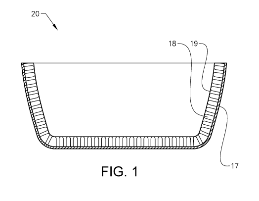
Fig. 1 shows a cross sectional view of a lower portion of a coffin according
to embodiments herein.
Fig. 2a shows a perspective view of the lower portion of the coffin shown
in Fig. land Fig. 2b shows a perspective view of the coffin provided with
a lid.
Fig. 3 shows schematically the pair of mold halves used in a method
which can be used to manufacture the shells for a coffin according to
embodiments herein.
AMENDED SHEET
CA 02990059 2017-12-18
PCT/SE2016/050628
21-04-2017
DETAILED DESCRIPTION
The lower receptacle portion of a large lightweight molded coffin
according to embodiments herein is shown in cross section in Fig. 1 and
s in perspective in Fig. 2(a). The complete coffin with a lid made in a
similar manner of molded pulp is shown in Fig. 2b.
The lightweight material used in the coffin is built up as a sandwich
construction by three different parts comprising:
i) An outer shell 17 made of 3-D shaped molded pulp. [This is the
surface of the material and will have a smooth and even surface
and make possible complex 3-D shaped designs , produced , for
example, by using the novel method for producing large molded
pulp objects described in our co-pending Patent Application No.
1550864-1. entitled Pulp Molding Apparatus and Molds for Use
Therein
A core 18 composed of a flexible spacer structure that may have,
but is not limited to having, a core of Re-board a paper
honeycomb structure, a molded core structure (as described in
e.g. International Patent Application No W02010138066 Al), or
the corrugated core structure made by fluting used in corrugated
boards.
ii) iii) An inner shell 19 made of molded pulp or a flexible paper
based material such as a linerboard or paperboard.
AMENDED SHEET
CA 02990059 2017-12-18
PCT/SE2016/050628
9 21-04-2017
By using a sandwich construction as described above, complex 3D-
shaped designed coffins can be made while at the same time obtain a
high strength material.
In one of embodiments herein, the outer shell 17 of the coffin is made of
molded pulp and is lined in the embodiment shown with Re-boardowith
only a single linerboard, on its exposed interior surface 19. The Re-
boardethen composes both the core structure ii) above) and the inner
shell (iii) above). As one of the linerboards has been removed from a
normal Re-boardomaterial, the Re-board 18 can be bent, without
1.0 breaking, to conform to the inside of the molded pulp shell 17 before
being glued to the shell, which will then replace the missing linerboard of
the reinforcing Re-board spacer structure.
It is of course also possible to use other core materials used as spacers to
line the outer molded pulp shell of the coffin that are able to conform to
the interior curvature of the molded pulp shell. A honeycomb structure,
having walls extending perpendicular to the surface of the shell is also
one possible spacer material, as well as the corrugated core used in
corrugated board, or pulp molded spacer material as described above,
thereafter covered with another inner shell made of molded pulp of a
paper based material in order to create a strong light weight material.
A number of special functional characteristics apply to coffins, in
particular if they are intended for cremation. The specifications of a
normal coffin are:
i) Have enough mechanical strength for carry a body weight of 120
kg.
ii) Have a dimensional stability and wet strength that enables
storage in a freezer.
AMENDED SHEET
CA 02990059 2017-12-18
PCT/SE2016/050628
21-04-2017
iii) Have water repellent properties to withstand rainy weather.
iv) If used in cremation, withstand the heat in a cremation oven (ca
900 C) for at least 15 sec. without catching fire.
A cardboard/reboard coffin can be expected to have exceptionally fast
s combustion. For safety of the crematorium workers and for optimum
cremation of the body, according to one embodiment of embodiments
herein, a measured amount of fire retardant is mixed into the slurry for
making the molded pulp shell and/or sprayed on the surface of the
molded shell(s) and the core spacer material. In order to make the
in molded shells stiff enough, dry strength additives are added to the pulp
and in order to have enough wet strength enabling storage in a freezer,
wet strength additives are added to the pulp in sufficient amount. To
achieve enough water repellent properties on the outer shell, a
hydrophobization additive is added to the pulp slurry. The
hydrophobization may be even more increased by adding a
hydrophobizing surface coating by using spray or a coating machine.
There may also be adhesives sprayed on the inner surface(s) of the
shell(s), which will make the core spacer material adhere to the shell(s)
and become securely glued thereto.
The molded 3-D shaped material 17 has an even and smooth surface and
good mechanical properties. The density of the molded materials needs
to be at least 100 kg / m3 in order to obtain proper stiffness but may be
even higher depending on the pressure used during the molding process.
The molded material may be made of pulp from various fibers such as
virgin wood fibers (e.g. chemothermo-mechanical pulp, chemical pulp or
mechanical pulp), recycled wood fibers, textile fibers made of viscose,
cotton or other cellulosic fibers, but may also be made of pulp comprising
fibers mixed with thermoplastic fibers such as polylactic acid (as
AMENDED SHEET
CA 02990059 2017-12-18
PCT/SE2016/050628
11 21-04-2017
described in e.g. patent no EP2171154 Al) in order to create composite
materials. Fig. 2a shows the lower receptacle portion 17 of a coffin
according to embodiments herein, provided with an inner spacer
structure and an inner shell 19. Fig. 2b shows a complete closed coffin
according to embodiments herein with the lid 21 in place on the bottom
portion of the coffin 20.
Fig. 3 shows in longitudinal cutaway view a pair of mold halves used for
manufacturing shells 17 for the reinforced coffins of embodiments
herein. The male mold half 5 is made of hollow aluminum and is coated
with an elastomer 6 which is ca 30 mm thick. This elastomer is
preferably sprayed onto the aluminum mold half. It is also possible to
cast the elastomer onto the aluminum mold half. Atypical elastomer 6
should be hydrophobic but not be subject to hydrolysis. An advantageous
hardness, particularly for a sprayed-on elastomer is 70 A-Shore, to
provide optimal elastic properties. 5mm diameter through-holes spaced
15 mm from each other cover the elastomer layer and connect to
through-holes 8 in the aluminum body of the male mold half 5. Within
the male mold half there is generated a vacuum of 0.5-0.9 bar. On top of
the elastomer layer there is a wire mesh. In this case it is a 100 mesh (i.e.
100 threads per inch) and is approximately 1 mm thick. The wire mesh
can also be laid in multiple layers which will further contribute to
distributing the vacuum forces more evenly. The female mold-half 3 is
made of aluminum and has in this example a weight of 70 0 kg. It is
heated to ca. 200 degrees C., for example by means of heating rods
embedded in the material of the female mold-half 3. This is the most
energy effective method of heating the female mold-half. Its inner surface
will create the outer surface of the product. The two mold halves can be
made of porous aluminum to increase strength over sintered material
and to increase heat conductivity.
AMENDED SHEET
CA 02990059 2017-12-18
PCT/SE2016/050628
12 21-04-2017
The male mold-half 5 after being dipped in the slurry bath dewaters the
slurry through vacuum to approximately 20% dryness (80% water) and
the male mold-half 5 is then pressed into the female mold-half 3 down to
a gap of ca. 1 mm between the two mold halves. It can vary for this
particular product between ca. 0.8 and ca. 1.2 mm without detrimental
effects. The material is then dried under pressure at an elevated
temperature (>100 degrees, preferably 150 degrees). Due to absorbing
coolness from the male mold-half 3 (temp of ca. 250C), the hot aluminum
female mold-half 5 (initially ca. 200 C) will in turn drop ca. 13 degrees C
3.0 during the compression process. This temperature change causes the
female mold-half to shrink over its length approximately 7-8 mm with
corresponding contractions in its width (2.5 mm) and height (1.5 mm).
This is compensated for by the elastomer layer 6. The temperatures in
both the female and male mold-halves will vary up and down during the
compression process thus repeatedly changing slightly the dimensions on
the molds. In conventional pulp molding processes, these dimensional
variations would cause stresses and unevenness in the finished product,
possibly even ruptures. In this particular exemplary product, without an
elastomer layer, the temperature of the female mold-half must be rather
precise, i.e. in this example between ca. 195. and 2040C This precision is
difficult to achieve and maintain in an industrial process of this type.
These problems have been experienced even in the manufacture of
relatively small pulp molded products, and require precise adjustment of
the temperature to avoid them. Most pulp molded products, such as egg
cartons, are several millimeters thick and are thus more porous and it
makes no difference whether such products have a rough surface. A
product with a rough surface cannot be used in many applications. For a
large product, the problems of dimensional heat expansion/contraction
will be greatly increased. These problems have hitherto made it
AMENDED SHEET
CA 02990059 2017-12-18
PCT/SE2016/050628
13 21-04-2017
impossible to manufacture large pulp molded products with reasonable
reject rates and with a smooth surface.
Embodiments herein was developed inter alia in order to produce shells
for coffins with very few rejects and no necessity of precisely monitoring
s and continually adjusting the temperatures of the two mold-halves. Since
the elastomer is used to absorb much of the dimensional variation of the
male and female mold-halves, they can be made much lighter and
thinner than otherwise since they will not require a large mass to prevent
temperature variations. For instance, in this example the female mold-
half weighs ca. 750 kg. If it had to maintain a more constant temperature
it might have to have a mass of several tons, requiring more energy to
heat such a large mass and maintain the heat.
A coffin has in general curved sides, something which is expensive to
produce in plywood or with wood planks. According to embodiments
is herein it is possible to produce shells of ca. 1-2 mm in thickness,
which
provides the maximum stiffness. Thicknesses greater or less than this
thickness (1-2 mm) provide less stiffness
These problems are solved by coating the surface of the male mold-half
with an elastomeric material, onto which the wire mesh or meshes is/ are
then applied. This elastomeric material continually compensates for the
varying dimensions of the two mold-halves during the
compression/heating process.
It is also advantageous for molding the shell to mount the stationary
mold half (in this case the female mold half) to be slightly horizontally
moveable (+- 25 mm) to make sure that any heating expansion will not
prevent a correct horizontal alignment between the male and female
mold halves during the pressing operation.
AMENDED SHEET
CA 02990059 2017-12-18
PCT/SE2016/050628
14 21-04-2017
As can be seen in Fig. 3, the male mold half is provided with troughs 14
and large holes 8 beneath the elastomer layer in order to prevent any
reduction of the vacuum which holds the pulp slurry and dewaters it on
the surface of the wire mesh.
Other embodiments herein further describe a method to produce the
molded lightweight coffin described above. The steps to produce the
coffin comprises:
i) Provide a 3-D shaped molded material according to the design
of the specific coffin by using the apparatus described above
3.0 with or without addition of functional additives which will be
used as outer shell 17 of the coffin
ii) Provide a spacer material used as core 18 in the coffin material,
and glue said core spacer material to the outer 3-D shaped
molded shell
iii) Provide an inner shell 19 made of a 3-D shaped molded material
or a flexible paper based material which will adhere to the
spacer material 18.
AMENDED SHEET