Note: Descriptions are shown in the official language in which they were submitted.
CA 02990180 2017-12-19
WO 2016/205810
PCT/US2016/038407
IMPROVED AGRICULTURAL MAT AND ASSOCIATED SYSTEMS AND METHODS
CROSS-REFERENCE TO RELATED APPLICATION(S)
[001] This application claims priority to U.S. Provisional Application No.
62/182,246
filed June 19, 2015 and entitled "Improved Agricultural Mat And Associated
Systems And
Methods," which is hereby incorporated by reference in its entirety under 35
U.S.C. 119(e).
TECHNICAL FIELD
[002] The disclosure relates to a device, systems and methods relating to a
mat or cover
for use in agricultural applications. More specifically, the disclosed
embodiments relate to an
improved mat or slat cover for use with livestock in conjunction with slats.
In exemplary
embodiments, the devices, systems and methods relate to an interlocking mat or
slat cover for
placement above concrete slats.
BACKGROUND
[003] The disclosure relates to mats for placement on livestock slats. In
the livestock
industry, slats, frequently made of concrete, are placed in livestock
buildings, and more
specifically are placed in indoor livestock pens and containment areas.
Typically, the slats have
gaps defined therein that allow for feces and other waste liquids (such as
from animal watering
systems, etc.) to pass through to an area beneath the slats, thereby reducing
or eliminating the
collection or accumulation of such feces and waste liquids in the pen. This
helps to reduce
contact of the livestock with such feces and waste liquids, thereby reducing
illness and injury
resulting from the presence of such liquids. The use of slats makes it
possible to retain livestock
in a building or enclosure for an extended period of time, including, for
example, during the
winter months. And keeping livestock in an indoor environment during cold
weather can
enhance the efficient growth of the livestock, as the livestock will gain
weight faster in the
warmer indoor environment.
[004] These slats, being made of concrete or other solid, rigid material,
can cause
additional strain on the joints and feet of the livestock. Previous attempts
to address this strain
have involved the placement of mats over the slats. however, these prior art
slats have a tendency
CA 02990180 2017-12-19
WO 2016/205810
PCT/US2016/038407
2
to move on the slats, which can cause them to be displaced, and to accumulate
bacteria and other
unwanted materials between the mats and the slats. Further, prior art slats
have typically utilized
thin, hard coverings of less than an inch with a durometer of more than 70,
and are frequently
held in place by bolts or other metal fasteners, thereby contributing to the
development of joint
problems in the animals, and diseases when the mats are pulled up and exposed
to accumulated
bacteria. Further, certain prior art covers also require the use of a
sledgehammer to install. The
various embodiments of the slat cover described herein, including the
associated systems and
methods, address the deficiencies of the prior art.
[005] There is a need in the art for improved devices, systems and methods
for covering
livestock slats.
BRIEF SUMMARY
[006] Discussed herein are various embodiments of an improved slat cover or
mat, as
well as associated systems and methods for its use. For brevity, these
embodiments may be
described as a "slat cover", or in relation to a single modality, though that
is not intended to limit
the scope of the disclosure in any way.
[007] In Example 1, a livestock slat cover comprises a substantially
rectangular mat
comprising first and second sides, a plurality of edges and at least one
opening; at least one
center lug disposed on the second side adjacent to the opening on the second
side of the mat; and
at least one edge lug disposed at one edge of the mat.
[008] Example 2 relates to the slat cover according to Example 1, wherein
the edge lug
further comprises a first and second end, wherein the first end is fixedly
attached to the mat and
the second end further comprises a protrusion.
[009] Example 3 relates to the slat cover according to Example 1, wherein
the mat is
comprised of rubber.
[010] Example 4 relates to the slat cover of Example 3, wherein the mat is
at least one
inch thick.
[011] Example 5 relates to the slat cover of Example 1, further comprising
a plurality of
buttons disposed on the first side of the mat.
[012] Example 6 relates to the slat cover of Example 5, wherein the
plurality of buttons
further comprise lower and upper buttons.
CA 02990180 2017-12-19
WO 2016/205810
PCT/US2016/038407
3
[013] Example 7 relates to the slat cover of Example 2, further comprising
at least one
edge gap.
[014] Example 8 relates to the slat cover of Example 7, wherein the edge
lug is
configured such that the gap and protrusion allow multiple covers to be
interlocked with one
another between slats.
[015] In one Example, A slat cover for use with livestock, including a
substantially
planar mat including first and second sides, a plurality of edges and at least
one opening, and at
least one edge lug, where the at least one edge lug is configured to interlock
with an adjacent
mat. Implementations may include one or more of the following features. The
slat cover where
the at least one edge lug includes a first and second end, where the first end
is fixedly attached to
the mat and the second end including a protrusion. The slat cover further
including at least one
center lug disposed on the second side adjacent to the at least one opening,
and The slat cover
where the mat is included of a single piece of rubber. The slat cover where
the rubber has a type
A durometer of between 60 and 70. The slat cover where the mat is included of
rubber. The slat
cover including a plurality of buttons disposed on the first side of the mat.
The slat cover where
the plurality of buttons further include lower and upper buttons. The slat
cover further including
at least one edge gap. The slat cover where the edge lug is configured such
that the edge gap and
protrusion allow multiple covers to be interlocked with one another between
slats. The single-
piece slat cover further including at least one center lug disposed to the at
least one opening. The
single-piece slat cover where the at least one edge lug includes an angled
protrusion. The single-
piece slat cover where the protrusion is angled to contour around a non-
vertical portion of the
underside of the slat. The single-piece slat cover where the at least one edge
lug is configured to
interlock with a second mat edge lug. The single-piece slat cover further
including a lip disposed
around the opening. The system where the first and second planar mats further
include an edge
gap. The system where the first and second edge lugs are configured to
interlock by sliding
through the edge gap. The system where the first and second edge lugs each
include an angled
protrusion. The system further including at least one center lug.
[016] In one Example, A single-piece slat cover to be disposed over a slat,
including a
substantially planar mat, at least one opening, and at least one edge lug.
Implementations may
include one or more of the following features The single-piece slat cover
further including at
least one center lug disposed to the at least one opening. The single-piece
slat cover where the at
CA 02990180 2017-12-19
WO 2016/205810
PCT/US2016/038407
4
least one edge lug includes an angled protrusion. The single-piece slat cover
where the
protrusion is angled to contour around a non-vertical portion of the underside
of the slat. The
single-piece slat cover where the at least one edge lug is configured to
interlock with a second
mat edge lug. The single-piece slat cover further including a lip disposed
around the opening.
The system where the first and second planar mats further include an edge gap.
The system
where the first and second edge lugs are configured to interlock by sliding
through the edge gap.
The system where the first and second edge lugs each include an angled
protrusion. The system
further including at least one center lug.
[017] In one Example, An interlocking slat cover system, including a first
planar mat
including at least one first mat edge lug, and a second planar mat including
at least one second
mat edge lug, where the first planar mat and second planar mat are configured
to be interlocked
in a slat opening to secure the first mat and second mat in place.
Implementations may include
one or more of the following features. The system where the first and second
planar mats further
include an edge gap. The system where the first and second edge lugs are
configured to interlock
by sliding through the edge gap. The system where the first and second edge
lugs each include an
angled protrusion. The system further including at least one center lug.
[018] While multiple embodiments are disclosed, still other embodiments of
the
disclosure will become apparent to those skilled in the art from the following
detailed
description, which shows and describes illustrative embodiments of the
disclosed apparatus,
systems and methods. As will be realized, the disclosed apparatus, systems and
methods are
capable of modifications in various obvious aspects, all without departing
from the spirit and
scope of the disclosure. Accordingly, the drawings and detailed description
are to be regarded as
illustrative in nature and not restrictive.
BRIEF DESCRIPTION OF THE DRAWINGS
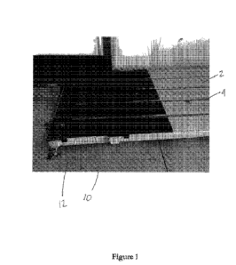
[019] FIG. 1 is a perspective view of a partial slat cover over a slat,
according to an
exemplary embodiment.
[020] FIG. 2 is another perspective view of a slat cover, according to an
exemplary
embodiment.
[021] FIG. 3A is a top view of first and second slat covers, according to
an exemplary
embodiment.
CA 02990180 2017-12-19
WO 2016/205810
PCT/US2016/038407
[022] FIG. 3B is a bottom view of the first and second slat covers of FIG.
3A.
[023] FIG. 4 is a perspective underside view of a slat cover, showing the
edge and
center lugs, according to an exemplary embodiment.
[024] FIG. 5A is a front view of a center lug, according to an exemplary
embodiment.
[025] FIG. 5B is a top view of a center lug, according to an exemplary
embodiment.
[026] FIG. 5C is a top view of a center lug, according to another exemplary
embodiment.
[027] FIG. 5D is a top view of an edge lug, according to yet another
exemplary
embodiment.
[028] FIG. 5E is a front view of an edge lug, according to an exemplary
embodiment.
[029] FIG. 5F is a top view of an edge lug, according to an exemplary
embodiment.
[030] FIG. 5G is a top view of an edge lug, according to another exemplary
embodiment.
[031] FIG. 5H is a top view of an edge lug, according to yet another
exemplary
embodiment.
[032] FIG. 6A is a end-long view of the placement of a second slat cover
adjacent to a
first slat cover, according to an exemplary embodiment.
[033] FIG. 6B is a close-up end-long view of the embodiment of FIG. 6A
after
placement.
[034] FIG. 7 is a top view of the placement according to the embodiment of
FIGS. 6A-
B.
[035] FIG. 8A is a detailed top view of the relationship between the edge
lugs initial
during placement, according to an exemplary embodiment.
[036] FIG. 8B is a detailed top view of the relationship between the edge
lugs of
adjacent covers being brought into alignment, according to the embodiment of
FIG. 8A.
[037] FIG. 8C is a detailed top view of the relationship between the edge
lugs of
adjacent covers after being urged into alignment, according to the embodiment
of FIG. 8A.
[038] FIG. 9A is a perspective view of the underside of two slat covers
adjacent to one
another, according to an exemplary embodiment.
[039] FIG. 9B is a perspective view of the underside of two slat covers
adjacent to one
another, according to an alternate embodiment having an opening lip.
CA 02990180 2017-12-19
WO 2016/205810
PCT/US2016/038407
6
[040] FIG. 10 is a further perspective view of a partial slat cover placed
on a slat,
according to an exemplary embodiment.
[041] FIG. 11 depicts a close-up view of the top surface of a slat cover
showing an
embodiment having a plurality of buttons.
DETAILED DESCRIPTION
[042] Livestock, including but not limited to cattle, swine, and sheep, are
frequently
contained in relatively high population environments. In these environments,
the owners of the
livestock must address the animal waste that is generated by these dense
populations. One
system that has been developed is the use of livestock slats, which are
typically formed from
concrete and contain substantially rectangular openings occurring at regular
intervals.
[043] Disclosed herein are various devices, systems and methods relating to
the
covering of livestock slats. In exemplary embodiments, these mats or slat
covers are generally
rectangular and planar, and have a plurality of openings, with center lugs and
edge lugs disposed
on the underside adjacent to the openings and edges, respectively. These mats
or covers are
generally designed to be secured in place over a slat, for instance a concrete
slat, by way of these
lugs. These mats are for use with livestock, and after being secured by the
lugs, these mats or
covers are configured to stay in a stationary position, that is: the mats are
configured to not move
despite the considerable force applied to the mats by the movement of
livestock.
[044] Accordingly, in certain implementations the edge lugs of one mat are
configured
to interlock with the edge lugs of a second mat. That is, the pairs of edge
lugs are disposed
adjacently so that friction prevents the movement of both mats on the
underlying slats. In certain
implementations, the mat has a first side and a second side, with buttons for
improved traction
disposed on the first side. In various implementations, the center and edge
lugs extend from the
second side, these lugs being configured to slide and lock in place when
several mats are used
together. In further embodiments, a plurality of lug gaps are provided such
that two mats can be
interlocked adjacent to one another, as is provided below.
[045] Turning to the drawings in greater detail, a perspective view of a
slat 2 having a
partial interlocking cover 10 according to one embodiment is shown in FIG. 1.
As best shown in
the implementation of FIG. 1, a typical slat 2 has a plurality of openings 4,
and a portion of a
cover 10 having a plurality of corresponding openings 20, 22, and edge lugs
60A, 60B, as will be
CA 02990180 2017-12-19
WO 2016/205810
PCT/US2016/038407
7
discussed herein. It is understood that the livestock are able to stand on
these slats and generate
waste which then falls or otherwise travels through the openings 4 and into a
collection area
below (not shown) for removal or disposal.
[046] Exemplary embodiments of the presently-disclosed interlocking slat
cover 10
reduce movement, prevent injury and disease in livestock, and are easy to
install, as they require
no additional hardware to be installed or held in place. In exemplary
embodiments, a modular
system of covers is provided, such that the individual covers can be placed
sequentially and
secured into place relative to one another using an adjacent lug
configuration. The provided
adjacent lug configuration provides for ease of installation and greater slat
cover stability against
being displaced and the other problems with the prior art.
[047] In certain implementations, the mat is a rubber mat. In certain
implementations,
the rubber is a natural and synthetic blend. Other materials may be used. In
exemplary
embodiments, the mat is more than an inch thick, such as 1.05". In certain
implementations, the
mat has a type A durometer between 50-80, or between 60-70. In further
implementations, a
durometer of 62-68 is utilized. In yet further embodiments, rubber of a
durometer between 64-
66 is used, though it is understood that other rubbers and materials can be
used. These
implementations are softer than typical prior art covers, and therefore can
further reduce the
stress and wear on livestock. It is further understood that in certain
implementations each mat or
slat cover is formed from a single piece of molded rubber.
[048] FIG. 2 depicts a perspective overview of an exemplary embodiment of
the slat
cover 10. Exemplary embodiments of the slat cover 10 comprise a generally
rectangular, planar
mat 12 having top 14 and bottom 16 sides, and further comprising a plurality
of openings 20, 22
configured to align with the openings in the underlying slat (shown in FIG. 1)
so as to allow for
the passage of waste through the openings 20 in the mat 12 and slat 4. In
exemplary
embodiments, the slat cover 10 has a plurality of protrusions or buttons 30 on
the top side,
discussed in detail in relation to FIG. 8.
[049] In exemplary embodiments, the slat cover 10 is sized such that two
covers are
placed on a single slat. For example, an exemplary slat may be 4'x12', and
each slat cover is
sized at 4' x6' . It is understood that various species of livestock have
specific slat configurations,
and various manufacturers also have different specific slat configurations,
and the cover 10 can
be adapted to address each set of dimensions and opening arrangements.
CA 02990180 2017-12-19
WO 2016/205810
PCT/US2016/038407
8
[050] By way of example, a first slat cover 10A depicted in FIG. 3A is
joined with a
second slat cover 10B (as best shown in FIG. 7) so as to cover the width of an
entire slat. FIG.
3A depicts a top view of the first 10A and second 10B slat covers, while FIG.
3B depicts a
bottom view of the same slat covers 10A, 10B. Other configurations are of
course possible.
[051] As will be apparent to one of skill in the art from the
implementations of FIGS.
3A-B, in certain configurations the first cover 10A and second cover 10B will
be paired and
adapted to the underlying slat, depending on the exact shape of the slat and
its openings (as is
also shown in FIGS. 1 and 10). Accordingly, the various components of the
cover 10 may vary
in size and placement, such as placement and width of the various openings 20,
22 and the width
of the lugs (discussed in relation to FIG. 5A-H).
[052] Exemplary embodiments of the slat cover 10 have various lugs used to
secure the
mats. These can be center lugs 40 and edge lugs 60, which protrude from the
bottom 16 of the
slat cover 10 adjacent to the openings 20, 22, as shown in FIGS. 3B-4. These
lugs are of
substantial thickness to be relatively rigid, that is, when fitted in a slat
opening or between slats,
the lugs are resistant to bending or twisting movement relative to the mat.
Accordingly, the
various lugs 40, 60 protrude in a substantially perpendicular direction from
the bottom 16 of the
mat. The center lugs 40 have a first end 42 which is fixedly attached or
otherwise materially
connected to or integral with the mat 12 and a second end 44 which extends
into the slat opening
(shown in FIGS. 1 and 6A) so as to hold the slat cover 10 in place, as is
shown in detail greater
in relation to FIG. 4.
[053] FIGS. 5A-H depict front and top view schematics of several
implementations of
the center 40 and edge 60 lugs. In certain embodiments, the lugs are made of
rubber or other
material, and, in the case of the center lugs 40, are sized so as to abut
against at least two faces of
the slat opening (shown at 4A and 4B in FIGS. 6A-B).
[054] As is shown in the implementation of FIGS. 5A-D, the center lugs 40
can be a
variety of heights 46, lengths 48 and widths 50, so as to be adapted to fit
within the slat openings,
thereby helping to keep the cover in place. Further, the lugs 40 are adapted
such that they don't
fill the slat opening and thus they allow the waste to pass through the mat
openings 20, 22 and
slat openings 4, as would be apparent to one of skill in the art. In certain
embodiments, the
center lugs 40 have a tapered portion 52A, 52B at the second end 44 for ease
of insertion into the
slat openings 4.
CA 02990180 2017-12-19
WO 2016/205810
PCT/US2016/038407
9
[055] FIG. 5E-H several implementations of the edge lug 60, which has a
generally
rectangular body 61, a first end 62 which is fixedly attached or otherwise
materially connected to
or integral with the underside 16 of the mat 12 and a second end 64 which
extends into the
opening between two slats. The edge lugs 60 have can be a variety of heights
66, lengths 68 and
widths 70. As is shown in FIG. 5E, in these implementations the second end 64
has a protrusion
65, which in certain embodiments is tapered or angled so as to be adapted to
extend beyond the
body 61 and contour around the non-vertical portion 2A of the slat 2 (as is
best shown in FIGS.
6A-B). It is understood that the dimensions of the lugs 40, 60 can be any
known dimensions to
allow for use of the cover embodiments herein with any known livestock slats.
[056] As shown in the implementations of FIGS. 6A-7, the slat cover serves
to be
secured to the slat. As best shown in FIG. 6A, in certain implementations, the
protrusions 65B
of the side lugs 60A prevent the placement of a second cover 12A immediately
adjacent to a first
cover 12B. As shown the implementations of FIGS. 6A-7, when a second mat 12B
is placed
above the desired location - next to the first mat 12A such that the edge lugs
are in alignment -
the edge lugs 60B, 60D, 60F, 60H cannot be inserted directly into the slat
opening 80 from above
because the edge lugs 60A, 60C, 60E, 60G of the first mat 12A cannot fit into
the slat opening
while positioned directly adjacent to the edge lugs 60B, 60D, 60F, 6011 of the
second mat 12B.
That is, because of the width of the protrusions 65A, 65B on each edge lug, a
second edge lug
60A cannot be inserted into a slat opening while the corresponding edge lug
60B on the
previously placed mat is already positioned in the slat opening at the same
location along the
length of the slat opening.
[057] In exemplary embodiments as best shown in FIG. 7, the edge lugs 60A,
60C, 60E,
60G extend from the edge of a first mat 12A while edge lugs 60B, 60D, 60F, 60H
extend from
the edge of a second mat 12B that is intended to be positioned adjacent to the
first mat 12A.
Note that the edge lugs 60A, 60C, 60E, 60G of the first mat 12A correspond to
the edge lugs
60B, 60D, 60F, 6011 of the second mat 12B such that when they are positioned
correctly next to
each other on a slat, the edge lugs 60A, 60C, 60E, 60G will be positioned
against edge lugs 60B,
60D, 60F, 60H, respectively.
[058] In the implementation of FIG. 7, there are gaps 80A, 80C, 80E between
the edge
lugs 60A, 60C, 60E, 600 of the first mat 12A and corresponding gaps 80B, 80D,
80F between
the edge lugs 60B, 60D, 60F, 60H of the second mat 12B. When the mats 12A, 12B
are brought
CA 02990180 2017-12-19
WO 2016/205810
PCT/US2016/038407
into the final adjacent configuration, the pairs of these gaps 80A, 80B are
also positioned
adjacent to one another so as to form an opening corresponding to a typical
slat opening 20 or
22. Other configurations are possible.
[059] As is shown in FIGS. 7A-8C, in exemplary embodiments, when a first
10A and
second 10B slat cover are placed on adjacent slats, it is typically done
sequentially, with first one
mat ( such as the second mat 12B) being placed on the slat at its desired
location and then
another mat (such as the first mat 12A) being placed adjacent to the second
mat 12B.
[060] As such, the first mat 12A must be first positioned next to the
second mat 12B in
an offset position such that the edge lugs 60A, 60C, 60E, 60G of the first mat
12A can be
positioned into the slat opening in the gaps 80B, 80D, 80F of the second mat
12B, and then the
first mat 12A can be slid alongside the second mat 12B until the two mats 12A,
12B are in
alignment with one another (reference arrow B). By sliding the covers 12A, 12B
into alignment,
the abutting edge lugs 60A, 60B are brought into contact with one another such
that the outer
surfaces 72A, 72B are flush with one another, as is shown in FIGS. 8B-C.
[061] FIGS. 8A-8C provide a close-up, top view of the placement of the edge
lugs of
two covers. As is shown in FIG. 8A, in exemplary embodiments, after a first
edge lug 60B has
been placed between a first 3 and second 5 slat, the protrusion 65B extends
below 5A the edge of
the supporting slat 5 and into the non-vertical recessed region (shown at 2A
in FIG. 6A), so as to
leave sufficient space (designated by reference letter G) between the outer
surface 72B and the
adjacent slat 3 so as to accommodate the body 61A of the second edge lug 60A,
but not the
protrusion 65A. Accordingly, the space between the adjoining slats 3, 5,
including the gap 80B
adjacent to the lug 60B is of sufficient size so as to accommodate the
placement of a second lug
60A including the protrusion 65A, as is shown by reference letter C.
[062] In FIG. 8B, following placement into the space between the slats 3,
5, the edge
lug 60A may then be urged into position against the slat 3 (reference arrow D)
such that the
protrusion extends below 3A the face of the slat 3 such that the body 61A is
substantially flush
against the slat 3. The flush lug 60A can be subsequently urged into place
adjacent to the placed
lug 60B into the space G, as is shown by reference arrow E.
[063] As is shown in FIG. 8C, this abutment results in the two edge lugs
60A, 60B
serving to press against one another (reference letters F), thereby holding
the angled protrusion
65A in place on the underside, non-vertical portion of the slat 3A, 5A (as
also shown at 2A in
CA 02990180 2017-12-19
WO 2016/205810
PCT/US2016/038407
11
FIG. 6A), thereby securing both slat covers in a stationary position which is
resistant to being
pulled up or otherwise disturbed by livestock.
[064] FIG. 9A depicts a perspective view of the underside of two adjacent
mats 12A,
12B including a plurality of edge lugs 60A, 60B, 60C, 60D, 60E, 60F, 60G, 60H,
a plurality of
gaps 80A, 80B, 80C, 80D, 80E, 80F, and center lugs 40. In FIG. 9B, a lip 90 is
disposed about
the underside of the mats so as to be around the openings 4 in the slats and
contiguous with the
center lugs 40. Another lip or lips 92A, 92B, 92C, 92D, 92E, 92F can be
disposed between the
edge lugs 60A, 60B, 60C, 60D, 60E, 60F, 60G, 6011, around the gaps 80A, 80B,
80C, 80D, 80E,
80F, again to surround the vertical portion of the slat within the openings.
In these
implementations, the lips 90, 92 serve to prevent feces, disease, and other
contaminants from
collecting in the slats. It is understood that concrete is relatively porous,
and that a rubber
coating can prevent these contaminants from collecting in the concrete of the
slats 2.
[065] FIG. 10 depicts a further view of a portion of a cover 10 placed on a
slat 2 and
having a plurality of edge lugs 60A, 60C and a gap 80A, as well as openings
20, 22 adapted to fit
the underlying slat openings 6, 8.
[066] As is also shown in FIG. 11, in certain implementations the top
surface 14 of the
slat cover further comprises a plurality of buttons 30. These buttons 30 can
have lower 32 and
upper 34 buttons, such that in certain implementations more than one of the
upper buttons 34A,
34B may be mounted on top of a single lower button. In certain
implementations, the lower
protrusions can extend approximately 0.2" off of the mat surface and the upper
protrusions can
extend a further 0.1", for a total protrusion of approximately 0.3". Other
configurations are of
course possible and would be apparent to the skilled artisan.
[067] Although the disclosure has been described with reference to
preferred
embodiments, persons skilled in the art will recognize that changes may be
made in form and
detail without departing from the spirit and scope of the disclosed apparatus,
systems and
methods.