Note: Descriptions are shown in the official language in which they were submitted.
CA 02990188 2017-12-19
WO 2016/210338
PCT/US2016/039378
1
COOKING SPLATTER PROTECTION DEVICE AND METHOD
FIELD OF THE INVENTION
The present invention relates to the cooking arts, and in particular provides
protection for the cook and cooking area from material expelled from a cooking
pot, pan or other cooking surface during frying, and methods for frying foods
using
a cooking splatter protection device.
BACKGROUND OF THE INVENTION
io Cooking food has historically been messy. Pots and pans are utilized to
contain
liquids rendered by, or added to, an item being cooked. High temperatures
impart
high energy to both the food and any associated liquids, and this combination
can
lead to splattering of the cooking liquids and oils. Back splashes in kitchens
are
used to make clean up after cooking easier, and to prevent permanent damage to
is walls in the cooking area.
Screens mounted on handles have been used to reduce and/or eliminate
splashing and splattering of cooking liquids. However, screens have the
distinct
disadvantage that they must be removed in order to fully inspect and/or adjust
the
20 item being cooked. Likewise, spices and oils, or any other material, may
not be
added spontaneously to the cooking implement without first removing the
screen.
Removal of the screen during such junctures interrupts the screen's function
and
leaves the cook and the stovetop without splatter protection. Additionally,
screens
can trap cooking vapors, which can create condensation, increasing the
splatter
25 and compromising the cooking process.
There is a need for an effective splatter guard that allows cooking vapors to
escape freely and also enables a cook to inspect and/or adjust the item being
cooked, as well as enabling the addition or removal of material from the
cooking
30 implement, without interrupting the splatter protection function.
CA 02990188 2017-12-19
WO 2016/210338
PCT/US2016/039378
2
SUMMARY OF THE INVENTION
A method of cooking is provided that includes providing a cooking splatter
guard
that includes a surface extending up from a top edge of a cooking implement at
an
angle. The angle formed between a plane defined by a top edge of the cooking
implement and the surface is greater than 90 degrees. The method also includes
frying food in the cooking implement.
In the method, the surface may extend up from the top edge of the cooking
implement at least 4 inches, about 5 inches, about 6 inches, about 7 inches,
about
8 inches, about 9 inches or about 10 inches. The surface extends up from the
top
edge at least about 4 inches measured along the surface of the shield and at
least
about 3.5 inches measured vertically. Often, the surface may extend up from
the
top edge of the cooking implement at least about 6 inches measured along the
surface of the shield and at least about 5 inches measured vertically. In some
embodiments, the surface may extend up from the top edge of the cooking
implement at least about 7 inches measured along the surface of the shield and
at
least about 6 inches measured vertically.
The method further may include forming by the surface a fit with the top edge
of
the cooking implement. A first diameter of a first circumference formed by the
top
edge of the cooking implement may be slightly larger than a second diameter of
a
second circumference formed by a bottom edge of the cooking splatter guard.
The method also may include forming by the surface a fit with the top edge of
the
cooking implement. A first diameter of a first circumference formed by the top
edge of the cooking implement may be one of a same size and slightly smaller
than a second diameter of a second circumference formed by a bottom edge of
the cooking splatter guard.
The cooking splatter guard may provide substantially complete access to a
bottom
of the cooking implement. The bottom edge of the cooking splatter guard may be
prevented from touching the bottom of the cooking implement. The cooking
splatter guard may fit variations of pan sizes of a same nominal size.
CA 02990188 2017-12-19
WO 2016/210338
PCT/US2016/039378
3
In the method, the angle formed by the cooking implement and the surface is
between about 100 and about 140 degrees, between about 115 and about 125
degrees, or about 120 degrees. The surface may be comprised of food-grade
silicone, aluminum, or other food-safe, heat-resistant materials.
The surface may include a flat sheet and fasteners adapted to provide an
adjustable size for the cooking splatter guard. The surface may form a
friction fit
with the top edge of the cooking implement when the adjustable size is
selected
that is one of a same size and slightly smaller than a lip of the cooking
implement
io formed by the top edge.
The cooking splatter guard may include a frame and a handle extending from the
frame. The frame may form a closed loop around a top edge of a cooking
surface. The frame may be adapted to rest on an outer rim of a cooking
implement, which may be a pot, a pan, or a wok.
The cooking splatter guard may be adapted to be folded. A thickness of the
surface may decrease from a bottom edge to a top edge.
A cooking splatter guard is provided that includes a surface extending up from
a
top edge of a cooking implement at an angle. The angle is formed between a
plane defined by a top edge of the cooking implement and the surface and is
greater than 90 degrees. The surface extends up from the top edge of the
cooking implement between about 4 inches and about 10 inches measured along
the surface of the edge, and extends up between about 3.5 inches and about 9
inches measured vertically.
A surface of the cooking splatter guard may form a fit with the top edge of
the
cooking implement. The lip of the cooking implement formed by the top edge of
the cooking implement may be slightly larger than a bottom edge of the cooking
splatter guard. The cooking splatter guard when fitted to a cooking implement
with angled walls, such as a skillet, may provide complete access to the
cooking
implement's horizontal cooking surface. When fitted to a cooking implement
with
vertical walls, such as a sauté pan, the bottom of the splatter guard may
slightly
CA 02990188 2017-12-19
WO 2016/210338
PCT/US2016/039378
4
overhang the cooking implement's horizontal cooking surface. The overhang
would typically extend over a maximum of about 10% of the cooking surface's
diameter. In other words, if a sauté pan has a horizontal cooking surface with
a
diameter of about 10 inches, then the opening in the bottom of the splatter
guard
adapted to use with the sauté pan may have a diameter of at least about 9
inches.
The surface of the cooking splatter guard may extend up from the top edge of
the
cooking implement about 7 inches measured along the surface of the guard and
about 6 inches measured vertically.
io A method for storing a cooking splatter guard is provided that includes
providing a
cooking splatter guard holder that includes a conical section having an open
top
and an open bottom. The open top is a greater diameter than the open bottom.
The conical section is adapted to receive the cooking splatter guard, which
includes a surface extending up from a top edge of a cooking implement at an
is angle. The angle is formed between a plane defined by the top edge of
the
cooking implement and the surface, and the angle is greater than about 90
degrees. The method further includes folding the cooking splatter guard from a
bottom edge of the cooking splatter guard to a top edge of the cooking
splatter
guard to form at least one crease extending from the bottom edge to the top
edge.
20 The method also includes receiving, by the conical section of the
cooking splatter
guard holder, the cooking splatter guard after the folding operation.
CA 02990188 2017-12-19
WO 2016/210338
PCT/US2016/039378
BRIEF DESCRIPTION OF THE FIGURES
FIGURE 1A is an isometric view of an exemplary embodiment of the present
invention.
5 FIGURE 1B is an isometric view of another exemplary embodiment of the
present
invention including a frame.
FIGURE 2 is an isometric view of another exemplary embodiment of the present
invention including a handle.
FIGURE 3 is a plan view of another exemplary embodiment of the present
invention in a disassembled state.
FIGURE 4 is a side view of an exemplary embodiment of a fastening element
is according to the present invention.
FIGURE 5A is an isometric view of an exemplary embodiment of a holder for a
cooking splatter guard according to the present invention.
FIGURE 5B is an isometric view of the exemplary embodiment of the holder
shown in FIGURE 5A holding a cooking splatter guard according to the present
invention.
FIGURE 6A is an isometric view of an exemplary embodiment of a cooking
splatter guard according to the present invention in combination with a frying
pan
or skillet.
FIGURE 6B is an isometric view of an exemplary embodiment of a cooking
splatter guard according to the present invention in combination with a
vertical
side-walled cooking implement or sauté pan.
FIGURE 7 is a flow chart illustrating an exemplary method according to the
present invention.
CA 02990188 2017-12-19
WO 2016/210338
PCT/US2016/039378
6
DETAILED DESCRIPTION
An exemplary device according to the present invention may shield a stovetop
and a chef from being soiled by oils and cooking liquids that splatter when
preparing food in a cooking utensil such as a pan, skillet, griddle or pot. In
particular, the present technology addresses the issue of splattering liquid
and oil
during frying, which is cooking in a pan, pot or on a griddle over direct
heat,
usually with or in fat or oil.
In the present invention, the skirt-shaped shield rises from its base at an
obtuse
to angle relative to the cooking utensil, such that the opening at the top
of the shield
is broader than its base. The base of the shield approximates the shape and
size
of the rim of the cooking utensil for which it is intended, such that the
shield does
not substantially cover or overhang the cooking surface. This design element
serves two ends. First, compared to a shield that stands at a right angle to
the
is cooking surface, it provides the chef freer access to the cooking
surface, allowing
easy manipulation of the cooking food. Second, it allows steam and vapor to
escape more freely, thereby minimizing the condensation that can increase
splatter and also compromise the cooking process.
20 In exemplary embodiments, the shield element is foldable, allowing it to
be stored
in a space-efficient manner and to assume its cooking shape without need for
complex assembly.
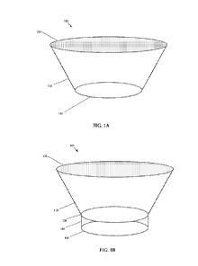
FIGURE 1A illustrates an exemplary embodiment of splatter guard 100 according
25 to the present invention. Splatter guard 100 includes a conical surface
110 having
a top edge 120 and a bottom edge 130. Bottom edge 130 forms a circle of a
diameter that approximates the diameter of a top edge of the cooking
implement.
Top edge 120 forms a circle of a diameter larger than the diameter of the
circle
formed by bottom edge 130.
Splatter guard 100 illustrates a splatter guard for a round pan, but
alternative
exemplary embodiments may be provided for square, rectangular, or any other
appropriately shaped cooking surface. Therefore, in alternative exemplary
embodiments, one or both of bottom edge 130 and top edge 120 may not be a
CA 02990188 2017-12-19
WO 2016/210338
PCT/US2016/039378
7
circle.
FIGURE 1B illustrates an exemplary embodiment of splatter guard 100 according
to the present invention including a frame, described herein as a flange.
Splatter
guard 100 includes a conical surface 110 having a top edge 120 and a bottom
edge 130. Bottom edge 130 forms a circle of a diameter that approximates the
diameter of a top edge of the cooking implement. Top edge 120 forms a circle
of
a diameter larger than the diameter of the circle formed by bottom edge 130.
io Splatter guard 100 illustrates a splatter guard for a round pan, but
alternative
exemplary embodiments may be provided for square, rectangular, or any other
appropriately shaped cooking surface. Therefore, in alternative exemplary
embodiments, one or both of bottom edge 130 and top edge 120 may not be a
circle.
Splatter guard 100 includes flange 140 extending downwards from bottom edge
130. Flange 140 may be optionally provided, and/or may be removable, and may
provide engaging edge 150 enabling a friction fit with an interior top edge
surface
of a cooking implement, for instance a pan. Some or all of the exterior of the
surface of flange 140 may contact the interior top surface edge of the cooking
implement.
FIGURE 2 illustrates splatter guard 200 which includes frame 210 and handle
220
attached to conical surface 110 for use with a cooking surface. Splatter guard
200
is illustrated without a flange, however a flange may be provided below frame
210
to provide a friction fit with a cooking implement, and/or to provide a
positioning
function for splatter guard 200 with respect to the cooking implement.
Additionally
or alternatively, a flange may be provided above frame 210 and below bottom
edge 130. Frame 210 and handle 220 may be detachable from splatter guard 200.
In a disposable exemplary embodiment made of aluminum, the skirt, the flange,
and the handle may come preassembled and may not be detachable.
CA 02990188 2017-12-19
WO 2016/210338
PCT/US2016/039378
8
In exemplary embodiments, frame 210 may be fixedly or detachably connected to
bottom edge 130. A detachable connection may be accomplished by any
appropriate method, for example a groove, a friction fit, and/or a magnet.
Frame
210 may include a downward extending flange. The flange may be of a diameter
greater than the diameter of the target cooking surface to enable a
positioning
function to be performed by the flange. The frame 210 may include handle 220
adapted to provide easy control of frame 210 and splatter guard 200 attached
thereto. Handle 220 may be detachable from frame 210.
to FIGURE 3 illustrates splatter guard 100 in an optionally deconstructed
condition,
which may be provided for shipping of the original splatter guard, and/or for
cleaning and/or storage by a user of splatter guard 100. Splatter guard 100
may
be deconstructed by detaching coupling projections 300 from one of coupling
receivers 310, 312 and 314. Coupling projections may be arranged on a line
is extending from from top edge 120 to bottom edge 130. Alternatively,
coupling
projections 300 and coupling receivers 310, 312 and 314 may be arranged in
alternative positions to provide a variety of sizes and shapes for splatter
guard
100 for use with a variety of cooking implements. Coupling projections 300 and
coupling receivers 310, 312 and 314 may be any appropriate attachment
20 mechanism, including holes paired with pins.
FIGURE 4 illustrates a side view of one coupling projection 300. Coupling
projection 300 may be composed of food-grade silicone, and may be flexible.
Coupling projection may include tip 420, locking projection 400 and post 410.
25 Post 410 may be fixedly attached to a surface of the splatter guard,
and/or may be
composed of the same material as the splatter guard. Post 410 may be attached
to the splatter guard opposite tip 420. Post 410 may have a size and shape to
match a coupling receiver, for example coupling receivers 310, 312 and 314. In
particular, post 410 may have a circular cross section, and coupling receivers
310,
30 312 and 314 may be circular holes. Coupling projection 300 may be
adapted to
be pushed through a coupling receiver by pressure provided manually. Locking
projection 400 may be deformed during the coupling process by folding down
away from tip 420 while passing through a coupling receiver, and may return to
the shape shown in Figure 4 after passing through the coupling receiver. In
this
CA 02990188 2017-12-19
WO 2016/210338
PCT/US2016/039378
9
manner, locking projection 400 may prevent coupling projection 300 from
sliding
back through the coupling receiver. Deconstructing the splatter guard may be
accomplished by exerting sufficient manual force on coupling projection 300
that
locking projection 400 deforms to pass through the coupling receiver.
FIGURE 5A is an isometric view of an exemplary embodiment of holder 500 for a
cooking splatter guard according to the present invention. Holder 500 includes
a
conical surface 510 forming a top opening 520 and a bottom opening 530. Tab
540 may optionally be provided along a top edge of top opening 520, or
to alternatively in another location. Tab 540 may form hold 550, which may
be
adapted to receive a hook for hanging a cooking splatter guard being held by
holder 500.
FIGURE 5B is an isometric view of the exemplary embodiment of holder 500
is shown in FIGURE 5A holding cooking splatter guard 100 according to the
present
invention. Cooking splatter guard 100 may be folded along a length from top to
bottom, such that at least one crease is formed that extends from the bottom
edge
to the top edge. In FIGURE 5B, inside crease 540 is positioned in the center
of
the rolled up cooking splatter guard 100, and outside crease 550 is positioned
on
20 the outside of the rolled up cooking splatter guard 100. Each of inside
crease 540
and outside crease 550 extend from the bottom edge to the top edge of cooking
splatter guard 100. In this manner, cooking splatter guard 100 may be
positioned
in holder 500. In other words, the conical section of holder 500 may form a
smaller conical section than that formed by cooking splatter guard 100, and
25 folding cooking splatter guard 100 may be required to fit cooking
splatter guard
100 in holder 500. In this folded position, holder 500 may tightly hold
cooking
splatter guard 100 and may also reduce the space occupied by cooking splatter
guard 100. The reduced spatial footprint provided by holder 500 to cooking
splatter guard 100 may be advantageous for reducing shelf space requirements
30 for a seller, as well as storage requirements by a user.
Holder 500 in FIGURE 5B may include a tab for hanging holder 500 and cooking
splatter guard 100, but this is not shown in FIGURE 5B for the sake of
clarity.
CA 02990188 2017-12-19
WO 2016/210338
PCT/US2016/039378
The sizes and angles shown in FIGURES 1A-5B are not to scale and are for
illustration purposes only.
The device is a splatter guard that rests atop a cooking utensil and is
comprised of
5 a flexible or bendable, collar-shaped (or skirt-shaped) shield that is
optionally
supported by a rigid frame (with a handle).
The device may have two elements, a shield and a frame with a handle to hold
the
shield.
to
The shield has a collar-like (or skirt like) shape whose cross section at the
base
approximates the inner contour of the frame element, and whose surface extends
upward from the base at an obtuse angle.
is The shield is made of heat-resistant, foldable material, for example
food-grade
silicone or aluminum foil. The shield is delivered to the user (i.e. packaged)
in the
folded position and is opened prior to usage. After usage, the shield may be
refolded for disposal or storage.
The frame with the handle has two functions. It holds and stabilizes the
shield in
place atop the cooking surface. When used atop a pan, the handle also allows
the
shield and the pan to be held simultaneously with a single hand. This is
useful for
sautéing and similar techniques that require the cooking surface to be moved.
The shape of the frame may approximate the shape of the rim of the cooking
implement for which it is intended. A frame intended for a round pan should
generally be round; for a square pan, square; for a rectangular griddle,
rectangular; etc.
In exemplary embodiments, the device may consist of the shield without a
frame.
In this embodiment, the exterior contour of the bottom of the shield creates a
form
fit with the interior contour of the cooking device's sides. In this
embodiment, the
rim or sides of the cooking device serve as a de facto frame for the shield.
The de
facto frame supports the shield and prevents the bottom of the shield from
CA 02990188 2017-12-19
WO 2016/210338
PCT/US2016/039378
11
reaching the cooking surface, where it may interfere with the cooking process.
In alternative exemplary embodiments, a shield and a frame are provided. The
frame has a downward-extending flange along its outside edge to prevent it
from
sliding off the cooking pan. The flange also allows a single device to be used
on
any utensil whose rim may be covered by the top of the frame while being
contained within the inside surface of the flange. In this manner, the range
of the
splatter guard's usefulness may be expanded.
to The inner contours of the frame hold the shield, such that the inner
contours of the
frame describe and match the shape of the shield near its base.
In additional alternative exemplary embodiments, a handle is not attached to
the
splatter guard, and a frame without a handle is sufficient. In still further
alternative
is exemplary embodiments, a disposable shield with or without a handle, and
with or
without a flange, is used. In these alternatives, the frame element is used
for
support and the shield folds and has an obtuse angle when in the usage
position.
In operation, the device is used by placing it atop a cooking utensil by means
of
20 either the handle or the edge of the shield. Once atop the cooking
utensil, the
device works by blocking splattering oil, other liquids, and small food
particles
from reaching the stove top or the chef. The device also has a secondary use
that
is related but distinct from preventing splatter: in cases when a cooking
device is
filled to near capacity, or beyond capacity, the skirt wall prevents food from
spilling
25 over the edge of the cooking device, as might happen when sautéing leafy
greens. After usage, the shield element of the device may be folded and
disposed
of, or cleaned and folded for storage and subsequent reuse.
Four elements make this device both unique and uniquely well-suited to its
30 function:
1) the obtuse angle of the collar, which renders the cooking surface easy to
access with implements such as tongs or spatulas.
2) the similarity in size and shape between the bottom of the collar and the
rim of
the cooking utensil to which it is adapted, which keeps the cooking surface
CA 02990188 2017-12-19
WO 2016/210338
PCT/US2016/039378
12
uncovered, allowing for the addition, removal, and manipulation of
ingredients,
and enabling vapors to escape freely.
3) the material allows the shield to be easily folded and unfolded to allow
for easy
set-up as well as space-efficient packaging, storage, and disposal.
4) in some exemplary embodiments, a rigid frame is provided to hold the shield
and stabilize the shield above the cooking vessel.
Optionally, a flange is provided to assist in placement and positioning during
the
cooking process.
In exemplary embodiments, the shield, intended for a medium size pan of about
10 inches in diameter, may be about 5 to about 7 inches high, measured from
the
top of the frame to the rim of the shield along the surface of the shield (as
opposed to vertically). A shield intended for a smaller pan may have a shorter
is wall, while a shield intended for a larger pan (or a griddle) may have a
taller wall.
Typical embodiments include a device fitted for a small pan of about 8 inches
in
diameter, and having a height of about 5 inches; for a pan of about 10 inches
in
diameter, and having a height of about 6 inches; or for a pan of about 12
inches in
diameter, and having a height of about 7 inches.
The heights of various cooking splatter guards according to the present
invention
may vary from about 7 inches by plus or minus about 3 inches. This range of
between 4 and about 10 inches may capture the majority of use cases.
Measured vertically, the shield may measure between 3.5 inches and 9 inches in
height, measured at a right angle from a horizontal plane defined by the
bottom
edge of the shield to another horizontal plane described by the top edge of
the rim
of the shield.
In exemplary embodiments, the shield, intended for a medium size pan of about
10 inches in diameter, may have a vertical height of about 4 to about 6 inches
high. A shield intended for a smaller pan may have a shorter wall, while a
shield
intended for a larger pan (or a griddle) may have a taller wall. Typical
embodiments include a device fitted for a small pan of about 8 inches in
diameter,
CA 02990188 2017-12-19
WO 2016/210338
PCT/US2016/039378
13
and having a vertical height of about 4 inches; for a pan of about 10 inches
in
diameter, and having a vertical height of about 5 inches; or for a pan of
about 12
inches in diameter, and having a vertical height of about 6 inches.
The angles of various cooking splatter guards according to the present
invention
may vary from about 120 degrees by plus or minus about 20 degrees. This range
of between about 100 and about 140 degrees may capture the majority of use
cases.
to Conventional overboil devices differ from the present invention in that
they do not
extend up as high, with sidewalls typically measuring less than 2 inches
vertically.
Additionally, typical overboil devices extend significantly over the center of
the pot,
thereby limiting access to the food cooking in the cooking implement.
Additionally,
conventional overboil devices have a higher angle (measured from the plane
is defined by a top edge of the cooking implement and the surface of the
overboil
device) than the present technology, and address a significantly different
problem,
namely overboil as opposed to splatter from a frying operation.
Overboil prevention devices address a problem that is distinct from the
problem
20 addressed by the present technology. In particular, an effective cooking
splatter
device may aim to provide as complete access as possible to the entire cooking
surface of a pan, where frying and similar cooking operations occur. In
contrast,
when boiling liquids or cooking food in boiling liquids, partial access to the
pan
and its cooking surface is sufficient for stirring contents and for advancing
the
25 cooking process. Additionally, anti-splatter devices are designed to
block small
droplets of liquid that would otherwise fly high above the surface of the
cooking
implement, whereas overboil devices are designed to prevent large volumes of
liquid from marginally overflowing a rim of a pot. Furthermore, anti-splatter
devices are typically used with pans and skillets, or other devices used for
30 sautéing, frying, etc. In contrast, overboil devices are designed for
cooking using
deep pots suitable for boiling.
CA 02990188 2017-12-19
WO 2016/210338
PCT/US2016/039378
14
This accessibility to the cooking surface is significant to the use case for
frying
and sautéing, as opposed to boiling, since when using a pan or a skillet to
fry a
burger, a steak, bacon and/or onions, the chef needs access to the entire
cooking
surface in order to manipulate the cooking food (e.g. to flip a burger with a
spatula). This access allows the chef to make effective use of the entire
cooking
surface. Additionally, when frying, searing, browning or sautéing, it is
desirable for
the area above the cooking surface to be substantially uncovered so that
vapors
can escape freely, as this facilitates proper searing and prevents the
formation of
condensation, which can redouble splatter. None of these concerns are relevant
io to boiling operations. Indeed, when boiling, it is advantageous to
partially cover
the cooking utensil, as this helps to retain steam and heat, and promotes
faster,
more efficient boiling. In overboil devices, partial coverage (or overhang) of
the
cooking area promotes the desired cooking technique (i.e. of boiling), just as
overhang and coverage detracts from non-boiling cooking techniques such as
is frying.
A thickness of the cone decreases from the bottom to the top. In other words,
a
thickness of the surface of the cooking splatter guard increases from a top
edge to
a bottom edge. The greater thickness at the bottom provides stability.
20 Additionally, tapering to a reduced thickness at the top reduces the
weight borne
by the bottom of the shield, while also decreasing material costs.
The fit of the cooking splatter guard according to the present technology
provides
substantially complete access the bottom of the cooking implement. For
instance,
25 when used in combination with a skillet or other cooking implement with
angled
side walls, the splatter guard may provide complete access to the skillet's
horizontal cooking surface. When fitted to a cooking implement with vertical
walls,
such as a sauté pan or a pot, the bottom of the splatter guard may overhang
the
horizontal cooking surface of the cooking implement by up to about 10%. In
other
30 words, if a sauté pan has a horizontal cooking surface with a diameter
of about 10
inches, then the opening in the bottom of the splatter guard adapted to use
with
the sauté pan may have a diameter of at least about 9 inches. An overhang of
about 10% provides access to a minimum of about 80% of the cooking
implement's horizontal cooking surface area. Additionally, the present
technology
CA 02990188 2017-12-19
WO 2016/210338
PCT/US2016/039378
prevents a bottom of the shield from touching a bottom of the cooking surface,
even on a shallow skillet. Furthermore, the close fit allows for some
variation of
pan sizes (e.g. the 3/4 inch variance typical amongst pans of the same nominal
size, though this prevents the same shield from being used on pans of
different
5 nominal sizes). In other words, if a shield intended fora nominal 10 inch
pan is
used on pan with a rim diameter of 9.75 inches, it will sit slightly higher up
on the
rim of the pan than if used on a pan with a rim diameter of exactly 10 inches.
The
close fit between the top of the cooking element and the bottom of a shield
according to the present technology suggests that different sized shields are
io needed for different sized pans (i.e. a 10 inch model for nominal 10
inch pans, a
12 inch model for 12 inch nominal pans, etc.).
FIGURE 6A is an isometric view of an exemplary embodiment of cooking splatter
guard 100 according to the present invention in combination with cooking
is implement 600, which may be a frying pan or skillet, or any other
cooking
implement having angled sidewalls. Cooking splatter guard 100 includes conical
surface 110 having a top edge 120 and a bottom edge 130. Conical surface 110
is also described as a sidewall, and may be about 7 inches in length, plus or
minus about 3 inches, and about 6 inches in vertical height, plus or minus
about
2.5 inches. Bottom edge 130 forms a circle of a diameter that approximates the
diameter of a top edge of cooking implement 600. In this manner, fit 610,
which
may be a friction fit, pressure fit, or a fit maintained by the weight of
cooking
splatter guard 100, is formed between of cooking splatter guard 100 and
cooking
implement 600. Since fit 610 does not limit access to the bottom surface of
cooking implement 600, access to food being fried in cooking implement 600 is
not impaired by the use of cooking splatter guard 100. Top edge 120 forms a
circle of a diameter larger than the diameter of the circle formed by bottom
edge
130.
FIGURE 6B is an isometric view of an exemplary embodiment of cooking splatter
guard 100 according to the present invention in combination with cooking
implement 620, which may be any cooking implement having vertical sidewalls,
such as a sauté pan or a pot. Cooking splatter guard 100 includes conical
surface
110 having a top edge 120 and a bottom edge 130. Conical surface 110 is also
CA 02990188 2017-12-19
WO 2016/210338
PCT/US2016/039378
16
described as a sidewall, and may be about 7 inches in length, plus or minus
about
3 inches, and about 6 inches in vertical height, plus or minus about 2.5
inches.
Bottom edge 130 forms a circle of a diameter that is slightly smaller than the
diameter of a top edge of cooking implement 620. In this manner, fit 630,
which
may be a pressure fit or a fit maintained by the weight of cooking splatter
guard
100, is formed between cooking splatter guard 100 and cooking implement 620.
Since fit 630 does not significantly limit access to the bottom surface of
cooking
implement 620, access to food being fried in cooking implement 620 is not
substantially impaired by the use of cooking splatter guard 100. For example,
the
io overhang of the bottom surface of cooking implement 620 by cooking
splatter
guard 100 may be less than 3/4 of an inch, measured horizontally from the
bottom
of the shield to the most proximate wall of the cooking implement. Top edge
120
forms a circle of a diameter larger than the diameter of the circle formed by
bottom
edge 130.
FIGURE 7 is a flow chart illustrating exemplary method 700 according to the
present invention. Method 700 begins in start circle 710, and proceeds to
operation 720, which indicates to provide a cooking splatter guard including a
surface extending up from a top edge of a cooking implement at an angle. The
angle being formed between a plane defined by a top edge of the cooking
implement and the surface is greater than 90 degrees. From operation 720, the
flow in method 700 optionally proceeds to operation 730, which indicates to
form
by the surface a fit with the top edge of the cooking implement. The top edge
of
the cooking implement is slightly larger than a bottom edge of the cooking
splatter
guard. From operation 730, the flow proceeds to operation 740, which indicates
to fry food in the cooking implement. Frying here is understood broadly as
cooking in a pan, pot, griddle, wok, or similar devices over direct heat,
usually with
or in fat or oil, but occasionally without fat, as when browning meat or
cooking
bacon. From operation 740, the flow in method 700 proceeds to end circle 750.
CA 02990188 2017-12-19
WO 2016/210338
PCT/US2016/039378
17
The above description is illustrative and not restrictive. Many variations of
the
technology will become apparent to those of skill in the art upon review of
this
disclosure. The scope of the technology should, therefore, be determined not
with
reference to the above description, but instead should be determined with
reference to the appended claims along with their full scope of equivalents.