Note: Descriptions are shown in the official language in which they were submitted.
- 1 -
VIBRATING WELDING APPARATUS AND METHOD
This application claims the benefit of the priority of USSN 62/439,691 filed
December
28, 2016; and of USSN 62/581,496 filed November 3, 2017, the specifications
and drawings
thereof being incorporated herein by reference.
Field of the Invention
This Application relates to a tool for holding an electrode, and operation
thereof.
Background of the Invention
In a number of industries it may be helpful to be able to coat a metal
substrate having
certain desired qualities with a coating of a dissimilar material having other
properties. For
example, in some cases it may be desirable to coat a metal substrate with a
ceramic surface
coating. Sometimes the coating is added for wear resistance. In the electro-
spark deposition
(ESD) process, a consumable electrode material is brought into contact with a
metallic base
surface to be treated to deposit a ceramic coating on the metallic substrate.
One such application may be for the coating of existing parts by a deposition
process.
Another application may occur where it is desired to remove or repair defects
in the surface of a
substrate, whether as a planar surface or as part of a non-planar three-
dimensional object.
Another application may pertain to welding electrodes for use in a production
line for the
sequential assembly of parts using a large number of welding stations. Welding
electrodes are
generally made of copper. The electrode may have a surface coating, such as a
ceramic coating,
that may be intended to increase electrode life. Other objects, such as steel
may be provided
with a surface coating, such as nickel or chrome. For example, coatings of
vanadium-carbide,
tungsten-carbide, titanium-diboride, zirconium-diboride, Titanium-carbide,
Cr3C2, and so on,
might be applied to tool steels or aluminum, or other metals, as may be. Such
treatments, or
coatings, or repairs may occur where it is desired to change the surface, or
near surface
properties of an object, such as hardness, or corrosion resistance or other
property.
The surface area will be coated with a layer of the electrode material when
swept by the
electrode. The electrode cap may be mounted to a moving device. The condition
of the contact
may be dependent on the relative motion of the rod of depositing electrode
coating material and
the electrode cap to be coated.
CA 2990246 2017-12-27
- 2 -
Summary of the Invention
In an aspect of the invention there is a welding apparatus for holding a
welding electrode,
the welding electrode having a long axis. The welding apparatus has a holder
in which to
receive the welding electrode. There is an electrical connection attached to
the holder, by which
to apply electricity thereto, and thereby, in use, to the welding electrode. A
first drive is
mounted to rotate the electrode holder, and thereby, in use, to cause the
welding electrode to
rotate about the long axis thereof. It has an imbalance member, and a second
drive mounted to
rotate the imbalance member about an axis off-set from the long axis of the
welding electrode.
In a feature of that aspect of the invention, the second drive is operable at
a different
frequency from the first drive. In another feature, the first drive is a DC
motor and the second
drive is an AC motor. In still another feature, either of said first drive and
said second drive is a
variable speed drive. In yet another feature, the second drive has an axis of
rotation parallel to
the first drive. In still another feature, the tool holder has a gas shield
cowling, and said
apparatus includes a gas conduit connection having a discharge oriented to
convey gas within
said cowling. In a further feature, the apparatus has a laterally extending
trigger handle. In still
another feature, an impeller is mounted to the second drive. The impeller is
driven to ventilate
the apparatus. In a yet further feature, the apparatus has a housing, and the
first and second
drives are mounted on parallel axes within that housing. In another feature,
the second drive is
independently operable from the first drive.
In another feature, the first drive has a feedback control connected to govern
output
speed. In an additional feature, the feedback control includes a digital
encoder sensor mounted
to observe output of the first drive, and a digital controller operable to
adjust motor drive speed
in response thereto. In still another feature, the first drive includes a gear
reducer. In a further
feature, the holder in which to receive the welding electrode is liquid
cooled. In another feature,
the first drive has an output speed in the range of 100 to 500 rpm. In a yet
further feature, the
second drive has an output speed of 300 to 3000 rpm. In still another feature,
the apparatus
includes an inert gas delivery manifold.
In another aspect of the invention, there is a welding apparatus for holding a
welding
electrode. The welding electrode has a long axis. The welding apparatus
includes a holder in
which to receive the welding electrode; an electrical connection attached to
the holder, by which
to apply electricity thereto, and thereby, in use, to the welding electrode; a
first drive mounted to
rotate the electrode holder, and thereby, in use, to cause the welding
electrode to rotate about the
long axis thereof; and a feedback controller mounted to govern the first
drive.
CA 2990246 2017-12-27
-3 -
In a feature of that aspect of the invention, the feedback controller has a
sensor mounted
to monitor output rotation of the holder, and an output operable to govern
motor speed in
response thereto. In another feature, the sensor includes a digital encoder,
and speed of the first
drive is digitally controlled. In a further feature, the welding apparatus has
an oscillator mounted
thereto. In yet another feature, the oscillator includes a second drive, the
second drive including
a motor and a rotational imbalance driven by the motor. In an additional
feature, the second
drive has an output speed of between 300 rpm and 3000 rpm. In another
additional feature, the
first drive has an output speed in the range of 100 to 500 rpm. In yet another
feature, the first
drive includes a gear reducer. In a yet further feature, the holder is liquid
cooled. In another
feature, the apparatus has an inert gas delivery manifold mounted to bathe the
electrode. In a
further feature, the apparatus has a removable front cover.
In yet another aspect of the invention there is a welding apparatus for
holding a welding
electrode. The welding electrode has a long axis. The welding apparatus
includes a holder in
which to receive the welding electrode; an electrical connection attached to
the holder, by which
to apply electricity thereto, and thereby, in use, to the welding electrode; a
first drive mounted to
rotate the electrode holder, and thereby, in use, to cause the welding
electrode to rotate about the
long axis thereof. The electrode holder is liquid cooled.
In a feature of that aspect, a liquid cooling jacket surrounds the electrode
holder. In
another feature the apparatus has an inert gas supply manifold having a
discharge enveloping the
electrode. In another feature, a feedback controller governs the first drive.
In a further feature,
the feedback controller has a sensor that monitors output rotation of the
holder, and an output
operable to govern motor speed in response thereto. The sensor includes a
digital encoder, and
speed of the first drive is digitally controlled. In another feature, the
welding apparatus has an
oscillator mounted thereto. In an additional feature, the oscillator includes
a second drive
including a motor and a rotational imbalance driven by the motor. In another
feature the second
drive has an output speed of between 300 rpm and 3000 rpm. In still another
feature, the first
drive has an output speed in the range of 100 to 500 rpm. In another feature,
the first drive
includes a gear reducer. In another feature, the apparatus has an inert gas
delivery manifold
mounted to bathe the electrode.
In another aspect of the invention there is an automated welding apparatus for
holding a
welding electrode, the welding electrode having a long axis. The welding
apparatus has a multi-
degree-of-freedom programmable robot. A welding head is mounted to the robot.
The welding
head includes a holder in which to receive the welding electrode. There is an
electrical
connection attached to the holder, by which to apply electricity thereto, and
thereby, in use, to
CA 2990246 2017-12-27
- 4 -
the welding electrode. A first drive is mounted to rotate the electrode
holder, and thereby, in use,
to cause the welding electrode to rotate about the long axis thereof. There is
an imbalance
member, and a second drive mounted to move the imbalance member. The second
drive is off-
set laterally from the long axis of the welding electrode.
In a feature, the second drive is operable at a different output frequency
from the first
drive. The first drive is a DC motor and the second drive is an AC motor.
Either of the first and
second drives is a variable speed drive. The second drive has an axis of
rotation parallel to the
first drive. In another feature, the tool holder has a gas shield cowling, and
the apparatus
includes a gas conduit connection having a discharge oriented to convey gas
within the cowling.
The apparatus has a laterally extending trigger handle. In another feature, an
impeller is
mounted to the second drive and is driven to ventilate the apparatus. In
another feature, the
apparatus has a housing, and the first and second drives are mounted on
parallel axes within the
housing. The second drive is independently operable from the first drive. In
still another
feature, the first drive has a feedback control connected to govern output
speed. The feedback
control includes a digital encoder sensor mounted to observe output of the
first drive, and a
digital controller operable to adjust motor drive speed in response thereto.
In another feature, the
first drive includes a gear reducer. In yet a further feature, the holder in
which to receive the
welding electrode is liquid cooled. The first drive has an output speed in the
range of 100 to 500
rpm. The second drive has an output speed of 300 to 3000 rpm. In still another
feature, the
apparatus includes an inert gas delivery manifold.
In still another feature, the first drive has a feedback controller. The
second drive is a
rotational drive offset having an axis of rotation parallel to the first
drive; the second drive is
independent of the first drive; and the holder is liquid cooled. In another
feature, the welding
apparatus has a resilient mounting by which the welding head is mounted to the
robot. In a
further feature, the welding head includes a base mounted to the robot, a
carriage slidably
mounted to the base; and a drive mounted controllably to move the carriage
relative to the base.
In a still further feature, the motion of the carriage relative to the slide
is feedback controlled. In
another feature, the holder includes a chuck, and the chuck is a quick-release
chuck for co-
operation with an automatic tool changer. In still yet another feature, the
robot is programmable
to convey the welding head along a path corresponding to a workpiece surface.
In another aspect, there is a method of using to treat a workpiece. It
includes operating
the robot to convey the welding head along a path corresponding to a workpiece
surface;
advancing the welding rod to engage to engage the workpiece; driving the rod
rotationally about
its own axis; and vibrating the rod independently of driving the rod
rotationally.
CA 2990246 2017-12-27
- 5 -
In a feature of that aspect of the invention, the method includes monitoring
contact force
on the welding rod and adjusting welding rod extension in response to force
monitored on the
welding rod. In another feature the method includes adjusting both welding rod
extension and
rotational speed of the welding rod in response to feedback. In a further
feature, the method
includes adjusting electrical duty cycle of electrical current to the welding
rod as the robot moves
the welding head relative to the workpiece. In another feature, the method
includes automated
replacement of the welding rod. In another feature, the method includes
automated replacement
of the welding rod with a welding rod of a different composition of material.
In still another
feature the method includes removing the welding rod and mounting a tool other
than a welding
tool to the welding head instead.
In yet another aspect of the invention, there is a welding apparatus for use
with a welding
electrode having a long axis. The welding apparatus includes a robot and a
welding head
mounted to the robot. The robot is programmed to convey the welding head along
a path relative
to a workpiece. The welding head has a welding electrode holder in which to
receive the
welding electrode. An electrical connection is attached to the holder, by
which to apply
electricity thereto, and thereby, in use, to the welding electrode. A first
drive is mounted to
rotate the electrode holder, and thereby, in use, to cause the welding
electrode to rotate about the
long axis thereof A feedback controller mounted to govern the first drive.
In a feature of that aspect, the feedback controller has a sensor mounted to
monitor output
rotation of the holder, and an output operable to govern motor speed in
response thereto. In
another feature, the sensor includes a digital encoder, and speed of the first
drive is digitally
controlled. In another feature, the welding apparatus has an oscillator
mounted thereto. In a
further feature, the oscillator includes a second drive, the second drive
including a motor and a
rotational imbalance driven by the motor. In another feature, the second drive
has an output
speed of between 300 rpm and 3000 rpm. In a further feature, the first drive
has an output speed
in the range of 100 to 500 rpm. In still another feature, the holder is liquid
cooled. In yet
another feature the apparatus has an inert gas delivery manifold mounted to
bathe the electrode.
In another feature, the welding head includes a base mounted to the robot, a
carriage
slidably mounted to the base; and a drive mounted controllably to move the
carriage relative to
the base. In a further feature, the robot is programmable to convey the
welding head along a
path corresponding to a workpiece surface; and motion of the carriage relative
to the slide is
feedback controlled.
CA 2990246 2017-12-27
- 6 -
In another aspect of the invention, there is a welding apparatus for holding a
welding
electrode, the welding electrode having a long axis. The welding apparatus
includes a holder in
which to receive the welding electrode, and an electrical connection is
attached to the holder, by
which to apply electricity thereto, and thereby, in use, to the welding
electrode. A first drive is
mounted to rotate the electrode holder, and thereby, in use, to cause the
welding electrode to
rotate about the long axis thereof The electrode holder being liquid cooled.
In a feature of that aspect, a liquid cooling jacket surrounds the electrode
holder. In
another feature, the apparatus includes an inert gas supply manifold that has
a discharge
enveloping the electrode. In another feature, a feedback controller is mounted
to govern the first
drive. In a further feature, the feedback controller has a sensor mounted to
monitor output
rotation of the holder, and an output operable to govern motor speed in
response thereto, the
sensor includes a digital encoder, and speed of the first drive is digitally
controlled.
I 5
In yet another feature, the welding apparatus has an oscillator mounted
thereto. In an
additional feature, the oscillator includes a second drive, the second drive
including a motor and
a rotational imbalance driven by the motor. In another feature, the second
drive has an output
speed of between 300 rpm and 3000 rpm. In another feature, the first drive has
an output speed
in the range of 100 to 500 rpm. In a further feature, the first drive includes
a gear reducer. In still
another feature the apparatus has an inert gas delivery manifold mounted to
bathe the electrode.
In another aspect of the invention there is any combination of any of the
features of any
one of embodiments shown or described herein, in combination with the features
of any other
embodiment, except to the extent those features are mutually exclusive. In
another aspect of the
invention, there is any apparatus substantially as shown or described herein,
in whole or in part.
Brief Description of the Drawings
These aspects and other features of the invention can be understood with the
aid of the
following illustrations of a number of exemplary, and non-limiting,
embodiments of the
principles of the invention in which:
Figure 1 shows a perspective view of a welding apparatus for holding a welding
electrode;
Figure 2 shows an exploded perspective view of the apparatus of Figure 1 with
near side
exterior shell removed to reveal internal details;
Figure 3 is a right-hand side view of the apparatus of Figure 1;
CA 2990246 2017-12-27
- 7 -
Figure 4 is a left-hand side view of the apparatus of Figure 1 with near-side
exterior shell
removed to reveal internal details;
Figure 5 is an end view of the apparatus of Figure 1;
Figure 6 is an exploded perspective view of the forward end of the apparatus
of Figure 1;
Figure 7 shows an exploded view of the rotating elements of the apparatus of
Figure 1;
Figure 8a shows a first embodiment of rotating shaft for the assembly of
Figure 7;
Figure 8b sows a second embodiment of rotating shaft for the assembly of
Figure 7;
Figure 9a shows a section of an alternate embodiment of welding apparatus to
that of
Figure 4, with near-side housing shell removed;
Figure 9b shows an enlarged perspective view of a detail of Figure 9a;
Figure 10a is a perspective view of a further alternative embodiment of
welding
apparatus to that of Figure 9a, with near-side half-shell cover removed;
Figure 10b is a side view of the apparatus of Figure 10a;
Figure lla is a perspective view of an alternative embodiment of the welding
apparatus
of Figure 10a;
Figure llb is a side view of the embodiment of Figure 11a;
Figure 12a is a perspective view with near side half shell cover removed of a
still further
alternative embodiment to that of Figure 9a; and
Figure 12b is a side view of the welding apparatus of Figure 12a.
Figure 13a shows a perspective view of an alternate embodiment of coating
apparatus to
that of Figure la mounted on a multi-axis robot;
Figure 13b shows a perspective view of the alternate welding or coating
apparatus of
Figure 13a, apart from the robot;
Figure 14a shows a left hand side view of the coating apparatus of Figure 13a;
Figure 14b shows a front view of the welding or coating apparatus of Figure
14a;
Figure 14c shows a right and view of the coating apparatus of Figure 14a;
Figure 14d shows a rear view of the coating apparatus of Figure 14a;
Figure 14e shows a top view of the coating apparatus of Figure 14a;
Figure 14f shows a bottom view of the coating apparatus of Figure 14a;
Figure 15a shows front view of the spindle housing of the apparatus of Figure
14a;
Figure 15b shows a cross-sectional side view of the spindle housing of Figure
15a taken
on the center line vertical plane of the spindle;
Figure 16a shows a perspective view from the right front of the coating head
of the
coating apparatus of Figure 14a, with the coating head in the fully extended
or
lowered position as when engaging a workpiece;
Figure 16b shows a perspective view from the right front of the coating head
of the
CA 2990246 2017-12-27
- 8 -
coating apparatus of Figure 14a in the raised or fully retracted position, as
when
disengaged from the workpiece'
Figure 16c shows a perspective view of from the left front of the coating head
of the
coating apparatus of Figure 14a;
Figure 16d shows a perspective view from the rear right of the coating head
for the
coating apparatus of Figure 14a;
Figure 17a shows a perspective view, from the right front, of a base or slide
assembly of
the coating apparatus of Figure 14a;
Figure 17b shows a perspective view from the left front of the assembly of
Figure 17a;
Figure 18a shows a tool and carriage of the coating apparatus of Figure 14a
from in front
and to the right;
Figure 18b shows the tool and carriage of Figure 18a from behind and to the
right;
Figure 19a shows a manual release chuck for the tool of Figure 18a;
Figure 19b is an exploded view of the chuck of Figure 19a;
Figure 19c is a side view of the chuck of Figure 19a;
Figure 19d is a cross-sectional view of the chuck of Figure 19c on '19d ¨ 19d'
of Figure
19c on the vertical centerline plane;
Figure 20a shows a quick release chuck for the tool of Figure 18a;
Figure 20b is an exploded view of the chuck of Figure 20a;
Figure 20c is a side view of the chuck of Figure 20a; and
Figure 20d is a cross-sectional view of the chuck of Figure 19c on '20d ¨ 20d'
of Figure
20c on the vertical centerline plane.
Detailed Description
The description that follows, and the embodiments described therein, are
provided by
way of illustration of an example, or examples, of particular embodiments of
the principles of the
invention. These examples are provided for the purposes of explanation, and
not of limitation, of
those principles and of the invention. In the description, like parts are
marked throughout the
specification and the drawings with the same respective reference numerals.
The drawings may
be understood to be to scale and in proportion unless otherwise noted. The
wording used herein
is intended to include both singular and plural where such would be
understood, and to include
synonyms or analogous terminology to the terminology used, and to include
equivalents thereof
in English or in any language into which this specification many be
translated, without being
limited to specific words or phrases.
CA 2990246 2017-12-27
- 9 -
For the purposes of this description, a Cartesian frame of reference may be
employed. In
such a frame of reference, the long, or largest, dimension of an object may be
considered to
extend in the direction of the x-axis, being the longitudinal axis and the
main axis of rotation.
The height of the object is measured in the z-direction, and the lateral
distance from the central
vertical plane is measured in the y-direction. Unless noted otherwise, the
terms "inside" and
"outside", "inwardly" and "outwardly", refer to location or orientation inside
the housing of the
apparatus. In this specification, the commonly used engineering terms "proud",
"flush" and
"shy" may be used to denote items that, respectively, protrude beyond an
adjacent element, are
level with an adjacent element, or do not extend as far as an adjacent
element, the terms
corresponding conceptually to the conditions of "greater than", "equal to" and
"less than".
Unless otherwise noted, the assembly shown and described herein may tend to be
symmetrical,
or largely symmetrical, about the vertical longitudinal central plane. In this
specification
distinction may be made between materials that are thermal conductors and
thermal insulators.
In general, the thermal conductors may be thought of as materials such as
metals, such as steel,
stainless steel, copper sheathing, mild steel flashing, whether galvanized or
otherwise, or
aluminum sheeting or aluminum extrusions, painted or otherwise. The insulators
may be
thought of as materials such as wood, particle board, oriented strand board,
composites, and
plastics, whether fiber reinforced or otherwise.
The embodiments illustrated and described above illustrate non-limiting
examples in
which the principles of the present invention are employed. It is possible to
make other
embodiments that employ the principles of the invention and that fall within
the following
claims. To the extent that the features of those examples are not mutually
exclusive of each
other, the features of the various embodiments may be mixed-and-matched, i.e.,
combined, in
such manner as may be appropriate, without having to resort to repetitive
description of those
features in respect of each possible combination or permutation. The invention
is not limited to
the specific examples or details given by way of illustration herein, but only
by a purposive
interpretation of the claims to include equivalents under the doctrine of
equivalents.
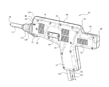
By way of general overview, a welding apparatus, such as may be identified as
an
electrode handle apparatus, or simply as a electrode handle, is shown in
Figure 1 as 20. Handle
20 has an electrode holder, indicated generally as 22, in which an electrode
24 is mounted.
Electrode 24 has a cylindrical shape, and is relatively long and thin.
Electrode 24 may be a
semi-conducting material, such as titanium carbide, titanium di-botide, or
such other welding rod
material, as may be. The outwardly extending tip of electrode 24 is seen
positioned toward an
object with which electrode 24 is to interact, i.e., that is to be subject to
welding.
CA 2990246 2017-12-27
- 10 -
Considering again handle 20, there is housing, or back-shell, or haft, or
body, generally
indicated as 30. Housing 30 includes first and second portions 32, 34, which
may be referred to
as first and second, or left hand and right hand backshell or housing halves
or housing portions.
First and second housing portions 32, 34 are held together by an array of
fasteners such as may
be in the nature of threaded cap screws 26 spaced thereabout. A gasket 28 may
be captured
between portions 32, 34, and compressed by the tightening of screws 26. Both
backshell halves
may have porting in the nature of vents such as inlet vent array 36 and outlet
vent array 38, by
which air or other gas coolant may be admitted to, and enabled to depart from,
the interior of
housing 30. The backshell halves may be made of an electrically non-
conductive, or electrically
insulating, material. The girth of housing 30 may be suitable for being gasped
or cradled in the
hand of an operator. The general proportions of housing 30 are such that it
may have a through
dimension in the transverse or y-direction of the order of 2 inches.
As assembled, housing 30 may be generally gun-shaped, i.e., it has a main body
or barrel,
or longitudinal portion 40, and a predominantly transversely projecting hand
grip portion 42.
Portion 42 may have a trigger, or activator, or switch 44. Handle 20 has a
forward end, or nose,
46 from which the welding electrode protrudes or advances in operation, and a
rearward end or
butt, or tail 48 that extends rearwardly of grip portion 42. The underside of
forward end 46 is
somewhat flared or bulbous as at 52, such that a recess 50 is formed
rearwardly thereof. In use,
the operator may support apparatus 20 with one hand in recess 50, thereby
cradling apparatus 20,
while the other hand holds grip portion 42 and operates switch 44. Switch 44
may be a variable
speed switch, e.g., in which the maximum speed of rotation of the first drive
is adjusted by
rotation of the switch about its axis, and the on-off function, and the speed
of the motor between
zero and maximum selected speed is governed by how far the trigger is
depressed axially. The
desired speed may be set, and the switch is squeezed the full distance to that
speed.
Looking at the inside of apparatus 20, each half portion 32, 34 forms a
cavity. The
halves are molded to define cavities (or two halves of one cavity) in which to
receive the
controller, circuitry, and rotating elements of handle 20. There is a first
rotating assembly 60,
and a second rotating assembly 62. Each has a respective axis of rotation,
which is, or may be
considered to be, or substantially to be, parallel to the long direction of
the main body or
longitudinal portion 40. The axis of rotation of assembly 62 is transversely
offset from, and may
conveniently be parallel to, the axis of rotation of assembly 60.
Starting with assembly 60, and proceeding from the rear of the unit to the
front, a first
drive in the form of a motor 64 is rearmost. The body or housing of motor 64
fits into a pre-
CA 2990246 2017-12-27
- 11 -
formed moulded seat in the backshell or housing, there being a corresponding
half-seat in the
other housing half. The output shaft of motor 64 extends forwardly to mate
with the input of a
coupling or clutch 68. Main drive shaft 70 has a first end that engages the
output side of clutch
68. Clutch 68 is an insulating coupling that electrically isolates motor 64
from shaft 70. Clutch
68 may also compensate for any misalignment between motor 64 and shaft 70.
Near end bearing 72 and intermediate bearing 74 are provided to carry main
shaft 70.
Near end bearing 72 is located at, or close to, the clutch-connected end of
main shaft 70.
Intermediate bearing 74 is located at roughly the half-way, or mid-point, of
main shaft 70, such
that a first portion 76 of shaft 70 is carried between bearings 72 and 74, and
a second portion 78
is cantilevered forwardly away from bearing 74. An electrical power pick-up 80
mounts on shaft
70 near first bearing 72. Power pick-up ring, 80 may typically be made of
copper, and is
connected to the welding power cable 82. In operation, ring 80 is held
stationary. Ring 80 is
externally accessible through a slot or port covered by external cover plates
84 located on the
outside of housing portions 32 and 34 forward of the rearward set of air vent
ports. A slip ring
86 is mounted axially forward of pick-up ring 80. Slip ring 86 may be a carbon-
lined slip ring.
It bears against main shaft 70 and against pick-up ring 80. In operation it
carries electrical
current from pick-up ring 80 into shaft 70. The distal, of most forward end of
shaft 70 is
enlarged at a forward shoulder into a head 88 that has a mating threaded
chuck. Chuck 90 and
head 88 co-operate to define a seat or accommodation for the inward end of
welding rod 24,
chuck 90 being releasable to permit replacement of rod 24, and may be
tightened to secure rod
24 in place, or to adjust the protruding length of rod 24.
As noted, a second drive in the form of a second rotating assembly 62 is
transversely
offset from first rotating assembly 60. It includes a motor 100, and isolation
coupling 102, a
second shaft 104 (i.e., the first shaft being main shaft 70); a pair of near
and far bearings 106,
108; an impeller 110; an eccentric weight 112 and an eccentric weight retainer
114. Motor 100
fits in a molded seat in the housing shell. In this instance, it is nested
just forward of motor 64,
above coupling 68. Shaft 104 is carried in bearings 106, 108, with coupling
102 being located
between bearing 106 and motor 100. Shaft 104 is keyed or splined forwardly of
bearing 106, for
mating with corresponding key or spline fitting of the hub of impeller 110, to
be able to impart
torque to impeller 110, and thereby to drive impeller 110 to force air to flow
through the inlet
and outlet vents or ports to permit cooling of the elements inside the
housing. Impeller 110 is
held axially in place by a transverse roll pin or grub screw. Bearing 108 is
spaced axially
forward of impeller 110, and is located between a pair of circlips.
CA 2990246 2017-12-27
- 12 -
The second drive is an oscillator used to provide a vibrational forcing
function to
apparatus. To that end, an imbalance, in the form of eccentric weight 112 is
mounted forward of
bearing 108, and is held in place by removable retainer 114. Eccentric weight
112 may therefore
be removed and replaced or adjusted to provide a different imbalance, as may
suit. Although a
rotational eccentric weight is shown, a linearly reciprocating element could
also be used. It does
not matter that shaft 100 be precisely parallel to shaft 70, although it is
convenient for making a
compact design. Shaft 100 merely needs to be such that rotation of eccentric
weight 112 results
in a forcing function having a varying component of force in a transverse
direction relative to
shaft 64, such as to cause oscillation therein (and, ultimately, at the tip of
welding rod 24).
At the front end or nose of apparatus 20 there is a closure member or closure
plate 118,
that permits access to the inside of handle 20 without having to take the two
backshell halves
apart. This access permits adjustment of eccentric weight 112. Plate 118 may
also have a gas
manifold fitting or conduit 120 which is connected to the inert gas supply
line 122 on the inside,
and which delivers that gas forwardly at the forward facing outlet or
shielding gas port. Cover
plate 118 also provides the seat for a guide bearing and gas seal 124 that
seat about the outside of
the radially outwardly facing external shoulder of head 88.
A gas shield 126 is mounted on the outside or forward face of cover plate 118.
Gas
shield 126 has a broad or somewhat bulbous of bell-shaped cowling 128 that has
a large end that
mounts about gas seal 124, and a smaller forward end that carries a tip member
130. Tip
member 130 has the form of a ceramic tube such as may be suitable for exposure
to high
temperature materials, e.g., splatter from ESD welding. When gas shield 126 is
in place,
shielding gas conveyed by line 122 is carried through plate 118 and discharged
into the shielded
chamber or duct, or passageway, or curtain, defined within cowling 128 and tip
member 130,
thereby to bathe the electrode in inert shielding gas.
At the connected end, housing 30 has three input connections, the third input
being an
inert gas supply line 122. The first input is an electrode power connection,
which may be an AC
or DC power connection, indicated as 132, and which may, ultimately, be
connected to an ESD
power source ¨ the same power source of which the opposite pole is connected
to the work piece
upon which electrode 24 is to be applied. The power source may be indicated
generically as a
power supply, discussed below. The second input is a motor power source 134
for operation of
electric motors 64 and 100 within housing 30, in the form of a power cable
which may be 120V
AC 60Hz, or 220 V AC 50Hz, or a 12V DC source, or such other source as may be,
and could be
a pneumatic source. In the embodiment shown, it may be a 24 V DC source, and
motor 64 may
CA 2990246 2017-12-27
- 13 -
be a 24 V DC Pittman variable speed motor having forward and reverse
directions controllable
by the On-Off switch. Motor 64 may be termed a low speed brush DC motor. It
may have an
operating speed range of 0 to 1800 r.p.m. In one application it has a
rotational speed of about
300 r.p.m., which would generally be considered a relatively slow speed. Motor
100 may be an
high speed DC or variable frequency AC, variable speed servo motor. Ability to
adjust both the
speed and the imbalance of the eccentric may permit the operator to choose a
setting suited to the
materials to be welded and to be applied. It may have an operating speed range
up to 3000
r.p.m., and may typically be run in the range of 500 to 1500 r.p.m. About 1000
r.p.m. is a speed
that has been used.
Figures 8a and 8b show alternate embodiments of main shaft 70. In figure 8a,
main shaft
70 is substantially cylindrical from coupling 68 to the rearward face of the
shoulder of head 88.
By contrast, in the alternate embodiment of Figure 8b, main shaft 140 is
tapered to narrow in
section longitudinally forward of the mid-pint bearing, thus making shaft 140
somewhat less stiff
than shaft 70.
The main power cable, namely that of electrode power connection 132, is
secured at a
terminal lug inside housing 30. The shielding gas conduit 122 may have the
form of a hollow
pipe that is formed to run along the inside proximal margin of housing 30.
Coolant conduit 122
may be used to conduct an inert gas, such as argon, to electrode rod 24, and
may be used for the
alternate purpose of providing an inert gas shielding to the coating process.
Conduit 122 may be
made of a non-electrically conductive material such as a plastic tube. That
portion of conduit
122 lying within housing 30 may be made of a metal, such as copper, aluminum,
stainless steel,
mild steel, or such other metal as may be suitable.
As noted, also enclosed within housing 30 is a vibration assembly, or an
oscillator, or
shaker, or motion exciter, namely assembly 62. The resultant vibration has an
amplitude having
a component in the transverse direction of electrode rod 24. In use, an
operator grasps housing
32, and uses electrode 24 much like a pencil to paint or coat the workpiece
object ¨ provided one
is accustomed to painting or writing while the pencil is oscillating. Of
course, the pencil has two
degrees of motion imposed upon it, namely rotation about the axis of the rod
(by motor 64) and
transverse deflection (by motor 100 and eccentric weight 118). The rotation of
eccentric 118
causes apparatus 20 to vibrate, which, in turn, causes electrode 24 rapidly
and repeatedly to
make and break contact with the work piece. With each oscillation there is a
new spark and
deposition of the material of electrode rod 24 onto the workpiece.
CA 2990246 2017-12-27
- 14 -
Vibration assembly 62 provides a forcing function input to the drive
transmission of rod
26, namely assembly 100, transmitting an input impulse, or wave-train of
impulses. The force
and displacement transmissibility of that transmission of the mechanical
motion of the forcing
function input to electrode 24 is dependent upon the natural frequency of the
vibrational degree
of freedom of interest. Although the axis of the cylindrical rod of electrode
24 is shown as being
parallel to the long axis of apparatus 20, this need not necessarily be so. In
another embodiment,
electrode 24 may have the form of a rod having an axis at least partially
transverse to the main
body of housing 30.
The apparatus shown and described herein may be employed for processes that
may be
termed "Low Energy Welding". That is, where there may be 1 kJ of energy used
in the heating
of a resistance spot weld, in an intermittent electrical discharge weld, the
amount of energy used
in heating at each contact of the electrode to the workpiece may be of the
order of 1 Joule. The
heating has very short time duration, is highly localised, and results in the
deposition of only a
very small amount of material. While the welding is true welding in terms of
the fusion of
materials through melting, the small energy input may tend to reduce or
substantially eliminate
any heat affected zone.
The handle apparatus drives the consumable electrode 24 to vibrate in a first
degree of
freedom of motion relative to the metallic surface being coated or treated in
the process. The
force or displacement is generated by attaching an eccentric circular metal
load to a spinning
motor. The positioning of the eccentric weight determines the pounding or
contact force when
the contacts are made. The frequency of vibration is controlled with the speed
of the motor to
which the eccentric weight is mounted. The longitudinal movement of the
consumable electrode
in a direction that includes a component of motion, and usually a predominant
component of
motion, normal to the surface to be treated, allows the periodic contacts to
be made with the
metallic surface of the workpiece. This occurs while that workpiece surface is
being driven in a
second degree of freedom of motion. The combination of motions, and the
vibration-driven urge
to make and break contact, may result in a relatively stable or consistent
sequence of electro-
sparks (when the contacts open) and depositions of coating material (when the
open contacts
approach) that take place in the process. The vibrating motion is, or may
include, motion normal
to the surface being coated.
It is known to use an ultrasonic horn to impose vibration on a welding rod.
Here,
however, an apparatus is provided that may provide secondary vibration (i.e.,
the first or
primary motion forcing function is rotation about the axis, caused by motor
64; the second
forcing function is due to motor 100 and eccentric 118), without using an
ultrasonic vibration
CA 2990246 2017-12-27
- 15 -
source. A variable speed motor and weight combination may tend to be a
relatively low cost and
robust approach to this issue.
In the embodiment of Figures 9a and 9b there is a welding apparatus 150 that
is
substantially similar to that of Figure 4. However, in addition to the
features of apparatus 20,
welding apparatus 150 has a first drive 152 that includes a speed reducer, in
this case a gear
reducer, 154, mounted at the front end of motor 156 to drop down the output
rotational speed.
Further, apparatus 150 includes a feedback control apparatus 158 that includes
a digital encoder
160 mounted to observe shaft speed. Encoder 160 is mounted between coupling
162 and near
1 0 end bearing 72. In this embodiment, it may be noted that the inert gas
delivery cowling 164
gives onto an output duct or tube 166 that has a mitred end 168 rather than a
square cut end.
By its nature, when the welding rod is depositing material on the object work
surface the
material to be deposited, at the tip of the welding rod, is heated to a molten
state. The deposited
material cools rapidly. There may be a tendency for the tip of the rod to
stick and jump. This
tendency may tend also to cause variation in the rotational output speed of
the welding rod
between a substantially instantaneous high load condition and a substantially
instantaneous no-
load condition. The use of a feedback function may permit the variation of
rotational speed to
tend to be reduced. The frequency of the digital sensor and encoder is of the
order of mHz. The
frequency of rotation of the rod may be of the order of 300 rpm, i.e., 5 Hz.
In another feature, liquid cooling is provided to electrode holder 22, in the
form of a
liquid cooling jacket 170, supplied from supply and return lines 172, 174
attached at
corresponding supply and return fittings 176. The provision of a liquid
coolant system in this
way may permit more consistent control of electrode rod temperature during
operation.
In this embodiment, apparatus 150 may also include an impeller 110. The
housing has a
shroud 178 to discourage output air from impeller 110 from recirculating back
into the input,
such that flow may start by being drawn in at the vents or ports in the
housing on one side of the
impeller and be pushed out the vents or ports on the other side.
Some embodiments may not have all of the features of Figures 9a and 9b. By way
of
example, in Figures 10a and 10b, welding apparatus 180 is substantially the
same as, or similar
to, welding apparatus 150, except that it does not employ a liquid cooling
manifold, or liquid
cooling jacket, and the motor 184 of the first drive 182 does not have a gear
reducer. It does,
however, have an output shaft speed feedback control system that includes a
digital encoder as at
186 that is used to govern the variable speed motor 184.
CA 2990246 2017-12-27
- 16 -
Similarly, In Figures 1 la and llb there is a simpler embodiment of welding
apparatus
200 that has a first drive 202 including a variable speed motor 204, but does
not have a second
drive, i.e., there is no rotating oscillator. Apparatus 200 does, however,
have an output feedback
control 206 that includes digital encoder 208 that is used to maintain a
relatively smooth output
speed of rotation of the welding rod. In the further alternate embodiment of
Figures 12a and
12b, there is a welding apparatus 220 that has a first drive 222 that has a
liquid cooling jacket
224 to cool the electrode holder, as described above. The embodiments of
Figures 10a and 10b,
lla and 11b, and 12a and 12b are intended to show that the various features
may be employed
alone or in combination.
In terms of motors, the first drive may have an AC motor or a DC motor. In one
embodiment it may be a 12VDC Pittman Brush Motor with a no-load speed of 6500
rpm and a
low speed of 500 rpm. Another embodiment of this motor may have a no-load
speed of 6200
rpm, and a low speed of 300 rpm. In another embodiment it may be a 12 VDC
servo motor with
a speed range of 200 ¨ 827 rpm; in another embodiment it may be a 24 VDC servo
motor with a
speed range of 500 ¨ 1481 rpm. In still another embodiment, the first drive
motor may be a DC
servo motor having a no load speed of 7200 rpm and a low speed of 2200 rpm.
That motor may
have a gear reducer on the output side. As the various motors are, or may be,
of different sizes,
adapters 190, 192 may be used at one or both of the front and rear end to fit
the motor into the
mounting cavity defined in the molded housing, thereby permitting any of the
motor
embodiments to be used depending on, e.g., cost and availability. There may be
a feed-back
control system that includes a digital sensor, or digital encoder, mounted to
observe output shaft
speed. Inferentially, the monitoring of motor current, which may also be
controlled, may
typically also be a measure of output shaft torque. Output shaft torque may
tend to fluctuate,
e.g., when rod contact with the workpiece is broken, or when the rod starts to
stick. The second
drive, i.e., of the oscillator, may also be either an AC drive or a DC drive.
In the embodiments of Figures 13a through 20d, there is an automated low
energy
welding (LEW) applicator unit identified as a welding or coating apparatus
300. It interfaces
with, i.e., mounts on and operates in cooperation with, a robot 250 and its
power supply. The
apparatus automatically applies LEW coatings and repairs and welds as
programmed. That is,
the robot is programmed to present the coating apparatus to a workpiece
according to a pre-
programmed path, where the path may follow the surface of the workpiece,
whether that surface
is flat or has a curvature. It may follow a particular path, as where the
operation is to lay down a
particular configuration of welding material, whether to follow a crack or
defect in making a
repair, or in building up a low energy weld of several passes, and so on.
CA 2990246 2017-12-27
- 17 -
Robot 250 is a multiple degree of freedom robot, such as may be purchased
commercially, as, for example, from ABB. In the example, the robot has a base
252 such as may
be mounted to stationary structure (e.g., a concrete floor, or other suitable
pedestal), as may be.
The workpiece is then positioned in a known location relative to robot 250.
Robot 250 may
include a laser sensing system to establish the relative location of the
workpiece. The workpiece
may itself be mounted on a pedestal or bed and may be stationary.
Alternatively, the workpiece
may be moving, as along an assembly line, whether continuously or
intermittently, according to
either a pre-determined path, or according to a path that can be sensed by the
robot such that the
relative position, orientation, and motion of the workpiece are known in the
sense of the robot
having the ability to correlate the path of tool operation to the workpiece.
For ease of
explanation, the workpiece is stationary during welding or coating, unless
otherwise noted.
Robot 250 has a first degree of freedom, namely freedom of rotation about the
vertical
axis between the robot first member, or shoulder 254 and base 252. Robot 250
has a second
degree of freedom of motion, namely angular rotation of upper arm 256 about
the shoulder joint
258. Robot 250 has a third degree of freedom of motion, namely angular
rotation of the forearm
260 relative to upper arm 256 about elbow joint 262. Elbow joint 262 may have
an axis parallel
to the pivot axis of shoulder joint 258. As such, motion of upper arm 256 and
forearm 260 can
place wrist 270 in a wide selection of positions in the radially extending
plane perpendicular to
the shoulder joint and elbow joint axes. Forearm 260 may have a further
rotational degree of
freedom about its long axis. Wrist 270 has a hand, or finger, or knuckle that
has a further
rotational degree of freedom about the pivot axis of wrist joint 272.
Apparatus 300 has a
mounting interface, or base, or plate 304 that mounts to a knuckle of robot
250, the knuckle
being carried on a spindle extending from wrist 270. That knuckle may also
have a rotational
degree of freedom about its own longitudinal spindle axis such that plate 304
may be rotated.
Plate 304 itself is mounted to a resilient intermediate member, or resilient
suspension member
306. These multiple degrees of freedom permit the welding head, i.e.,
apparatus 300, to be
oriented in a wide variety of locations and orientations to engage the
workpiece.
Apparatus 300 has a head or carriage 310 that mounts on a base, or slide, or
slides 320.
The base, or slide, or slides 320 are mounted to the resilient intermediate
member, or suspension
member, 306. Resilient suspension member 306 may include springs or springs
and dampers. In
one embodiment it may have the form of a substantially stiff polymeric plate,
which may be
made of a nylon TM or UHMW polymer. In other embodiments member 306 may be
made of a
metal, such as steel, and may be electrically insulated from the body of robot
250. While
apparently rigid, such a plate is not rigid in the manner of a thick steel
plate, and, being
CA 2990246 2017-12-27
- 18 -
polymeric, has much higher anelasticity. It is, by the nature of the material,
a damper or
moderator of high frequency vibration. The plate is substantially rectangular,
or, rather, has a
substantially rectangular mounting fitting connection footprint at which the
slide or slides, or
base 320 is attached, e.g., on the front side of resilient support member 306.
Resilient support
member 306 also has a fastener footprint corresponding to the fastener
footprint of mounting
face plate 304, which, in this case, may be a circular mounting place of a
diameter falling within
the rectangular shape of resilient suspension member 306. As shown plate 304
has a diameter
that is about half the width of the generally rectangular, or four-cornered
shape of resilient
suspension member 306. The fastener fittings at the corners of the plate,
identified at 308 may
be provided with resilient bushings or gaskets. Suspension member 306 may be
non-electrically
conductive. Suspension member 306 may tend to attenuate relatively high
frequency vibration,
such that vibration in apparatus 300 may tend to be isolated to some extent
from robot 250.
Apparatus 300 is connected through resilient suspension member 306 and
mounting plate 304.
When mounting plate 304 is installed on the spindle emanating from wrist 370,
slides 320 travel
with, and have their position, motion, and orientation dictated by the
position of wrist 370.
Carriage 310 is mounted on guideways, slides, or rails 312, 314 so that it has
a degree of
freedom of motion, in this instance in linear translation, along those
guideways. In the
orientation shown in Figure 13a, this would yield motion in vertical
translation. Clearly, the
direction of motion, whether vertical, horizontal, lateral, or some
combination of components
thereof, will be dictated by the orientation of wrist 270, and is variable
according to the
programming of robot 250. Apparatus 300 includes a drive 316 that causes
carriage 310 to move
along rails 312, 314. Drive 316 may be a screw drive, e.g., an Acme screw, or
it may be a
pneumatic or hydraulic drive. In this instance, a pneumatic drive may be
convenient. There is
also a brake, 318, which, in the embodiment illustrated is an air brake. It
could be a magnetic or
friction brake. Axial-direction drive 316 mounted is mid-way between rails
314, 314, such that
all three of items 312, 314 and 316 are roughly co-planar. While this need not
necessarily be so,
the use of a co-planar, or approximately co-planar mounting may tend to reduce
or avoid
secondary eccentric, out-of-plane forces that may not aid in the smooth
operation of apparatus
300. A symmetrical co-planar mounting may tend to be simple, and convenient.
There is also
an adjustable over-travel limit abutment, 308 rigidly mounted to carriage 310.
The adjustment
may have the form of a lag bolt, or threaded rod that is adjusted to set a
limit on upward travel of
carriage 310 relative to the base or slide or slides.
Apparatus 300 has a spindle assembly 330. In the most general case, spindle
assembly
may have a tool engagement interface 322 to which a variety of tools may be
attached ¨ drills,
CA 2990246 2017-12-27
- 19 -
arbors, mills, and so on ¨ in addition to the welding or coating equipment
described herein. Too
engagement interface 322 may include a socket for receiving the shank of the
tool. Spindle
assembly 330 is mounted in main bearings 324, 326, and a forward pilot bearing
328. Main
bearings 324, 326 may be angular contact bearings. Pilot bearing 328 may have
clearance to
accommodate vibration as induced in the apparatus. A timing gear, or pulley,
or sheave 332 is
mounted to drive the spindle shaft 334 which extends longitudinally through
the various
bearings. Shaft 334 is electrically conductive. Slip rings 336 are mounted to
the end of shaft 334
and receive power from brushes 338 (which are connected to a power supply), to
the power input
to shaft 334. Dampers, in the form of damper springs 340, 342 may be mounted
axially outside,
i.e., bracketing, main bearings 324, 326. A main spindle drive 344 is mounted
to carriage 310
and includes a motor 346 and transmission 348. The motor can be a servo motor
as described in
the embodiments above. In this instance, transmission 348 has the form of a
timing belt. It is
driven by the output pinion or pulley or sheave 350 of motor 346, and carries
motion to the input
gear, or pulley, or sheave 332 of spindle shaft 334. The timing belt is non-
electrically
conductive. As may be understood, motor 346 operates at a given motor speed,
and is
comparable to any of the main drives described above in terms of speed of
rotation. As before,
the motor speed may be digitally controlled, as by use of an encoder 352 and
associated feedback
loop. This arrangement may be substantially the same as the encoder examples
above.
Carriage 310 has first and second laterally extending structural members or
frames, such
as may be identified as a head frame 280, a tail frame 282, and left and right
hand side frames
284, 286. Head frame 280 is substantially or predominantly cylindrical, and
has an axial extent
greater than the axial spacing of main bearings 324, 326. The main bearings
324, 326 of spindle
shaft 334 of spindle assembly 330 are mounted in headframe 280. Pilot bearing
328 is likewise
mounted in tail frame 282. Side frames 284, 286 form a pair of spaced apart
axially extending
beams whose lateral spacing and orientation is governed by head frame 280 and
tail frame 282.
Similarly, side frames 284, 286 provide the structural rigidity and define the
stiffness of carriage
310 in respect of maintaining the spacing and orientation of headframe 280 and
tail frame 282
relative to each other. Upper and lower slide followers 294, 296 are mounted
to the near margins
of side frames 284, 286 to engage the slide rails, 312, 314. It may be noted
that the axial drive is
mid-way between rails 312, 314, and that all three.
Apparatus 300 also includes an offset oscillator or vibration source 360,
which, to avoid
repetition of explanation, may be the same as, or substantially the same as,
in the embodiments
above. That is, there is a vibrator servo motor 364, which drives through a
clutch 366, thereby
turning an output shaft 368 carried in bearings 372, 374. An eccentric 376 is
mounted to the far
CA 2990246 2017-12-27
- 20 -
end of driven output shaft 368. Servo motor 364 is secured in position by
mounting frames 290
that attach to the outside (i.e., furthest away from wrist 270) margins of
side frames 284, 286.
Similarly, mounting members, or frames, 292, also mounted to the outside
margins of side
frames 284, 286, secure oscillator bearings 370, 372 in position. Again, this
arrangement may be
the same as, or substantially the same as, the oscillator arrangements noted
above. The oscillator
need not be mounted on an axis parallel to the spindle axis. It is, however,
convenient, and
relatively compact, for these axes to be parallel.
Inasmuch as spindle shaft 334 is hollow, it is able to conduct shielding gas
to the tool.
To that end, a gas supply manifold 380 is provided in the form of a rotating
union shielding gas
fitting mounted to the end of shaft 334 distant from the workpiece. At the
opposite end of shaft
334 there is an 0-ring seal 382 to prevent diversion of shielding gas. The
flow of shielding gas
is governed by a solenoid controlled valve 378 having on and off positions or
conditions.
Carriage 310 is constrained to travel within a permitted range of travel. To
that end there
are left and right hand linear slides that have respective left and right hand
fixed stops 384.
Carriage 310 has upper and lower indexing fittings 386, 388 , having the form
of slide followers
294, 296 that mate with the linear slide. The upper and lower fittings
alternately bottom, or run
into, or abut, on fixed stop 384 at the upper and lower limits of travel.
A cooling jacket 390 may be mounted to carriage 310. That mounting may be to
the
distal face (i.e., the face oriented toward the workpiece) of tail frame 282.
Cooling jacket 390
may include upper and lower seals 392 that engage the outside of spindle shaft
334. Cooling
jacket 390 includes an annular cooling manifold 394 formed therein for the
circulation of liquid
coolant, and has liquid coolant inlet and outlet fittings 396, 398.
The application tool 400 is mounted at the distal end of spindle shaft 334.
Application
tool 400 may, in general, be any kind of tool that could be mounted to the end
of a robot arm or
milling machine, whether a welding or coating applicator or some other tool
such as a drill, an
end mill, an arbor, a grinder, or such as may be.
In the embodiment of Figures 19a ¨ 19d, application tool 400 is a manually
changed
welding deposition of coating tool 410. Tool 410 may be referred to generally
as a "chuck
assembly", or merely a chuck. Tool 410 includes a spindle or chuck (i.e., the
actual chuck fitting
itself, as opposed to the overall chuck assembly), indicated as 414. Chuck 414
has a root or stub
shaft 416 that fits closely within spindle shaft 334, and engages the inside
of a seal, such as an
CA 2990246 2017-12-27
- 21 -
0-ring seal or gas seal 382 mounted inside hollow spindle shaft 334. The
outside of shaft 416
includes a securement engagement fitting 420. In the embodiment shown,
securement
engagement fitting 420 has the form of an external circumferential slot or
groove or channel that
is engaged by a mating locking fitting of spindle assembly 330. Fitting 420
will include a
torque-receiving element. The locking fitting 422 (Figure 15b) may be a
circlip or
circumferential spring clip, or screw fitting, or clamp that seats in a mating
fitting of spindle
shaft 334. The locking fitting (or fittings) secure chuck 414 so that torque
is transmitted from
shaft 334 to chuck 414. In the embodiment shown, fitting 422 is a lateral key
and fitting 420 has
a geometry, such as a spline or channel, or socket that mates with the key.
Chuck 414 has a radially outwardly extending flange 424. The radially outward
margin
of flange 424 is profiled to mate with the wider portion of a shielding gas
cowling or shell, or
housing, or skirt 426 that defines within it a chamber 426. Cowling 426 is
open at its distal end,
and provides a seat for an end member that may have the form of a sleeve or
cuff 428 that is
hollow in the center and provides an outlet passage for the shielding gas.
Cuff 428 may be made
of a ceramic material. The ceramic material may tend to be suitable for high
temperature use in
a corrosive environment. In some instances cuff 428 may be mitred.
Chuck 414 has a through bore 430. The distal end of through bore 430 is
widened and
tapered to receive the shank of a collet 432, which has a matching taper.
Collet 432 has an
internal longitudinal passageway 434 that ends in an accommodation 436 for a
welding electrode
rod 440 such as may be used in operation with apparatus 300. Rod 440 will be
mad of such
welding material as suitable for the welding or coating operation, be it a
steel alloy, a nickel or
nickel alloy, an aluminum alloy, copper or a copper alloy, molybdenum or a
molybdenum allow,
titanium or a titanium alloy, or a carbide of boride ceramic composition, such
as titanium carbide
or titanium di-boride, or such other material noted hereinabove, or as may be.
An internally
threaded end piece of collet nut 438 engages the outside threads of the distal
end of chuck 414 as
at 442, causing the chamfered inside end of collet nut 438 to urge collet 432
into the tapered
mouth of bore 430, thus compressing collet 432 and clamping rod 440 in
position. Chuck 414
and collet 432 are electrically conductive, and so carry electrical current
from spindle shaft 334
into rod 440. Chuck 414 has a passageway, or conduit, or gas vent 444 by which
shielding gas
conveyed along the inside of shaft 334 is permitted to flow to chamber 426,
and thence
outwardly through cuff 428 which is mounted concentrically about rod 440.
In the embodiment of Figures 20a ¨ 20d, application tool 400 is a manually
changed
welding deposition of coating tool 450. Tool 450 may be referred to generally
as a "quick
CA 2990246 2017-12-27
- 22 -
release chuck assembly", or merely a chuck. In this case, rather than having
chuck 410 that seats
directly in the end of spindle shaft 334, a chuck 452 is seated in an
intermediate fitting, or
adapter, 448, such as may be known as an "HSK Holder". Chuck 452 is threaded
or otherwise
secured into the output end of adapter 448, and the near end of adapter 448
fits to spindle shaft
334 by a releasable securement fitting. Adapter 448 is changed by moving robot
250 to present
tool 400 to a tool changer that is designed to interact automatically with
adapter 448. The HSK
holder and the automatic tool changing equipment are available from commercial
suppliers.
From that point forward, tool 450 is substantially the same as, or similar to
tool 410,
although the gas cowling or gas shield 460 may be more compact and
predominantly
cylindrically sided, as at 462, giving a smaller internal chamber 464 since
the upstream mounting
is to the outside threaded portion of the HSK holder, as at 466, rather than
to the radially larger
flange of chuck 412 described above. Tool 450, as assembled, is shown in
Figure 20d.
In all cases, apparatus 300 and robot 250 are provided with appropriate
electrical
connectors (as at 470), pneumatic, and fluid connections, piping, and other
ancillary fittings to
supply electrical power, whether AC or DC, compressed air, and hydraulic or
cooling fluid, such
as may be required. These ancillary fittings are understood to be
conventional. Apparatus 300 is
also provided with sensors such as an inclinometer 472, as well as vibration,
motion, and force
sensors. The feedback from these sensors allows apparatus 300 to adjust as
welding is
progressing, e.g., as welding rod 440 is being consumed, it may automatically
adjust the axial
position of carriage 310 to advance toward the workpiece.
The use of an automatic tool changer and a programmable robot permits
apparatus 300 to
be used to lay down a welding pass, or a coating pass of material, be it
steel, nickel,
molybdenum, or such other material, and then, without releasing the workpiece
from its
accurately known position and orientation, to dress the surface with another
tool, be it a drill bit,
an end mill, an arbor, or a grinder, as may be appropriate to yield a
finished, machined part.
Alternatively, it permits a new welding rod to be installed without
significant delay. That is,
where more than one tool 450 is provided, one can be kept in readiness with a
new welding rod
while another tool 450 is being used. When the rod is eaten away in use, tools
450 can be
swapped out automatically. I.e., the head control automatically stops the
progress of the head,
retracts the tool to the upwardly withdrawn position, (i.e., the "datum gauge
line), and then the
machine swaps out the head. The new head has a rod that has been engaged to a
pre-set length,
set to a gauge length. The programmed machine is given the gauge length as a
known
parameter, and so returns apparatus 300 to the workpiece with the new welding
rod installed, at
CA 2990246 2017-12-27
- 23 -
the correct position and height to continue from the point of interruption
(i.e., the previous
stopping point). With the new holder tool in place, with the new electrode,
the machine moves
to the last position and restarts the LEW process where it left off (or at
such other location or for
such other task as it may have been programmed to perform after swapping one
tool for another).
The new replacement rod can be installed in the out-of-service tool 450 while
the other
tool 450 is working. This replacement can also be an automated process.
Furthermore, it is
possible to use different welding rod compositions with successive tools. For
example, a first
pass or treatment may lay down a coating of nickel on copper. A subsequent
pass may lay down
a coating of titanium carbide on the nickel. Similarly, an initial pass or
treatment may coat steel
with molybdenum, while another coating, perhaps on a different area, lays down
a pass of
titanium or a ceramic composition. In these examples, since they do not
involve a manual tool
change, apparatus 300 may be installed within a controlled environment, which
may be flushed
with shielding gas, or which may involve exposure to high temperatures or to
corrosive or
otherwise harmful processing substances.
As noted above, "Low Energy Welding" tends to involve spark deposition of
welding or
coating material in which the energy of deposit is of the order of 1 J per
spark, as opposed to a
1000 J to 10,000 J of a continuous arc weld. The spark deposition, or "Low
Energy Welding"
approach may tend to yield a very small heat affected zone. The coating
thickness may be in the
range of 0.050" (or less) up to 0.100". Up to now, Low Energy Welding has been
a hand-held
process, often dependent upon the manual skill and intuition of the operator.
Apparatus 300 may
be suitable for mounting on an existing CNC machine tool or robot that
controls the path of
coating or welding in the same manner as would be done with an end mill, while
retaining the
rotation, vibration, and peening capabilities of the above described hand-held
units. Using force,
current, and motion feedback, the apparatus adjusts electrode stick-out
according to the
controlled, programmed pattern of direction, angle, and force. The frequency
of the electrical
supply, the speed of electrode rotation, and the frequency of vibration are
all adjustable (or fixed)
as welding occurs. Spindle speed is known, because it is monitored, and can be
adjusted in real-
time, thereby tending to permit a more consistent processing of a workpiece,
and promoting
consistency of processing from workpiece to workpiece.
The coating head itself, i.e., the apparatus on carriage 310, is a sliding
coating head. It is
driven by a linear servo motor that governs axial position. The spindle can be
driven by different
motor systems, depending on the coating speed required. Encoder feedback is
provided to
permit spindle rotational speed to be monitored and adjusted (e.g.,
stabilized) during processing.
CA 2990246 2017-12-27
- 24 -
The system may provide the quick-change capability described above; a
shielding gas flushing or
flooding capability; vibration of the spindle nose; provision of electrical
power to the spindle
through the main slip-ring connection; and water cooling of the hot end of the
spindle. As
described, in the embodiments above both the electro-spark deposition (ESD)
electrical power
and the shielding gas are supplied at the rear or distant end of shaft 334 and
carried axially along
shaft 334 to the electrode.
In some embodiments, more than one welding or coating apparatus 300 may be
used at
the same time, as where multiple passes are to be made, or one material is to
be deposited upon
another, or where a large area is to be treated.
Although the various embodiments have been illustrated and described herein,
the
principles of the present invention are not limited to these specific examples
which are given by
way of illustration, but only by a purposive reading of the claims.
CA 2990246 2017-12-27