Note: Descriptions are shown in the official language in which they were submitted.
HELMET WITH FLEXIBLE STRUCTURE FOR IMPROVED FORCE ATTENUATION
Inventor:
Whitman Kwok
BACKGROUND
[0001] This disclosure generally relates to protective headgear and more
particularly to a
helmet with a flexible structure incorporated into the outer layer.
[0002] Conventional helmets include two primary components¨a rigid outer
layer and a
compressible inner layer¨that perform two non-overlapping functions. The rigid
outer layer is
made of an inflexible material and covers a user's head. The compressible
inner layer is made of
a softer material, typically a type of padding or foam, and is positioned
between the rigid outer
layer and the user's head. When a helmet with this structure is subjected to
an impact, the rigid
outer layer disperses the force of the impact over a broader area. However,
because the outer
layer is made of an inflexible material, the outer layer does not flex or
deform in any significant
manner when subjected to an impact. As a result, the rigid outer layer
transfers nearly the entire
force of the impact to the compressible inner layer, and the compressible
inner layer is the only
component of the helmet that attenuates the force of the impact. A helmet's
rigid outer layer
typically has the minimum thickness needed to provide rigidity for the purpose
of dispersing the
anticipated impact forces of the activity for which the helmet is designed.
The thickness of a
helmet's compressible inner layer is typically limited by broader design goals
like reducing the
overall size and weight of the helmet, and this leads to limited attenuation
of the impact force
relative to what would cause a mild traumatic brain injury (e.g., a
concussion).
[0003] This limitation is compounded by helmets for certain sports, such as
hockey and
lacrosse, which typically have a rigid outer layer with ridges and bumps that
protrude outward
- 1 -
CA 2990250 2017-12-28
from the user's head. These ridges and bumps act as I-beams that add
additional rigidity to the
outer layer, which can decrease the effectiveness of the portion of the
compressible inner layer
positioned directly below the ridges and bumps. Specifically, the ridges and
bumps direct impact
forces through these I-beams, bypassing the attenuation material in the cavity
of these
protrusions, which in turn further limits the attenuation of the impact force
by the helmet.
SUMMARY
[0004] A helmet includes a shell, a brim, and a flexible structure fused
together to act as a
single body. The shell is shaped to receive a user's head. The brim protrudes
from the outer
surface of the shell and is typically located in a position corresponding to
the user's forehead and
optionally proceeding around each side near the temples and ears. The flexible
structure is
positioned in a separation gap between the brim and the shell and has a higher
flexibility than the
brim and the shell.
[0005] The shell, brim, and flexible structure may be formed of a first
material, a second
material, and a third material, respectively. The first material and the
second material are
relatively rigid materials, such as ABS (acrylonitrile butadiene styrene), PC
(polycarbonate) or a
co-polyester derivative, while the third material is a more flexible material,
such as TPU
(thermoplastic polyurethane), TPE (thermoplastic elastomer), soft PLA
(polylactic acid), or
rubber. The first material and the second material may be the same.
[0006] When the helmet is subjected to an impact on the brim, the flexible
structure deforms
S0 that the brim moves relative to the shell. Although the helmet may also
include a
compressible inner layer that compresses to help attenuate the force of the
impact, the
deformation of the flexible structure provides an additional mechanism for the
helmet to
- 2 -
CA 2990250 2017-12-28
attenuate the force of an impact by extending the time of a given impact and
therefore lowering
the overall rate of acceleration experienced by the player's head. In this
design, any compressible
material directly under the brim takes part in attenuating impacts, unlike a
conventional helmet.
At the same time, the brim typically does not move below the plane of the
shell below it, which
means it does not bottom out on the user's head. The fact that the
compressible inner layer and
the flexible structure can both operate to attenuate the force of an impact
advantageously
increases the helmet's overall ability to protect the user from head trauma
associated with high-G
impacts.
BRIEF DESCRIPTION OF THE DRAWINGS
[0007] Figure (FIG.) 1A is a front perspective view of a helmet, according
to one
embodiment.
[0008] FIG. 1B is a right side view of the helmet of FIG. 1A, according to
one embodiment.
[0009] FIG. 1C is a front view of the helmet of FIG. 1A, according to one
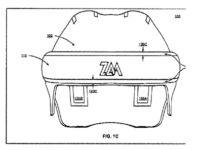
embodiment.
[0010] FIG. 1D is a top view of the helmet of FIG. 1A, according to one
embodiment.
[0011] FIG. 1E is a cross-sectional view of the helmet taken along line A-
A' of FIG. 1D,
according to one embodiment.
[0012] FIG. 2 is a cross-sectional view illustrating an example of a front
impact on the brim
of the helmet, according to one embodiment.
[0013] FIG. 3 is a top view illustrating a side impact on the brim of the
helmet, according to
one embodiment.
[0014] FIG. 4A is a rear perspective view of the helmet of FIG. 1A,
according to one
embodiment.
-3 -
CA 2990250 2017-12-28
[0015] FIG. 4B is a rotated top view of the helmet of FIG. 1A, according to
one embodiment.
[0016] FIG. 4C is a rear view of the helmet of FIG. 1A, according to one
embodiment.
[0017] FIG. 5A is a right side view illustrating a rear impact on the
ridges of the helmet,
according to one embodiment.
[0018] FIG. 5B is a top view illustrating a rear impact on the ridges of
the helmet, according
to one embodiment of the invention
[0019] The figures depict various embodiments of the present invention for
purposes of
illustration only.
DETAILED DESCRIPTION
[0020] A helmet includes a shell, a brim, and a flexible structure. The
shell is shaped to
receive a user's head. The brim protrudes from the outer surface of the shell,
covers the user's
forehead, and extends to the sides of the head to the area corresponding to
the user's temples and
ears. The flexible structure, which is made of a material that is more
flexible than the shell and
the brim, joins the brim to the shell by filling a separation gap between the
shell and the brim.
The portion of the helmet that covers the rear of the user's head includes
ridges that also protrude
from the outer surface of the shell, and additional flexible structures join
the ridges to the shell by
filling a separation gap between the shell and the ridges. When the helmet is
subjected to an
impact on the brim or the ridges, the corresponding flexible structure deforms
so that the brim or
ridge moves relative to the shell. As described herein, deformation refers to
any change in shape,
either temporary or permanent, in a material or component resulting from
physical pressure or
stress. The deformation of the flexible structure attenuates the force of the
impact, which
improves the helmet's ability to protect the user from impacts.
- 4 -
CA 2990250 2017-12-28
[0021] FIGS. 1A-1E illustrate various views of a helmet 100, according to
one embodiment
of the invention. In the embodiment shown in FIGS. 1A-1E, the helmet 100
includes, among
other elements, a shell 105 formed of a first material, a brim 110 formed of a
second material,
and a flexible structure 115 formed of a third material. The helmet further
includes two ridges
155A, 155B along its top and rear. The structure and function of the ridges
155A, 155B are
described in further detail with reference to FIGS. 4A-4B and 5A-5B. In
addition to the
components described herein, the helmet 100 can also include additional
components not shown
in the figures. For example, the helmet 100 may include a compressible inner
layer (e.g., Made
of one or more pieces of foam, padding, or air vessels) positioned between the
shell and the
user's head that helps attenuate the force of impacts to the head. Other
examples of additional
components include a chin strap that keeps the helmet 100 secure on the user's
head, a fit system
that clamps around the head to secure it on the user's head, and a face
covering, such as a visor,
face shield, or cage, that protects part or all of the user's face.
[0022] As described herein, the first material (i.e., the material used for
the shell) and the
second material (i.e., the material used for the brim) are materials with a
high rigidity and a high
impact resistance. For example, the first and second materials may be
acrylonitrile butadiene
styrene (ABS), polycarbonate (PC), or a co-polyester derivative. In some
embodiments, the first
and second materials are the same material. In other embodiments, the first
and second materials
are different materials to accommodate different impact scenarios and
anticipated forces specific
to the location of the helmet. For example, the first material is a type of
ABS while the second
material is a type of polycarbonate. As another example, the first material is
one type of
polycarbonate and the second material is a different type of polycarbonate.
[0023] As described herein, the third material (i.e., the material used for
the flexible
structure) is a material with a higher flexibility than the first and second
materials. In addition,
-5 -
CA 2990250 2017-12-28
the third material may also have a relatively low stiffness (e.g., a Young's
modulus below
50MPa), a high elongation at break (e.g., greater than 100 %), an ultimate
tensile strength of at
least 20 MPa, and a high fatigue limit (e.g., at least 10,000 cycles when
tested at half the ultimate
tensile strength of the third material). For example, the third material may
be thermoplastic
polyurethane (TPU), thermoplastic elastomer (TPE), soft polylactic acid (soft
PLA), or rubber.
[0024] In other embodiments, the shell 105 may be formed of multiple
materials that have
the characteristics described with reference to the first material and the
second material. For
example, the shell 105 may comprise an inner core made of a type of ABS
covered on all
surfaces with a layer of a different type of ABS. This allows the surfaces of
the shell 105 to be
formed of a material with some additional favorable characteristic (e.g.,
higher scratch resistance,
more easily pigmented) while the core of the shell 105 may be formed of a
material with more
favorable mechanical properties (e.g., higher rigidity, lighter weight). For
similar reasons, the
brim 110 may also be formed of multiple materials that have the
characteristics described with
reference to the first material and the second material, and the flexible
structure 115 may be
formed for multiple materials that have the characteristics described with
reference to the third
material.
[0025] FIGS. 1A, 1B, and 1C illustrate a front perspective view, a right
side view, and a front
view, respectively, of the helmet 100. Because these three figures illustrate
various views of the
same components (e.g., the shell 105, the brim 110, and the flexible structure
115), certain
aspects of these components will be described below with reference to all
three of these figures.
[0026] The shell 105 is shaped to receive a user's head. For example, the
shell 105 has a
shape that substantially matches the curvature of a human head. Because head
dimensions may
vary between users, the shape of the shell 105 may vary between different
embodiments of the
helmet 100 so that different embodiments can accommodate different groups of
users. For
- 6 -
CA 2990250 2017-12-28
example, the size of the shell 105 may vary between different embodiments of
the helmet 100 to
accommodate users with larger or smaller heads. As another example, different
embodiments of
the helmet 100 may have a shell 105 with the same circumference but with a
different width-to-
length ratio in order to accommodate different head shapes.
[0027] The brim 110 is joined to the shell 105 by the flexible structure
115. The brim 110 is
sized and shaped so that there is a separation gap 120A through 120D
(collectively referred to as
the separation gap 120) between the brim and the shell, and the flexible
structure 115 is sized and
shaped so that it occupies the separation gap 120. In the illustrated
embodiment, the shell 105
and the brim 110 are separate pieces of material. In this embodiment, the
shell 105 has an
elongated cutout at a position corresponding to the user's forehead and
temples, and the brim 110
is sized to fit in the cutout so that the separation gap 120 surrounds the
brim 110 along all four
edges of the brim 110. Specifically, the brim 110 in this embodiment has a
left vertical edge
(adjacent to the left separation gap 120A), a right vertical edge (adjacent to
the right separation
gap 120B), a top horizontal edge (adjacent to the top separation gap 120C),
and a bottom
horizontal edge (adjacent to the bottom separation gap 120D). The flexible
structure 115
surrounds these four edges of the brim 110 and joins the edges of the brim 110
to the edges of the
elongated cutout. Although the flexible structure 115 is illustrated in this
embodiment as a single
unitary piece, the flexible structure 115 may comprise multiple separate
pieces. Likewise, the
brim 110 and shell 105 may be joined directly to each other at one or more
points along the
separation gap 120 that would otherwise be occupied by the flexible structure
115.
[0028] In another embodiment, the left and right ends of the brim 110 are
joined directly to
the shell 105 with no separation gap or flexible structure 115 in between
(i.e., the left separation
gap 120A and the right separation gap 120B are omitted, and the brim 110 is
instead joined
directly to the shell 105 at these two places). Instead, the flexible
structure 115 occupies two
- 7 -
CA 2990250 2017-12-28
discrete separation gaps 120C, 120D adjacent to the top and bottom edges of
the brim 110. In
this embodiment, the brim 110 has a top horizontal edge (adjacent to the top
separation gap
120C) and a bottom horizontal edge (adjacent to the bottom separation gap
120D) but does not
have a left vertical edge or a right vertical edge.
[0029] FIG. 1D illustrates a top view of the helmet 100. In the illustrated
embodiment, the
brim 110 has a curved and elongated shape that is similar to the curvature of
the side portions
and the front portion of the shell. In this embodiment, the brim 110 is a
single continuous strip
of the second material and includes a left portion 125A at a position covering
the user's left
temple, a right portion 125B at a position covering the user's right temple,
and a center portion
125C at a position covering the user's forehead.
[0030] In other embodiments, the brim 110 may have a different structure.
In one
embodiment, the brim 110 comprises three separate pieces of the second
material, with the first
piece positioned to cover the user's left temple, the second piece positioned
to cover the user's
right temple, and the third piece positioned to cover the user's forehead.
Each of these pieces
may be curved in a manner similar to the curvature of the shell, or some or
all of the pieces may
be flat (which may simplify the manufacturing process by allowing for the use
of off-the-shelf
sheets of plastic). In this embodiment, the flexible structure 115 may fill
separation gaps
between the first, second, and third pieces of the brim 110 in addition to the
separation gap
between the brim 110 and the shell 105.
[0031] In another embodiment, the brim 110 comprises a different number of
separate pieces
(e.g., two pieces, four pieces, five pieces). In still another embodiment, the
brim 110 covers the
user's forehead but does not extend to the sides of the helmet 100 to cover
the user's temples.
For example, the brim 110 includes the center portion 125C shown in FIG. 1D
but does not
include the side portions 125A, 125B. In this embodiment, rectangular
protrusions may be
- 8 -
CA 2990250 2017-12-28
formed into the sides of the shell 110 to mimic the appearance of a brim that
extends from the
left temple to the right temple. In still another embodiment, the brim 110
extends farther toward
to rear of the helmet 100. For example, the brim 110 may extend so that the
left and right
portions 125A, 125B nearly make contact with the ridges 155A, 155B. In still
another
embodiment, the helmet 100 includes multiple brims 110. For example, the
helmet 100 may
include a lower brim that covers the user's forehead and temples in a manner
similar to the brim
110 in the illustrated embodiment in addition to an upper brim with a tighter
curvature than the
lower brim and positioned closer to the top of the user's head. An embodiment
with the ridges
arranged in this manner may be used, for example, as a lacrosse helmet.
[0032] FIG. 1E is a side cutaway view of the helmet 100 taken along the
vertical dashed line
A-A' shown in FIG. 1D. As noted above with reference to FIGS. 1A, 1B, and 1C,
the shell 105
is shaped to receive a human head. As a result, the shell 105 has a concave
inner surface 135 and
a convex outer surface 140, as illustrated in FIG. 1E. The brim 110 is joined
to the shell 105 via
the flexible structure 115 in a manner that causes the brim 110 to protrude
from the outer surface
140 of the shell 105. Because the brim 110 protrudes from the outer surface
140, an impact
object is more likely to make contact with the brim 110 rather than the shell
105 when hitting the
sides or the front of the helmet 100. Some of the advantages of having an
impact make contact
with the brim 110 are explained below with reference to FIG. 2.
[0033] In the illustrated embodiment, the shell 105 is formed of a solid
piece of the first
material. In other embodiments, the shell 105 may be formed of the first
material but with a
different internal structure. For example, the shell 105 may comprise two
layers with pockets of
air or a honeycomb structure sandwiched in between.
[0034] FIG. 2 is a cross-sectional view of the front portion of the helmet
100 illustrating an
example of a front impact 205 on the brim 110 of the helmet 100. The front
impact 205 can
- 9 -
CA 2990250 2017-12-28
represent a broad area impact (e.g., a collision with another person's head,
another person's body,
or a fixed surface such as a floor, the ground, or a wall) or a small area
impact (e.g., an impact by
a projectile such as a puck or a collision with a fixed narrow object such as
a pole or a beam).
For example, the front impact 205 may occur if the user falls forward and his
forehead hits the
floor (i.e., a broad area impact). As another example, the front impact may
occur if the user is
playing as a goalie and is hit in the forehead with a hockey puck or lacrosse
ball (i.e., a small area
impact).
[0035] When the helmet 100 is subjected to the front impact 205 shown in
FIG. 2, the impact
205 first makes contact with the front portion of the brim 110. The impact 205
causes the brim
110 to move in translation 210 toward the user's head (i.e., towards left as
shown in FIG. 2). The
motion 210, in turn, causes deformation in the flexible structure 115.
Specifically, the motion
210 causes the portion of the flexible structure 115 adjacent to the front
portion of the brim to
compress 215. Although not shown in the cross sectional view of FIG. 2, the
motion 210 may
also cause the flexible structure 115 adjacent to the side portions of the
brim 110 to shear. The
deformation of the flexible structure 115 allows the brim 110 to move in
translation relative to
the shell 105 and thus reduces motion of the shell 105 and impact to the shell
105.
[0036] The deformation of the flexible structure 115 is advantageous, among
other reasons,
because it attenuates the force of the impact 205. While the helmet 100 may
further include a
compressible inner lining that also attenuates impact forces, the deformation
of the flexible
structure 115 also attenuates the impact force, meaning that the helmet 100
has a greater overall
ability to attenuate impact forces. This advantageously causes the helmet 100
to transfer a
smaller portion of the impact force to the user's head and leads to increased
protection for the
user.
- 10 -
CA 2990250 2017-12-28
[0037] FIG. 3 is a top view illustrating a side impact 305 on the brim 110
of the helmet 100.
For example, the impact 305 could represent a player being hit in the temple
by a projectile, such
as a hockey puck or lacrosse ball. A side impact like the impact 305 shown in
FIG. 3 is one of
the most dangerous injuries in modern-day contact sports because it can cause
the user's head to
move in both translation (e.g., to the left as shown in FIG. 3) and in
rotation (e.g.,
counterclockwise as shown in FIG. 3).
[0038] When the helmet 100 is subjected to the side impact 305 shown in
FIG. 1, the
projectile makes contact with the right portion (shown in FIG. 1D as right
portion 125B) of the
brim 110. The impact 305 causes the brim 110 to make a rotational movement 310
counterclockwise about the user's neck and also causes the brim 110 to make
translational
movement 315 to the left and to the back of the user's head. Similar to the
impact 205 shown in
FIG. 2, the motion 310, 315 resulting from the impact 305 also causes
deformation in flexible
structure 115. The deformation allows the brim 110 to move in rotation and
translation relative
to the shell 105, which reduces the rotational and translational motion of the
shell 105. Again,
the deformation of the flexible structure 115 is advantageous, among other
reasons, because it
attenuates the force of the impact 305 and causes the helmet 100 to transfer a
smaller portion of
the impact's rotational and translational forces to the user's head.
[0039] FIGS. 4A, 4B, and 4C illustrate a rear perspective view, a top plan
view, and a rear
elevation view, respectively, of the helmet 100, according to one embodiment.
In addition to the
shell 105, the brim 110, and the flexible structure 115, the helmet 100
further includes two ridges
155A, 155B (collectively referred to as ridges 155) and two additional
flexible structures 160A,
160B (collectively referred to as flexible structures 160). Because these
three figures illustrate
various views of the same components (e.g., the shell 105, the ridges 155, and
the additional
- 11 -
CA 2990250 2017-12-28
flexible structures 160), certain aspects of these components will be
described below with
reference to all three of these figures.
[0040] In the illustrated embodiment, each ridge 155A, 155B has a curved,
elongated shape
that extends from a first end 170A, 170B at the top of the helmet 100
(corresponding to the top of
the user's head) to a second end 175A, 175B near the bottom rear edge of the
helmet 100
(corresponding to the occipital region of the user's head). Furthermore, the
illustrated
embodiment includes two separate ridges 155A, 155B positioned symmetrically,
with the first
ridge 155A on the left side of the helmet 100 and the second ridge 155B on the
right side of the
helmet 100. In other embodiments, the helmet 100 may include a different
number of ridges
(e.g., three ridges, with a first ridge on the left, a second ridge on the
right, and a third ridge in
the middle), shorter ridges (e.g., the ridges may start and end on the back
side of the helmet 100
without extending to the top of the helmet 100), or ridges with a different
orientation (e.g.,
horizontal ridges). In still other embodiments, the helmet may include longer
ridges. For
example, the ridges may traverse the entire length of the helmet from the
bottom edge of the
helmet, near the occipital region of the user's head, across the top (similar
to the embodiment in
Fig 1D), and optionally continuing to the front where the flexible structure
joins the shell to the
brim.
[0041] The ridges 155 are joined to the shell 105 by the additional
flexible structures 160.
Similar to the brim 110, the ridges 155 are sized and shaped to provide
separation gaps 165A
through 165F (collectively referred to as separation gaps 165) between the
ridges 155 and the
shell 105, and the flexible structures 160 are placed between the separation
gaps 165. In the
illustrated embodiment, each ridge 155 is directly joined to the shell 105
only at the first end
170A, 170B. Meanwhile, the separation gaps 165 surround each ridge on the
other three sides.
For example, the first ridge 155A has a left vertical edge (adjacent to the
left separation gap
- 12 -
CA 2990250 2017-12-28
165A), a right vertical edge (adjacent to the right separation gap 165B), and
a bottom horizontal
edge (adjacent to the bottom separation gap 165C). Similarly, the second ridge
155B has a left
vertical edge (adjacent to the left separation gap 165D), a right vertical
edge (adjacent to the right
separation gap 165E), and a bottom horizontal edge (adjacent to the bottom
separation gap
165F). In another embodiment, each ridge 155A, 155B is also joined directly to
the shell at the
second end 175A, 175B (i.e., the bottom separation gaps 165C, 165F are
omitted). In still
another embodiment, the ridges 155 are not joined directly to the shell 105 at
the first ends 170A,
170B; instead, there is a top separation gap (occupied by the additional
flexible structures 160A,
160B) separating edges of the ridges 155 from the shell 105.
[0042] In still another embodiment, the brim is omitted and the helmet
includes one or more
raised ridges that protrude at least several millimeters above the outer
surface of the shell and
extend lengthwise from the front of the helmet to the back of the helmet. An
embodiment with
the ridges arranged in this manner may be used, for example, as a cycling
helmet.
[0043] In the illustrated embodiment, the ridges 155 are formed of the
first material (i.e., the
same material as the shell 105) and are directly joined to the shell 105 at
their respective first
ends 170A, 170B. In other embodiments, the ridges 155 are formed of a fourth
material which is
different from the first material. In these embodiments, the fourth material
may still have
material properties similar to those of the first and second materials. For
example, the fourth
material may also have a high rigidity and a high impact resistance compared
to the third
material.
[0044] The ridges 155 are joined to the shell 105 in a manner that causes
the ridges 155 to
protrude from the outer surface in the rear portion of the shell 105, which
means broad area
impacts to the back of the helmet 100 make contact with the ridges 155 instead
of the shell 105.
- 13 -
CA 2990250 2017-12-28
[0045] FIGS. 5A and 5B are a side elevation view and a top plan view,
respectively, of a rear
impact 505 on the ridges 155 of the helmet 100. For example, the impact 505
could represent a
player falling backward onto the back of his head. When the helmet 100 is
subject to the rear
impact 505 shown in FIGS. 5A and 5B, an impact object is likely to make
contact with the ridges
155. The impact 505 causes the ridges 155 to move in translation 510 toward
the user's head,
and this motion 510 causes deformation in the additional flexible structures
160. Similar to the
brim 110 and the flexible structure 115, the deformation in the additional
flexible structures 160
allows the ridges 155 to move in translation relative to the shell 105, which
reduces the motion
of the shell 105 and attenuates the force of the impact 505 to the shell 105.
[0046] Although the foregoing description 100 describes a helmet 100 in
which both the
brim 110 and the ridges 155 are joined to the shell 105 (on at least some of
their edges) with
flexible structures 115 and 160, other embodiments of the helmet may include
some but not all of
these features. For example, a helmet may include a brim joined to a shell
with a flexible
structure, but with conventional ridges that are formed into the shape of the
shell (or with the
ridges being omitted). As another example, a helmet may include ridges joined
to the shell with
flexible structures, but with a conventional brim that is formed into the
shape of the shell (or with
the brim being omitted).
[0047] In one embodiment, the helmet 100 is manufactured with an additive
manufacturing
process (e.g., 3D printing) that is capable of depositing different materials
in each layer or
multiple materials in a single layer. In other embodiments, the shell 105
(with the ridges 155
directly joined to the shell 105) and the brim 110 are manufactured separately
(e.g., via injection
molding or 3D printing), and a plastic welding process is then used to join
the brim 110 to the
shell 105 by filling the separation gaps 120 and 165 with the third material
to form the flexible
structures 115 and 160. In embodiments where the ridges 155 are not directly
joined to the shell
- 14 -
CA 2990250 2017-12-28
105 (i.e., the ridges are surrounded by a separation gap on all four sides),
the ridges 155 are also
manufactured separately and then joined to the shell 105 via the plastic
welding process.
[0048] In an alternative embodiment, the shell, brim, and flexible
structure are all formed of
the same material, but the material properties of the material and the
dimensions (e.g., thickness)
of each component are selected so that the flexible structure still has a
higher flexibility than the
other components. Thus, the brim in this embodiment can still move relative to
the shell and
attenuate impact forces. Additionally or alternatively, a helmet in this
embodiment may further
include ridges and additional flexible structures formed of the same material
and with
dimensions that are similarly selected to allow the ridges to move relative to
the shell and
attenuate impact forces. For example, the material may have an ultimate
tensile strength similar
to or greater than the ultimate tensile strength of ABS (e.g., between 30 and
100 MPa) and a
greater elongation to break than ABS (e.g., the material may have an
elongation to break between
10% and 400%). These material properties allow the flexible structure to be
manufactured at a
relatively low thickness. In this example, the flexible structure has a
thickness of a few tenths of
a millimeter (e.g., between 0.1 and 0.5 mm) while the shell and the brim have
a significantly
higher thickness (e.g., between 1.0 and 5.0 mm). The inherent lack of material
resulting from the
low thickness of the flexible structure results in a flexibility that is
similar to the flexibility of a
thicker flexible structure formed with a more flexible material (such the
third material described
above). This combination of material properties and dimensions allows the
entire helmet to be
manufactured from a single material while still retaining many of the
desirable properties
described herein, such as the ability for the flexible structure to attenuate
impact forces.
[0049] Although the description in this disclosure is provided with
reference to a helmet, in
other embodiments the structural components described herein may be applied to
other forms of
protective headgear that cover a smaller portion of the user's head than a
helmet. For example, a
- 15 -
CA 2990250 2017-12-28
headband may include a flexible structure that allows a first portion of the
headband to move
relative to a second portion of the headband to help attenuate impact forces.
As another example,
a pair of eye goggles may include a flexible structure that allows each eye
covering (or a portion
of each eye covering) to move relative to one or more other portions of the
goggles. In these
embodiments, the protective headgear may include multiple distinct components
fastened
together (e.g., with buttons, clips, or straps).
[0050] The foregoing description of the embodiments of the invention has
been presented for
the purpose of illustration; it is not intended to be exhaustive or to limit
the invention to the
precise forms disclosed. Persons skilled in the relevant art can appreciate
that many
modifications and variations are possible in light of the above disclosure.
[0051] All dimensions, materials, and specific numbers shown in the
embodiments are given
only by way of example, in order to aid the understanding of the invention;
none of them are
meant to limit the present invention, unless it is explicitly stated so.
[0052] Finally, the language used in the specification has been principally
selected for
readability and instructional purposes, and it may not have been selected to
delineate or
circumscribe the inventive subject matter. It is therefore intended that the
scope of the invention
be limited not by this detailed description, but rather by any claims that
issue on an application
based hereon. Accordingly, the disclosure of the embodiments of the invention
is intended to be
illustrative, but not limiting, of the scope of the invention, which is set
forth in the following
claims.
- 16 -
CA 2990250 2017-12-28