Note: Descriptions are shown in the official language in which they were submitted.
CA 02990676 2017-12-21
WO 2017/004535 PCT/US2016/040725
MEDICAL DEVICE ADAPTER
Cross Reference to Related Application
This application claims the benefit of U.S. Patent Application 15/196,952
filed
June 29, 2016 and U.S. Provisional Patent Applications 62/188,363, filed July
2, 2015,
62/249,482 filed November 2, 2015, 62/279,858 filed January 18, 2016, and
62/325,700
filed April 21, 2016 the entireties of which applications are hereby
incorporated by
reference into this application.
Background of the Invention
Field of the Invention
The present invention relates generally to a design of an adapter for a
medical
device for use in the body and more specifically to an adapter intended to
convert or
augment the medical device, for example a catheter, such that the purpose or
configuration of the medical device is modified or expanded.
Description of the Related Art
Catheter type devices are typically long tubular structures with an inner
lumen
suitable for a guidewire used to navigate the vasculature, inject contrast or
therapeutic
materials, aspirate thrombus, or provide a means to deliver other devices or
therapies to a
target site within the vasculature or other body lumen. Catheter type devices
are typically
inserted through a small opening in the skin or another opening under visual
guidance
tracked to the target location within the body.
U.S. Patent Application Publication No. 2007/0244440 discloses a medical
device
including a catheter with an expandable tip for use with at least two
different sizes of
wire guides. The catheter includes a wire guide lumen sized to receive a first
wire guide
of a first diameter. The catheter may also include a tip lumen that extends in
a distal
direction from a first opening in communication with the wire guide lumen to a
second
opening. The first opening is sized to receive the first wire guide, and the
second opening
is sized to receive a second wire guide of a smaller diameter than the first
wire guide. The
catheter also includes one or more longitudinal expansion features capable of
radially
expanding the tip lumen to receive a wire guide of a diameter up to the first
diameter
through the second opening.
1
CA 02990676 2017-12-21
WO 2017/004535 PCT/US2016/040725
U.S. Patent No. 8,100,884 discloses an adapter assembly for connecting a
catheter
assembly to a tunneler having a generally tubular body having a first end, a
second end
and a longitudinal axis extending there through between the first end and the
second end.
The first end of the adapter is constructed to engage the proximal end of a
trocar. The
second end of the adapter is constructed to releasably engage at least one
catheter lumen.
A slider is disposed about the adapter and is longitudinally slidable along
the adapter.
When the slider is slid towards the second end of the adapter, the slider
engages a
plurality of legs on the adapter and biases the plurality of legs toward each
other and the
longitudinal axis of the adapter.
U.S. Patent No. 8,523,840 discloses coupler assemblies to be used with a
catheter
to connect a proximal end of the catheter to extracorporeal medical equipment.
An
exemplary coupler assembly includes a spherical linkage coupler for a
catheter. The
coupler comprises a first cylinder portion for connecting to a structure, and
a second
cylinder portion for connecting to a distal end of a body of the catheter. The
coupler also
comprises a spherical linkage including at least two link arms. Each of the
two link arms
are connected on one end to the first cylinder portion and on the other end to
the second
cylinder portion. The two link arms connect a portion of the structure to the
distal end of
the catheter and enable the structure to move relative to the distal end of
the catheter in
response to an external force exerted on the structure.
It is desirable to provide an improved adapter designed with features that
expand,
augment, or modify the configuration or intended use of a medical device. The
adapter
including geometry, mechanical and/or thermal properties to expeditiously
attach to the
medical device, such as a catheter. In one embodiment, the adapter provides
conversion
of the medical device from a single guidewire device to a two guidewire
device.
Summary of the Invention
In accordance with the present invention, an adapter is constructed to have a
proximal portion that interfaces with the internal lumen of a medical device
and a distal
portion that modifies, augments or extends the configuration or intended use
of the
medical device. The medical device can be a catheter. The proximal portion of
the
adapter interfaces with the internal lumen of the medical device in a manner
to secure the
2
CA 02990676 2017-12-21
WO 2017/004535 PCT/US2016/040725
adapter to the medical device during use. The distal portion of the adapter is
generally
outside the lumen of the catheter or device and is designed with features that
expand,
augment, or modify the configuration or intended use of the medical device.
The proximal portion of the adapter is designed to provide an interference fit
with
an internal lumen of the medical device such that during subsequent use the
adapter
remains secure. The proximal portion is additionally designed to be easily
inserted into
the internal lumen of medical device. In one embodiment, the proximal portion
of the
adapter includes a coil structure having geometry and mechanical/thermal
properties such
that the structure is slightly smaller than the internal lumen to fit within
the internal
lumen in the operating room environment temperature and then expands to a
larger size
to secure the adapter to the internal lumen of the medical device when it is
in-vivo closer
to body temperature. For example, the coil structure can be formed of nitinol
at a
predetermined austentic finish (AF) temperature less than body temperature but
greater
than the temperature typically expected in an operating room or catheter lab.
Alternatively, the coil structure can be physically restrained to have a size
smaller than
the internal lumen in the operating room environment and then expands to
interface with
the internal lumen of the medical device once the adapter is seated with the
medical
device and the physical restraint is removed. Alternatively, the coil
structure can be
configured to compress as it is inserted into the internal lumen of the
medical device and
provide securement.
The proximal portion can include an internal lumen to preserve a path for a
guidewire, or for contrast injection for example. The proximal portion can
include a
braided structure or slotted tube stent-like geometry which can be compressed
to a
smaller size and then expanded to secure the adapter to the internal lumen of
the catheter
or other device.
The distal portion of the adapter can be used to modify the configuration of
the
medical device, for example, to convert a medical device from a single
guidewire device
to a two (2) guidewire device.
3
CA 02990676 2017-12-21
WO 2017/004535 PCT/US2016/040725
Brief Description of the Drawings
The foregoing description, as well as further objects, features, and
advantages of
the present invention will be understood more completely from the following
detailed
description of presently preferred, but nonetheless illustrative embodiments
in accordance
with the present invention, with reference being had to the accompanying
drawings, in
which:
Fig. IA is a schematic, longitudinal, cross-sectional view of an embodiment of
an
adapter in accordance with the teachings of the present invention and a
partial schematic,
longitudinal, cross-sectional view of a distal end of a medical device.
Fig. 1B is an enlarged detail view of Fig. IA, showing a proximal end of the
adapter.
Fig. IC is an enlarged detailed view of Fig. IA, showing part of a distal
portion of
the adapter.
Fig. 2 is a schematic, longitudinal, cross-sectional view of the adapter where
the
coil of the adapter has been elongated in order to reduce the size of the coil
prior to
insertion into the target medical device. Break line symbols are utilized to
reduce the size
of the drawing for clarity.
Fig. 3 is a schematic, longitudinal, cross-sectional view of the adapter where
the
coil of the adapter has been rotated or twisted in order to reduce the size of
the coil prior
to insertion into the target medical device. Break line symbols are utilized
to reduce the
size of the drawing for clarity.
Fig. 4 is a schematic, longitudinal, cross-sectional view of an alternate
embodiment of an adapter, and a partial schematic, longitudinal, cross-
sectional view of a
distal end of a medical device. Break line symbols are utilized to reduce the
size of the
drawing for clarity.
Fig. 5 is a schematic, longitudinal, cross-sectional view of an alternate
embodiment of an adapter, and a partial schematic, longitudinal, cross-
sectional view of a
distal end of a medical device. Break line symbols are utilized to reduce the
size of the
drawing for clarity.
4
CA 02990676 2017-12-21
WO 2017/004535 PCT/US2016/040725
Fig. 6 is a schematic, longitudinal, cross-sectional view of an alternate
embodiment of an adapter, and a partial schematic, longitudinal, cross-
sectional view of a
distal end of a medical device. Break line symbols are utilized to reduce the
size of the
drawing for clarity.
Fig. 7 is a schematic, longitudinal, cross-sectional view of an alternate
embodiment of an adapter, where a coil of the adapter has been rotated or
twisted in order
to reduce the size of the coil prior to insertion into the medical device.
Break line
symbols are utilized to reduce the size of the drawing for clarity.
Fig. 8A is a schematic, longitudinal, cross-sectional view of an adapter
according
an embodiment of the invention. Break line symbols are utilized to reduce the
size of the
drawing for clarity.
Fig. 8B is an enlarged detail view of Fig. 8A, showing a distal portion of the
adapter.
Fig. 8C is an enlarged detail view of Fig. 8A, showing a proximal end of a
distal
portion of the adapter.
Fig. 8D is an enlarged detail view of Fig. 8A, showing a distal end of a
distal
portion of the adapter.
Fig. 8E is an enlarged detail view of Fig. 8A, showing a proximal portion of
the
adapter.
Fig. SF is an enlarged detail view of Fig. 8A, showing a proximal end of a
proximal portion of the adapter.
Fig. 9A is a schematic, longitudinal, cross-sectional view of an adapter
according
an embodiment of the invention. Break line symbols are utilized to reduce the
size of the
drawing or schematic for clarity.
Fig. 9B is an enlarged detail view of Fig. 9A, showing a distal portion of the
adapter
Fig. 9C is an enlarged detail view of Fig. 9A, showing a proximal portion of
the
adapter.
Fig. 9D is an enlarged detail view of Fig. 9A, showing a distal end of a
distal
portion of the adapter.
5
CA 02990676 2017-12-21
WO 2017/004535 PCT/US2016/040725
Fig. 9E is an enlarged detail view of Fig. 9A, showing a proximal end of a
distal
portion of the adapter.
Fig. 9F is an enlarged detail view of Fig. 9A, showing a proximal end of a
proximal portion of the adapter.
Fig. 9G is an enlarged detail view of Fig. 9A, showing middle elements of a
proximal portion of the adapter.
Fig. 9H is an enlarged detail view of Fig. 9A, showing a distal end of a
proximal
portion of the adapter.
Fig. 10A is a schematic, longitudinal, cross-sectional view of an adapter
according to an embodiment of the invention having two coil elements in a
proximal
portion of the adapter. Break line symbols are utilized to reduce the size of
the drawing
for clarity.
Fig. 10B is an enlarged detail view of Fig. 10A, showing a distal portion of
the
adapter.
1.5 Fig. IOC is an enlarged detail view of Fig. 10A, showing a proximal
portion of the
adapter.
Fig. 10D is an enlarged detail view of Fig. 10A, showing a proximal end of a
proximal portion of the adapter.
Fig. 10E is an enlarged detail view of Fig. 10A, showing a distal end of a
distal
portion of the adapter.
Fig. 1OF is an enlarged detail view of Fig. 10A, showing the proximal coil
element, coil located closer to the proximal end of the proximal portion of an
adapter.
Fig. 10G is an enlarged detail view of Fig. 10A, showing the distal coil
element,
coil located closer to the distal end of the proximal portion of an adapter.
Fig. 11A is a schematic, longitudinal, cross-sectional view of an adapter
according an embodiment of the invention where a distal coil element of the
adapter has
been rotated or twisted in order to reduce the size of the coil prior to
insertion into the
target catheter or device. Break line symbols are utilized to reduce the size
of the drawing
for clarity.
6
CA 02990676 2017-12-21
WO 2017/004535 PCT/US2016/040725
Fig. 11B is an enlarged detail view of Fig. 11A, showing a proximal portion of
the
adapter.
Fig. 11C is an enlarged detail view of Fig. 11A, showing a distal end of a
proximal portion of the adapter.
Fig. 11D is an enlarged detail view of Fig. 11A, showing a distal end of a
proximal portion of the adapter and a proximal end of a distal portion of the
adapter.
Fig. 12A is a schematic, longitudinal, cross-sectional view of an adapter
according to an embodiment of the invention and a partial schematic,
longitudinal, cross-
sectional view of a distal end of a medical device, where a distal coil
element of the
adapter has been rotated or twisted in order to reduce the size of the coil
prior to insertion
into the target medical device and the proximal coil element that has been
inserted into
the medical device causing the proximal coil element to elongate and reduce in
diameter.
Break line symbols are utilized to reduce the size of the drawing for clarity.
Fig. 12B is an enlarged detail view of Fig. 12A, showing a proximal portion of
the
adapter.
Fig. 12C is an enlarged detail view of Fig. 12A, showing a proximal end of a
proximal portion of the adapter, including a proximal coil element.
Fig. 12D is an enlarged detail view of Fig. 12A, showing a distal end of a
proximal portion of the adapter and a proximal end of a distal portion of the
adapter.
Fig. 13A is a schematic, longitudinal, cross-sectional view of an adapter
according to an embodiment of the invention and a partial schematic,
longitudinal, cross-
sectional view of a distal end of a medical device, where a distal coil
element of the
adapter has been rotated or twisted in order to reduce the size of the coil
prior to insertion
into the medical device then subsequently released to expand to an inner lumen
of the
medical device, and a proximal coil element that has been inserted into the
medical
device causing the proximal coil element to elongate and reduce in diameter.
Break line
symbols are utilized to reduce the size of the drawing for clarity.
Fig. 13B is an enlarged detail view of Fig. 13A, showing a proximal portion of
the
adapter.
7
CA 02990676 2017-12-21
WO 2017/004535 PCT/US2016/040725
Fig. 13C is an enlarged detail view of Fig. 13A, showing a proximal end of a
proximal portion of the adapter, including a proximal coil element.
Fig. 13D is an enlarged detail view of Fig. 13A, showing a distal end of a
proximal portion of an adapter and a proximal end of a distal portion of the
adapter.
Fig. 14A is a partial schematic, longitudinal, cross-sectional view of an
adapter
according to an embodiment of the invention and a partial schematic,
longitudinal, cross-
sectional view of a distal end of a medical device, where a coil element of
the adapter has
been rotated or twisted in order to reduce the size of the coil prior to
insertion into a
medical device then subsequently released to expand to an inner lumen of the
medical
device, and a transverse cross-sectional view Z-Z of a distal portion of the
adapter. Break
line symbols are utilized to reduce the size of the schematic for clarity
Fig. 14B is an enlarged detail view of Fig. 14A, showing a proximal end of a
distal portion of an adapter.
Fig. 14C is an enlarged detail view of Fig. 14A, showing a distal end of a
distal
portion of the adapter and a transverse cross-sectional view Z-Z of a distal
portion of the
adapter.
Fig. 15A is a partial schematic, longitudinal, cross-sectional view of an
adapter
according an embodiment of the invention and a partial schematic,
longitudinal, cross-
sectional view of a distal end of a medical device, where a coil element of
the adapter has
been rotated or twisted in order to reduce the size of the coil prior to
insertion into the
medical device then subsequently released to expand to an inner lumen of the
medical
device and a first and second wire, and a transverse cross-sectional view Z-Z
of a distal
portion of the adapter. Break line symbols are utilized to reduce the size of
the schematic
for clarity,
Fig. 15B is an enlarged detail view of Fig. 15A, showing a proximal end of a
distal portion of the adapter.
Fig. 15C is an enlarged detail view of Fig. 15A, showing a distal end of a
distal
portion of the adapter and a transverse cross-sectional view Z-Z of a distal
portion of the
adapter.
8
CA 02990676 2017-12-21
WO 2017/004535 PCT/US2016/040725
Fig. 16A is a partial schematic, longitudinal, cross-sectional view of an
adapter
according to an embodiment of the present invention and a partial schematic,
longitudinal, cross-sectional view of a distal end of a medical device, where
a coil
element of the adapter has been rotated or twisted in order to reduce the size
of the coil
prior to insertion into the medical device then subsequently released to
expand to an inner
lumen of the medical device, which also includes a first and second wire, and
a transverse
cross-sectional view Z-Z of a distal portion of the adapter. Break line
symbols are
utilized to reduce the size of the schematic for clarity,
Fig. 16B is an enlarged detail view of Fig. 16A, showing a proximal end of a
distal portion of the adapter.
Fig. 16C is an enlarged detail view of Fig. 16A, showing a distal end of a
distal
portion of the adapter and a transverse cross-sectional view Z-Z of a distal
portion of the
adapter.
Fig. 17A is a partial schematic, longitudinal, cross-sectional view of an
adapter
according to an embodiment of the invention and a partial schematic,
longitudinal, cross-
sectional view of a distal end of a medical device, where a coil element of
the adapter has
been rotated or twisted in order to reduce the size of the coil prior to
insertion into the
target medical device then subsequently released to expand to an inner lumen
of the
medical device, and a transverse cross-sectional views Z-Z and Y-Y.
Fig. 17B is an enlarged detail view of Fig. 17A, showing a proximal end of a
distal portion of the adapter.
Fig. 17B is an enlarged detail view of Fig. 17, showing a distal end of a di
stal
portion of the adapter and a transverse cross-sectional views Z-Z and Y-Y.
Fig. 18A is a partial schematic, longitudinal, cross-sectional view of a
proximal
portion of an adapter according to an embodiment of the invention. Break line
symbols
are utilized to reduce the size of the drawing or schematic for clarity.
Fig 18B is a partial schematic, longitudinal, cross-sectional view of a
proximal
portion of the adapter shown in Fig. 18A, where the adapter and proximal
portion has
been inserted into a medical device. Break line symbols are utilized to reduce
the size of
the drawing or schematic for clarity.
9
CA 02990676 2017-12-21
WO 2017/004535 PCT/US2016/040725
Fig 18C is a partial schematic, longitudinal, cross-sectional view of a
proximal
portion of the adapter shown in Fig. 18A, where the adapter and proximal
portion has
been inserted into a target medical device and a tensile force has been
transmitted to a
central tube axially compressing a portion of a coil. Break line symbols are
utilized to
reduce the size of the drawing or schematic for clarity.
Fig 18D is a partial schematic, longitudinal, cross-sectional view of a
proximal
portion of the adapter, where the adapter and proximal portion has been
inserted into a
target medical device and a tensile force has been transmitted to a central
tube axially
compressing a portion of a coil. Break line symbols are utilized to reduce the
size of the
drawing or schematic for clarity.
Fig 18E is an enlarged detail view of Fig 18C showing a compressed portion of
the coil.
Fig 18F is an enlarged detail view of Fig 18D showing a compressed portion of
the coil.
Fig. 19 is a partial schematic, longitudinal, cross-sectional view of a
proximal
portion of an adapter according to an embodiment of the invention. Break line
symbols
are utilized to reduce the size of the drawing or schematic for clarity.
Fig. 20A is a partial schematic, longitudinal, cross-sectional view of a
proximal
portion of an adapter according to an embodiment of the invention. Break line
symbols
are utilized to reduce the size of the drawing or schematic for clarity.
Fig 20B is an enlarged detail view of Fig 20A.
Fig 21A is a partial schematic, longitudinal, cross-sectional view of an
adapter
according to an embodiment of the invention, where the adapter has been
inserted into a
target medical device. Break line symbols are utilized to reduce the size of
the drawing or
schematic for clarity.
Fig 21B is an enlarged detail view of Fig 21A.
Detailed Description of the Preferred Embodiments
Reference will now be made in greater detail to preferred embodiments of the
invention, examples of which is illustrated in the accompanying drawings.
Wherever
CA 02990676 2017-12-21
WO 2017/004535 PCT/US2016/040725
possible, the same reference numerals will be used throughout the drawings and
the
description to refer to the same or like parts.
Fig. 1A, Fig. 1B, and Fig. 1C illustrates one embodiment of adapter 10 coupled
to
distal end 201 of medical device 200. A suitable medical device 200 is a
catheter.
Adapter 10 includes distal portion 20 and proximal portion 30. Proximal
portion 30 is
predominately or entirely inside lumen 211 of target medical device 200.
Distal portion
20 of adapter 10 is predominately outside of target medical device 200.
Adapter 10 is co-
axial with medical device 200 as shown by longitudinal axis 11. Proximal
portion 30 of
adapter 10 includes coil 12. Preferably coil 12 can be made of nitinol. Coil
12 can be
comprised of wire with a cross-sectional size wound to form a general coil
shape.
Coil 12 interfaces with lumen 211 of medical device 200 in a manner that
secures
adapter 10 to medical device 200. Adapter 10 can be secured to medical device
200 by
an interference fit of coil 12 with lumen 211. Coil 12 can have an austenitic
finish
temperature (Af) less than body temperature, such as an average of 37 C of
normal body
temperature. and greater than a temperature typically expected in an operating
room or
catheter lab, for example about 25 degrees to about 30 degrees C. Coil 12 can
be twisted
and or elongated to reduce a size or diameter of coil 12 such that coil 12 has
a smaller
size or diameter than a size or diameter of lumen 211 to facilitate
positioning adapter 10
inside medical device 200. As adapter 10 warms to body temperature during use
in-vivo,
coil 12 can expand to provide additional securement to medical device 200.
Alternatively, coil 12 can be designed to be physically restrained or
constrained to
have a size or diameter smaller than internal lumen 211 of medical device 200
in an
operating room environment and coil 12 can expand to interface with the
internal lumen
211 of the target catheter or device 200 when the physical restraint is
removed, once the
adapter 10 is seated within medical device 200. Coil 12 is shown with a
constant round
cross-section, alternatively the coil 12 can have a rectangular cross-section
of a flat wire
coil design. A flat wire design provides the benefit of a lower profile coil
12 but still
sufficient securement through an interference fit with lumen 211. The cross-
section can
be variable along the length of coil 12. A variable cross-section coil 12
design provides
11
CA 02990676 2017-12-21
WO 2017/004535 PCT/US2016/040725
the advantage of biased securement either towards one of ends of adapter 10.
Coil 12 can
have variable flexibility and bending about longitudinal axis 11.
In one embodiment, coil 12, provides additional reinforcement of medical
device
200 to improve the kink resistance. Adapter 10 includes tube 16 coupled to
distal portion
20 of adapter 10 and is co-axial with coil 12. Tube 16 has funnel portion 13
located at
proximal end 30 of adapter 10. Funnel portion 13 can facilitate tracking of a
guide wire
from a proximal end (not shown), of medical device 200 to distal portion 20 of
adapter
10. Tube 16 preferably is a polymer tube and can include braiding or other
reinforcement. Coil 12 includes proximal end 15 that is coupled, bonded or
otherwise
attached near proximal end 19 of tube 16. Proximal end 15 of coil 12 can be
retained to a
size smaller than a size of lumen 211 to facilitate loading of adapter 10 into
medical
device 200 in use. Distal end 14 of coil 12 can be retained to a size smaller
than a size of
lumen 211. For example, proximal end 15 or distal end 14 can be heat shaped or
formed
to a smaller size than the size of lumen 211.
Distal end 14 provides a location on coil 12 that can be grabbed or held in
order
to twist and or elongate coil 12 to make it smaller in size to facilitate
positioning the
adapter 10 inside medical device 200. Distal portion 20 of adapter 10 is
preferably made
from a thermoplastic elastomer. Example thermoplastic elastomers or soft
polymers
include, polyether urethane and polyether block amide, such as for example
¨40D
PEBAX manufactured by Arkema.
In this embodiment, distal portion 20 is designed to modify medical device 200
that has a single guidewire access to have a two guidewire access. Distal
portion 20
includes first lumen 21 for a first guidewire and second lumen 22. Second
lumen 22
connects to lumen 211 of medical device 200 by way of tube 16 of adapter 10.
This
allows the user extra flexibility, for example to exchange guidewires, or
administer
contrast or medications through the target catheter or device lumen 211. The
path of a
first guidewire illustrated by first lumen centerline 23 and the path of a
second guidewire
is illustrated by the second lumen centerline 24. Accordingly, the path of
lumen
centerline 23 is outside of device 200.
12
CA 02990676 2017-12-21
WO 2017/004535 PCT/US2016/040725
Distal portion 20 includes reduced size portion 17 at proximal end 26 of
distal
portion 20 which is designed through choice of materials, for example
thermoplastic
elastomers or soft polymers and geometry to interface with lumen 211 of
medical device
200. A slight interference fit between reduced size portion 17 and lumen 211
provides a
stable structure during introduction of the coupled adapter 10 and medical
device 200
into a body cavity or vessel. Adapter 10 can include a tapered distal end 27
of distal
portion 20 which facilitates tracking the medical device 200 with attached
adapter 10
inside a body lumen.
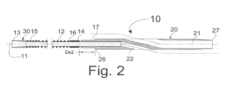
Fig. 2 illustrates adapter 10 in a configuration where coil 12 has been
reduced to a
smaller size by elongating coil 12. Fig. 3 illustrates adapter 10 in a
configuration where
the coil 12 has been reduced to a smaller size by rotating or twisting coil
12. An alternate
embodiment of adapter 10 is where a combination of coil 12 twisting and
elongating
reduces the size of coil 10 such that it can fit within medical device 200.
Distance Ds2
between distal end 14 of coil 12 and proximal end 26 of distal portion 20 in
Fig. 2 and
Fig. 3 is smaller than distance Ds 1 between distal end 14 of coil 12 and
proximal end 26
of distal portion 20 as illustrated in Fig.1C. In an alternate embodiment of
adapter 10, if
the user twists and or elongates coil 12 such that distal end 14 of coil 12 is
within a
predetermined distance of proximal end 26 of distal portion 20 then the user
would know
adapter 10 is safe to insert into medical device 200. For example, tube 16 can
be marked
to indicate the appropriate location of distal end 14 of coil 12.
Fig. 4 illustrates an alternate embodiment of the present invention, adapter
40.
Adapter 40 has distal portion 41 and proximal portion 42 similar to distal
portion 20 and
proximal portion 30 of adapter 10 as shown in Figs.1A, 1B and 1C. Adapter 40
includes
tube 16 with funnel portion 13 located at proximal portion 42 of adapter 40.
Tube 16 is
coupled to distal portion 41. Coil 12 is also coupled to distal portion 41 and
interfaces
with lumen 211 of medical device 200 in a manner that secures adapter 40 to
medical
device 200. Securement can be achieved in a similar manner as previously
described for
adapter 10.
Fig. 5 illustrates an alternate embodiment of the present invention, adapter
50.
Adapter 50 has distal portion 51 and proximal portion 52 similar to distal
portion 20 and
13
CA 02990676 2017-12-21
WO 2017/004535 PCT/US2016/040725
proximal portion 30 of adapter 10 as shown in Figs.1A, 1B and 1C, Adapter 50,
which is
similar to adapter 40, except portion 53 of coil 12 that interfaces with lumen
211 has a
larger pitch than that of adapter 40. For example, the pitch can be in the
range of about 2
to about 10 times the size of the coil-sectional size of the wire of coil 12.
Adapter 50 also
includes proximal end 25 of coil 12 which is similar to distal end 14 of
adapter 10 in both
use and form, except coil 12 is elongated and or twisted toward the proximal
portion 52
of adapter 50 to make the size of coil 12 smaller to facilitate insertion of
adapter 50 into
medical device 200.
Fig. 6 illustrates an alternate embodiment of the present invention, adapter
60.
Adapter 60 has distal portion 61 and proximal portion 62 similar to distal
portion 20 and
proximal portion 30 of adapter 10 as shown in Figs.1A, 1B and 1C, as well as
other
similar features. Proximal portion 62 includes coil 12 which has a reduced
sized portion
18 such that it grips tube 16. Coil 12 can be heat shaped or formed with a
portion that
interfaces with lumen 211 of medical device 200. Reduced sized portion 18 has
an inside
diameter dial smaller than outside diameter dia2 of tube 16 to contact and
grip tube 16
during use. Reduced diameter portion 18 of coil 12 can be bonded, glued, heat
reflowed
to tube 16 to further couple coil 12 to proximal portion 62.
Fig. 7 illustrates adapter 70 in a configuration where coil 12 has been
reduced to a
smaller size by elongating and or twisting coil 12, similarly illustrated in
Fig. 2 and Fig.
3. Adapter 70 has distal portion 71 and proximal portion 72 similar to distal
portion 20
and proximal portion 30 of adapter 10 as shown in Figs.1A, 1B and 1C. Distal
portion 71
includes single lumen tip 73, co-axial with longitudinal axis 11. Single lumen
tip 73 has
been reinforced with reinforcement section 74. For example, reinforcement
section 74
can be a coil or braid. Reinforcement section 74 includes proximal coil
portion 75 which
extend past the proximal end of single lumen tip 73. Proximal coil portion 75
provides a
slight interference fit with lumen 211 and a stable interface during initial
insertion of
adapter 70 into medical device 200 by the user. Reinforcement section 74
reinforces
distal portion 71 and can facilitate tracking medical device 200 through a
tight lesion.
Fig. 8A, Fig. 8B, Fig. 8C, Fig. 8D, Fig. 8E, and Fig. 8F illustrate an
alternate
embodiment of the present invention, adapter 100. Adapter 100 has distal
portion 170
14
CA 02990676 2017-12-21
WO 2017/004535 PCT/US2016/040725
and proximal portion 110. Proximal portion 110 includes coil 130. Coil 130 is
wound
from wire 136 and has multiple diameters along its length. In one embodiment,
wire 136
is flat with a rectangular or square cross-section. For example, coil 130 can
have a wound
length A 131 at a diameter A. 137 at proximal end of coil 130. The wound
pitch of wire
136 along wound length A 131 is variable, not constant, and changes from a
pitch that is
approximately twice the width 162 of flat wire 136 at proximal end of the
wound length
A 131 to a pitch that is approximately equal to a width of flat wire 136, such
that wire
136 is close wrapped, at distal end of wound length A 131. A variable pitched
wound
length has advantages in that the farther spaced pitched coil can be more
flexible and the
close wrapped coil can be stiffer and stronger in torsion or bending. A
variable pitched
wound length also has advantages in that the farther spaced pitched coil can
also provide
a better bonding geometry such that a bonding agent or adhesive can flow
between wraps
of coil 130. As wire 136 is wound distally to form coil 130 the diameter of
the coil 130
transitions from a size A 137 to a larger size B 138 over length transition
132. Wire
136 is wound over length B 133 at a size B 138. The wound pitch of wire 136
along
wound length B 133 is variable, not constant, and changes from a pitch that is
approximately equal to width 162 of wire 136, such that wire 136 is close
wrapped, to a
significantly wider pitch that is approximately more than 5 times the close
wrapped pitch.
A dramatic or rapid change in pitch from close wrapped to more than 5 times
width 162
of flat wire 136 is advantageous because it creates a wedge when coil 130 is
constrained
within internal lumen 211 of medical device 200 during use and can improve the
interference fit and retention properties of adapter 100 within medical device
200.
Typically, A 137 would be dimensionally smaller than lumen 211 of the target
medical
device 200 and B 138 would be dimensionally larger than lumen 211 of the
medical
device 200. As wire 136 is wound distally to form coil 130 the diameter of
coil 130
transitions from a size oB 138 to a smaller size oD 139 over length transition
134. The
wound pitch of wire 136 along wound length transition 134 is approximately
uniform.
In an alternate embodiment, the wound pitch of wire 136 along wound length
transition 134 is variable. Wire 136 is wound distally from length transition
134 to
continue to form coil 130 at a size oD 139 over a wound length D 135.
Typically, oD 139
CA 02990676 2017-12-21
WO 2017/004535 PCT/US2016/040725
would be dimensionally smaller than lumen 211 of medical device 200. A portion
of
wound length D 135 of coil 130 at a size 03 139 is within cavities 178 and 177
of distal
portion 170 of adapter 100. Cavity 177 is sized to interface with a distal end
of medical
device 200 and cavity 178 is sized to accommodate the coil 130 at a size D
139. Cavity
178 is sized to allow wound length D 135 of coil 130 to move freely within
cavity 178
when there is not an external mechanism gripping, pinching or clamping
proximal end of
distal portion 170 in the area of cavity 178. When there is an external
mechanism
gripping, pinching or clamping the proximal end of distal portion 170 in the
area of
cavity 178, cavity 178 is sized to prevent a portion of coil 130 in wound
length D 135
from rotating or moving, holding coil 130, which has been previously
rotated/twisted to a
smaller size state to facilitate insertion of proximal portion 110 of adapter
100 into
medical device 200.
Coil 130 can be made from Nitinol and have an austentic finish temperature (AO
approximately equal to or less than an ambient temperature of the operating
room or
catheter lab environment so coil 130 will expand when released from a smaller
size state
after insertion into medical device 200. Alternatively, coil 130 can be made
from Nitinol
and have an austenitic finish temperature (AO less than body temperature but
greater than
the temperature typically expected in an operating room or catheter lab, for
example
about 25C-30C, except in zone T 161 where coil 130 has been selectively heat
treated to
have an austentic finish temperature (AO approximately equal to or less than
an ambient
temperature operating room or catheter lab environment, for example less than
about
¨18C, to enable zone T 161 of Nitinol coil 130 to expand when released from a
smaller
size state after insertion into medical device 200 in the catheter lab
environment. Coil
130 having multi-zone or variable thermal properties has advantages in that it
can be
easier to insert adaptor 100 into medical device 200 with some of coil 130
having a
higher Af temperature. The selectively heat treated portion of coil 130 in
zone T 161 is
biased to engage internal lumen 211 of medical device 200 more than the rest
of coil 130
to facilitate creating the wedge, as described above, after coil 130 is
released from a
smaller size state and constrained within internal lumen 211 of medical device
200. As
adapter 100 warms to body temperature during use in-vivo the zone T is 161 of
coil 130
16
CA 02990676 2017-12-21
WO 2017/004535 PCT/US2016/040725
provides additional securement and structure to adapter 100. Zone T 161 as
shown
includes portion of length A 131, transition 132 and portion of length B 133.
Alternatively, zone T 161 can include just a portion of transition 132 and a
portion of
length B 133 or other combinations.
Coil 130 is coupled to, bonded to or otherwise attached to central tube 182 of
central lumen 183 of adapter 100 at part or all of the wound length A 131 at
A 137.
Proximal end 120 of proximal portion 110 of adapter 100 includes inner element
122 and
outer element 121. Inner element 122 and outer element 121 can form a funnel
shape.
Outer element 121 can be radiopaque or partially radiopaque to provide a
landmark for
proximal end 120 of adapter 100 when used in-vivo. The funnel shape of
proximal end
120 of the adapter 100 can facilitate the back loading of a guidewire through
the medical
device 200 and adapter 100 during use. Proximal end 120 of adapter 100 is
coupled,
bonded or otherwise attached to the central tube 182. In one embodiment,
central tube
182 can be unitary with inner element 122.
Central tube 182 connects proximal end of coil 130, in the area of Length A
131
and proximal end 120 to distal portion 170. Distal portion 170 of adapter 100
has an
outer body 179 that is typically cylindrical or a revolved shape.
Alternatively, outer body
can have a non-revolved profile in portions or entirely. Outer body 179 can be
made
from a polymer. Outer body can be reinforced with metal, polymer or ceramic
fibers,
wire, laser cut hypotube and the like. Outer body 179 can be a laminated
structure which
can include multiple tube elements or materials. Outer body 179 can have a
stepped
tapered shape with first outside diameter 185 and second outside diameter 184
connected
by tapered portions. Distal portion 170 has first exit lumen 186 of central
lumen 183 and
second exit lumen 187 of central lumen 183 at opposite each other in outer
body 179.
First exit lumen 186 is angled at angle Al toward proximal portion 110 of
adapter 100
from the central axis of central lumen 183. An angle in a direction of angle
Al can be
advantageous when a guidewire is tracked through central lumen 183 starting at
distal tip
181 of distal portion 170, exiting through first exit lumen 186. Second exit
lumen 187 is
angled at angle A2 toward distal end of adapter 100 from the central axis of
central lumen
183. An angle in a direction of angle A2 can be advantageous when a guidewire
is
17
CA 02990676 2017-12-21
WO 2017/004535 PCT/US2016/040725
tracked through central lumen 183 at proximal end 120 of proximal portion 110,
exiting
through second exit lumen 187. Central tube 182 terminates proximal to distal
tip 181
such that a portion of central lumen 183 is formed only by outer body 179.
Alternatively,
central tube 182 could extend to distal tip 181 or terminate at a more
proximal location
within outer body 179. Central tube 182 can form central lumen 183 for a
majority of the
length of distal portion 170 to add strength and rigidity if required, for
example if central
tube 182 was a braided or wire reinforce structure.
In one embodiment, coil 130 has been rotated or twisted about the longitudinal
axis of coil 130 and central tube 182 while central tube 182 and portion of
wound length
A 131 at A 137 attached to central tube 182 are held fixed to decrease its
size,
specifically in transition 132, length B 133, and transition 134. After coil
130 has been
rotated or twisted to decrease the size of transition 132, length B 133, and
transition 134,
a portion of distal end 198 of coil 130, length D 135, which is already at a
small diameter
can be held and fixed relative to distal portion 170 and coupled central tube
182 such that
the coil 130 will remain at a reduced diameter. When a portion of distal end
198 of coil
130, length D 135 that was held is released coil 130 will expand back from the
small size
state to its unconstrained size state and this expansion will tend to happen
starting at
unattached distal end 197, length D 135 as coil 130 starts to expand/unwind
from the
distal end and progressively expands/unwinds moving proximal. In one
embodiment,
coil 130 progressively expands/unwinds from distal end 197 to proximal end of
coil 130,
distal elements of coil 130 do not substantially inhibit the expansion and
engagement of
the portion transition 132 and Length B 133 to internal lumen 211 of medical
device 200,
facilitate creating the wedge.
Fig. 9A, Fig. 9B, Fig. 9C, Fig. 9D, Fig. 9E, Fig. 9G and Fig. 9H illustrate an
alternate embodiment of the present invention, adapter 101. Adapter 101 is
similar to
Adapter 100 and has distal portion 171 and proximal portion 111. Proximal
portion 111
includes coil 140 which is similar to coil 130. Coil 140 is wound from wire
136 and has
multiple diameters along the length of coil 140. Coil 140 as shown has a wound
length A
141 at a diameter A 137 at proximal end 157 of coil 140. The wound pitch of
wire 136
along wound length A 141 is variable, not constant, and changes from a pitch
that is
18
CA 02990676 2017-12-21
WO 2017/004535 PCT/US2016/040725
approximately twice the width 162 of flat wire 136 at the proximal end of the
wound
length A 141 to a pitch that is approximately equal to the width 162 of wire
136, such
that wire 136 is close wrapped, at the distal end of wound length A 141. A
variable
pitched wound length has advantages that the farther spaced pitched coil can
be more
flexible and the close wrapped coil can be stiffer and stronger in torsion or
bending. A
variable pitched wound length can have advantages in that the farther spaced
pitched coil
can also provide an improved bonding geometry such that a bonding agent or
adhesive
could flow between wraps of coil 140. As wire 136 is wound distally to form
coil 140 the
diameter of the coil 140 transitions from a size oA 137 to a larger size B
138 over length
transition 160. Wire 136 is wound over a length B 133 at a size B 138. The
wound pitch
of wire 136 along wound length B 133 is variable, not constant, and changes
from a pitch
that is approximately equal to width 162 of wire 136, such that wire 136 is
close
wrapped, to a significantly wider pitch that is approximately more than 5
times width 162
of the flat wire 136. A dramatic or rapid change in pitch from close wrapped
to more
than 5 times the width 162 of wire 136 as shown is advantageous because it
creates a
wedge when coil 140 is constrained within internal lumen 211 of medical device
200
during use and can improve the interference fit and retention properties of
adapter 101
within the catheter or device 200. Typically, A 137 would be dimensionally
smaller
than lumen 211 of medical device 200 and a 138 would be dimensionally larger
than
lumen 211 of the medical device 200. As wire 136 is wound distally to form
coil 140 the
diameter of coil 140 transitions from size oB 138 to a smaller size C 144
over length
transition 142, the wound pitch of wire 136 along wound length transition 142
is
substantially uniform. Alternatively, wound pitch of wire 136 along wound
length
transition 142 is variable. Wire 136 is wound distally from length transition
142 to
continue to form coil 140 at a size C 144 over wound length C 143. C 144 can
be
dimensionally similar to or slightly smaller than lumen 211 of medical device
200 so that
as coil 140 was unconstrained from a small size state in use to secure adapter
101 to
internal lumen 211, wound length C 143 of coil 140 at size C 144 would be
less likely to
inhibit wound length B 133 of coil 140 at size at 138 from engaging and
securing coil
140 to internal lumen 211 of medical device 200. As wire 136 is wound distally
to form
19
CA 02990676 2017-12-21
WO 2017/004535 PCT/US2016/040725
coil 140 the diameter of coil 140 transitions from size C 144 to a smaller
size (JD 139
over length transition 146, the wound pitch of wire 136 along wound length
transition
146 is substantially uniform. Alternatively, wound pitch of wire 136 along
wound length
transition 146 is variable. Wire 136 is wound distally from length transition
146 to
continue to form coil 140 at a size D 139 over wound length D 145. Typically,
(313 139
would be dimensionally smaller than lumen 211 of medical device 200. A portion
of the
wound length D 145 of coil 140 at a size D 139 is within cavities 178 and 177
at
proximal end 199 of distal portion 171 of adapter 101. Cavity 177 is sized to
interface
with distal end (not shown) of medical device 200 and cavity 178 is sized to
accommodate coil 140 at a size (JD 139.
Cavity 178 is sized to allow wound length D 145 of coil 140 to move freely
within cavity 178 when there is not an external mechanism gripping, pinching
or
clamping proximal end 199 of distal portion 171 in the area of cavity 178.
When there is
an external mechanism gripping, pinching or clamping proximal end 199 of
distal portion
170 in the area of cavity 178, cavity 178 sized to prevent a portion of coil
140 in wound
length D 145 from rotating or moving, holding coil 140, which has been
previously
rotated/twisted to a smaller size state to facilitate insertion of proximal
portion 111 of
adapter 101 into medical device 200.
Coil 140 is coupled to, bonded to or otherwise attached to second tube element
190 forming a portion of second lumen 191 of adapter 101 at or along part or
all of the
wound length 141 at A 137. It may be advantageous for wound length 141 to be
attached to second tube element 190 predominately close to transition 160 such
that an
uncoupled portion of wound length 141 could extend proximally to add more
structure
and support to adapter 101 and medical device 200. Proximal end 120 of adapter
101 is
attached to second tube element 190 in a similar manner as proximal end 120 of
adapter
100 is attached to central tube 182.
Distal portion 171 of adapter 101 has outer body 179 that is typically
cylindrical
or a revolved shape. Alternatively, distal portion 171 of adapter 101 has
outer body 179
that has a non-revolved profile in portions or all, similar to outer body 179
of adapter 100
shown in Fig. 8A. Second tube element 190 is attached or coupled to outer body
179,
CA 02990676 2017-12-21
WO 2017/004535 PCT/US2016/040725
thereby connecting proximal end of coil 140, in the area of Length A 141 and
proximal
end 120 to distal portion 171. Distal portion 171 has first tube element 188
which forms a
portion of first lumen 189. As shown, first tube element 188 terminates
proximal to distal
tip 181 such that a portion of first lumen 189 is formed only by the outer
body 179. First
tube element 188 could extend to distal tip 181 or terminate at a more
proximal location
within outer body 179. Second lumen 191 and first lumen 189 exit outer body
179 in a
manner similar to second exit lumen 187 and first exit lumen 186. Second tube
element
190 and first tube element 188 are shown extending to edge 230 of outer body
179 of
distal portion 171. Alternatively, second tube element 190 and first tube
element 188 can
terminate before edge 230 and such that a portion of second lumen 191 and
first lumen
189 can be formed by outer body 179 of distal portion 171.
Fig. 10A, Fig. 10B, Fig. IOC, Fig. 10D, Fig. 10E, Fig. 1OF and Fig. 10G
illustrate
an alternate embodiment of the present invention, adapter 102. Adapter 102 is
similar to
adapter 100 and has distal portion 172 and proximal portion 112. Proximal
portion 112
includes coil 130 located closer to distal portion 172 and coil 147 located
closer to
proximal end 123. Coil 130 is a left handed helix and coil 147 is a right
handed helix.
Coil 130 has been described as part of adapter 100. Coil 147 is similar to
coil 130. Coil
147 is wound from wire 153 and has multiple diameters along the length of the
coil 147.
Wire 153 can be a flat wire. Coil 147 as shown has a wound length E 148 at a
diameter
(0) 0E 151 at the proximal end of coil 147. As wire 153 is wound distally to
form coil
147 the diameter of coil 147 transitions from a size oE 151 to a larger size
oF 152 over a
length transition 149. Wire 153 is wound over a length F 150 at a size oF 152.
The
wound pitch of 153 along wound length F 150 is variable, not constant, and
changes from
a pitch that is approximately equal to the width of wire 153, such that wire
153 is close
wrapped, to a significantly wider pitch that is approximately more than 5
times the width
of wire 153. A dramatic or rapid change in pitch from close wrapped to more
than 5
times the width of wire 153 is advantageous because it creates a wedge when
coil 147 is
constrained within internal lumen 211 of medical device 200 during use and can
improve
the interference fit and retention properties of adapter 102 within medical
device 200.
21
CA 02990676 2017-12-21
WO 2017/004535 PCT/US2016/040725
Typically, E 151 would be dimensionally smaller than lumen 211 of medical
device 200
and the F 152 would be dimensionally larger than lumen 211 of medical device
200.
Adapter 102 includes coaxial tube elements, central tube 192 and reinforcing
tube
member 194. Central tube 192 forms a portion of central lumen 193 of adapter
102.
Proximal end 123 of adapter 102 is attached or coupled to the central tube
192. Proximal
end 123 is comprised of funnel element 124. Central tube 192 and funnel
element 124
can be unitary such that funnel element 124 is a flared end of central tube
192. Funnel
element 124 is advantageous in that it can facilitate back loading a guide
wire through the
medical device 200 and adapter 102. Central tube 192 and reinforcing tube
member 194
are both attached, bonded or coupled to distal portion 172 of adapter 102. As
shown,
reinforcing tube member 194 terminates proximally to central tube 192 which
terminates
proximal to distal end 181 of proximal portion 172 of adapter 102. An
alternate
embodiment or configuration can have reinforcing tube member 194 attached to
distal
portion 172 and central tube 192 attached to reinforcing tube member 194 to
form adapter
102. This embodiment has advantages if reinforcing tube member 194 were to
terminate
closer to distal tip 181 to include features to optimize the tip performance,
for example as
a crossing support device, while central tube 192 predominately provides a
more
optimized central lumen 193 for a guide wire as an example. In this
embodiment,
reinforcing tube member 194 and central tube 192 can terminate approximately
together
or central tube 192 can be more proximal than reinforcing tube member 194.
Coil 147 is attached, bonded or otherwise coupled to the reinforcing tube
member
194 at all or a portion of length E 148. This could be accomplished using an
adhesive to
attach a portion of length E 148 to reinforcing tube member 194. In a similar
manner as
previously described, a portion or all of the length A 131 of coil 130 is
bonded or
attached to reinforcing tube member 194.
The inside diameter of coil 130 at a size of oD 139 is typically larger than
the
outside diameter of second tube element 190 or central tube 182 or reinforcing
tube
member 194.
Fig. 11A, Fig. 11B, Fig. 11C, and Fig. 11D, illustrate adapter 102 while coil
130
has been rotated or twisted in a manner that wraps or winds it down to a
smaller diameter
22
CA 02990676 2017-12-21
WO 2017/004535 PCT/US2016/040725
oB 155. Coil 130 has been rotated or twisted such transition 132, wound length
B 133
and transition 134 have been made to be held in a state at a smaller diameter
di 155 over
a combined wound length of transitions 132 and length B 154. Diameter oB 155
is
approximately equal to or smaller than internal lumen 211 of medical device
200 to
facilitate inserting adapter 102. Temporary constraining element 195 is
positioned
around this portion of coil 130 to secure coil 130 at smaller diameter a 155.
Temporary
constraining element 195 is advantageous to allow coil 130 to be held in
smaller diameter
013 155 without the need to hold or restrain from moving length D 135 section
of coil
130. Length D 135 is not attached or coupled to reinforcing tube member 194.
Fig. 11A, Fig. 11B, Fig. 11C, and Fig. 11D show clamping element 196 pinching
or holding a portion of Length D 135 from rotating such that temporary
constraining
element 195 can be removed and coil 130 would still be held in a state that
includes
smaller diameter oB 155. It may be advantageous to include a temporary
constraining
element 195 such that only temporary constraining element 195 holds coil 130
in a state
at a smaller diameter 013 155 in an adapter packaging suitable for terminal
sterilization
and or shipping, transportation and inventory at the customer site, this would
minimize
the amount of time the load at the attached portion of coil 130 in Length A
131 would
need to be reacted. When the adapter is ready to be used in an operating room
or catheter
lab, clamping element 196 can be applied and temporary constraining element
195 can be
removed to allow insertion into medical device 200.
Fig. 12A, Fig. 12B, Fig. 12C, and Fig. 12D, illustrate adapter 102 after it
has been
initially inserted into medical device 200 while coil 130 has been rotated or
wound down
to a smaller diameter oB 155 and held in that positon by clamping element 196.
Coil 147
is shown after it has been inserted in internal lumen 211 of medical device
200. As coil
147 is inserted the portion of length F 150 and transition 149 as shown in
Fig. 11A, Fig.
11B, Fig. 11C, and Fig. 11D conforms to the size of inner lumen 211 of medical
device
200 and becomes a smaller diameter 0" 159 by elongating and or rotating.
Similarly to
as described previously, a dramatic or rapid increase in pitch from close
wrapped to more
than 5 times the close wrap pitch which is approximately the width of wire
153, as shown
is advantageous because it creates a wedge with an angle A 127, equal to or
greater than
23
CA 02990676 2017-12-21
WO 2017/004535 PCT/US2016/040725
approximately 15 degrees, when coil 147 is constrained within internal lumen
211 of
medical device 200 during use and can improve the interference fit and
retention
properties of adapter 100 within medical device 200. In the embodiment of
adapter 102,
coil 147 is the leading coil inserted into internal lumen 211 of medical
device 200. As
coil 147 is inserted into internal lumen 211, the wraps of wire 153 that are
at a size
approximately equal to internal lumen 211, located within transition 149 and
length F
150, engage wall 212 of internal lumen 211 and reduce in size by elongating
and rotating
(predominately elongating) such that the transition and length F 158 is longer
than
combination of transition 149 and length F 150 and the entire coil 147 can be
inserted
into medical device 200. This mode of action is different than that of coil
130.
As shown in Fig. 13A, Fig. 13B, Fig. 13C, and Fig. 13D after adapter 102 is
inserted into target device or catheter 200 and clamping element 196 is
removed, coil 130
will rotate and expand to the size of internal lumen 211 to engage the walls
212 of
internal lumen 211, over a combined wound length of length B 156 which
includes
portions of transition 132, length B 133, and transition 134. Coil 130 is
designed such
that, upon expansion to conform to internal lumen 211 as described, within
coil 130
geometry there is a dramatic or rapid increase in pitch from close wrapped to
more than 5
times the close wrap pitch which is approximately the width of wire 136 which
creates a
wedge with an angle B 163, equal to or greater than approximately 15 degrees.
An
advantage to the mode of action of coil 130 versus the mode of action of coil
147 is that
by predominantly rotating coil 130 to conform to the internal lumen 211
instead of
predominately elongating coil 147 to conform to the internal lumen 211, coil
130 will be
less likely to have axial re-coil when allowed to expand and the force to
insert adapter is
removed. Coil 147 can be pulled into the lumen 211 of medical device 200 as
adapter
102 is inserted into medical device 200 via the bonded connection in Length A
131 to
reinforcing tube member 194. After adapter 102 has been inserted into medical
device
200, coil 147 will tend to axially re-coil toward distal end of adapter 102,
whereas coil
130 rotates into position without an external pulling force. Including both
modes of
action in one adapter is advantageous because it provides redundancy in case
one mode is
less effective than the other in retaining adapter 102 in medical device 200.
Additionally,
24
CA 02990676 2017-12-21
WO 2017/004535 PCT/US2016/040725
coil 130 and coil 147 are wound in opposite directions such that if adapter
102 is placed
under an external torsional load, adapter 102 optimally reacts in either
direction of an
external torsional load.
Fig. 14A, Fig. 14B, and Fig. 14C, illustrate adapter 103 after it has been
inserted
into medical device 200 and coil 130 has been deployed to engage internal
lumen 211
securing adapter 103. Adapter 103 includes distal portion 173 and proximal
portion 113
very similar to previously described proximal portion 110 and proximal portion
111.
Distal portion 173 of adapter 103 has outer body 179 that is typically
cylindrical or a
revolved shape. Alternatively, distal portion 173 of adapter 103 can have a
non-revolved
profile in portions or all. Outer body 179 has a stepped tapered shape with
first outside
profile 185, second outside profile 184 and third outside profile 180
connected by tapered
portions. Distal portion 173 has first tube element 188 which forms a portion
of first
lumen 189. First tube element 188 terminates proximal to distal tip 181 such
that a
portion of first lumen 189 is formed only by outer body 179. First tube
element 188
could extend to distal tip 181 or terminate at a more proximal location within
outer body
179. Second tube element 190, which forms a portion of second lumen 191,
connects coil
element 130 of proximal portion 113 to distal portion 173. Second lumen 191
and first
lumen 189 exit outer body 179 in a manner similar to second exit lumen 187 and
first exit
lumen 186. Second tube element 190 and first tube element 188 are shown
partially
extending to edge 230 of outer body 179 of distal portion 173 where a portion
of second
tube element 190 and first tube element 188 terminate before 230 edge of outer
body 179
such that a portion of second lumen 191 and first lumen 189 are formed by
outer body
179 of distal portion 173. Third outside profile 180 of outer body 179
includes first
cavity 166 and second cavity 169, as shown in longitudinal cross section and
transverse
cross section Z-Z. First cavity 166 and second cavity 169 are shown as open
cavities.
Alternatively, first cavity 166 and second cavity 169 can be a closed cavity,
such as a
circle shaped cavity. First cavity 166 and second cavity 169 are shown to be
180 degrees
opposite each other. Alternatively, first cavity 166 and second cavity 169 can
have
alternative orientations.
CA 02990676 2017-12-21
WO 2017/004535 PCT/US2016/040725
Fig. 15A, Fig. 15B, and Fig. 15C, illustrate adapter 103, as shown in Fig.
14A,
Fig. 14B, and Fig. 14C with the addition of first wire 167 and second wire
168.
Preferably, first wire 167 originates with a first end outside the patient
(not shown) and
extends distally along the outside of medical device 200 then through first
cavity 166 and
first lumen 189 exiting distal end 181 of distal portion 173 and extends to
second end 231
of first wire 167. Preferably, second wire 168 originates with a first end
outside the
patient (not shown) and extends distally through proximal end (not shown) of
medical
device 200 and continues inside lumen 211 of medical device 200, through
second
lumen 191 then wrapping to extend back proximally through second cavity 169
extending
proximally along the outside of medical device 200 and extends to second end
(not
shown) of second wire 168. Second end (not shown) of second wire 168 can
terminate
outside the patient body. Adapter 103 can be advantageous when medical device
200 is a
percutaneous translumina1 angioplasty balloon. First wire 167 can act a guide
wire to
track medical device 200 which is a percutaneous transluminal angioplasty
balloon to the
site of an arterial lesion or blockage as well as provide a mechanism to
induce a stress
concentration into the wall of the artery and lesion preferentially dissecting
or disrupting
the lesion to improve dilation performance of the balloon at the target
lesion. Second end
of second wire 168 can extend proximally past the balloon in medical device
200 such
that second wire 168 also provides a mechanism to induce a stress
concentration similar
to first wire 167. Second wire 168 can have curve 164. For example, second
wire 168
can be manufactured from Nitinol and be heat treated to set a shape with curve
164.
Alternately, second wire 168 can be designed to be readily shaped to curve
164. For
example, second wire 168 can be manufactured from Nitinol and be heat treated
to have
an Af temperature such that second wire 168 is easily bent to curve 164 and
stays in that
shape during use, for example at an Af temperature above body temperature
(37C).
Second wire 168 can be positioned into adapter 103 and medical device 200 of a
balloon
prior to introduction of adapter 103 and medical device 200 into the patient.
After the
ballooning procedure is completed, second wire 168 can be withdrawn from
proximal
end (not shown) of medical device 200. Alternatively, second wire 168 is
tracked
through medical device 200 and positioned in-vivo.
26
CA 02990676 2017-12-21
WO 2017/004535 PCT/US2016/040725
Fig. 16A, Fig. 16B, and Fig. 16C, illustrate adapter 104 which is similar to
adapter 103. Adapter 104 includes distal portion 174 which includes third
outside profile
126 of outer body 179. Second wire 125 includes first end 232 which is coupled
or
attached to outer body 179 at top or edge 233 of third outside profile 126.
Second wire
125 extends proximally from outer body 179 and distal portion 174 along the
outside of
medical device 200 and extends to second end (not shown) of second wire 125.
Second
end (not shown) of second wire 125 can terminate within the artery or body
vessel in a
loop or fold to minimize any chance of incidental vessel trauma or extend all
the way
proximally exiting the patient. As shown in transverse cross section view Z-Z
of third
outside profile 126, there is no cavity in third outside portion 126 for first
wire 167. First
wire 167 alternatively extends distally alongside third outside profile 126.
The size of first outside profile 185, second outside profile 184, and third
outside
portion 126 generally increase in size from first outside profile 185 to third
outside
profile 126. However, third outside profile 126 has a reduced size portion 165
which is
approximately equal in size to second outside profile 184. This can be
advantageous in
that there would be room for second wire 125 to fold back and extend distally
as medical
device 200 and adapter 104 is withdrawn from the artery and patient.
Fig. 17A, Fig. 17B, and Fig. 17C, illustrate adapter 105 which is similar to
adapter 101. Adapter 105 includes distal portion 175. Distal portion 175 has
outer body
179 that is typically made from a soft polymer or elastomeric polymer. Distal
portion
175 incorporates first tube element 188 that forms a portion of first lumen
189 in outer
body 179. First lumen 189 exits outer body 179 distally at distal tip 181.
First lumen 189
is formed partially by first tube element 188 and outer body 179. First lumen
189 exits
outer body 179 proximally at exit 253 which is proximal to distal exit 254 of
second
lumen 191 from outer body 179. Second lumen 191 is formed partially by second
tube
element 190 and outer body 179. As shown in section Y-Y, second lumen 191
transitions
from a closed section as it exits outer body 179. Tube element 188 and tube
element 190
are side by side and overlap for length 251 within outer body 179. First
lumens 189 and
second lumen 191 overlap for length 255. An alternate embodiment of distal
portion 175
includes first lumen 189 formed entirely by outer body 179 without tube
element 188.
27
CA 02990676 2017-12-21
WO 2017/004535 PCT/US2016/040725
Distal portion 179 also includes a hole or passage 252 into cavity 178 close
to distal end
234 of cavity 178. Hole 252 can be beneficial to facilitate flushing air out
of cavity 178
prior to use. Hole 252 can also provide an additional conduit to deliver
fluids or contrast
through lumen 211 of medical device 200.
Fig 18A, Fig 18B, Fig 18C, Fig 18D, Fig 18E, and Fig 18F illustrates an
alternate
embodiments of coil 257 of proximal portion 113 of an adapter 105 of the
present
invention. Coil 257 has a variable diameter and pitch. Similar to the other
coil
embodiments, coil 257 has a proximal diameter (0) oE 151 and a larger diameter
(0) oF
152 at distal end 270 of coil 257. Coil 257 transitions in diameter from oE
151 to oF 152.
Coil 257 is bonded or otherwise attached to central tube 263 that forms a
portion of a
central lumen 271 similar to central tube 182 over a length G 258. The
unbonded distal
portion, Length H1 272, of coil 257 includes a portion at a diameter oE 151, a
portion at
diameter oF 152 and a portion where the diameter transitions between those two
diameters. The unbonded distal portion, Length H1 272, of coil 257 is shown
with a
variable pitch that are not close wrapped, but could include close wrapped
pitch. A close
wrapped pitch in the unbonded distal portion 272 at the smaller diameter and
in the
transition to the larger diameter can be advantageous as there can be less
axial movement
of central tube 263 under an axial load after the adapter 105 is attached to a
target
medical device 200. Fig 18B illustrates coil 257 of proximal portion 113 of an
adapter
105 after adapter 105 has been inserted and seated into medical device 200
with lumen
211 as previously described. As coil 257 is inserted, the unbonded distal
portion
elongates to a length H2 259, such that a portion of coil 257 forms an angle A
127 as
previously described. Proximal portion 113 also includes proximal end 120 and
is
comprised of inner element 122 that forms a funnel and outer element 256.
Outer
element 256 is similar to outer element 121 and could be radiopaque or
partially
radiopaque to provide a landmark for the proximal end of the adapter in-vivo,
but is
shorter and doesn't fully cover inner element 122, is longitudinally shorter
in length than
inner element 122.
Fig 18C shows an embodiment of proximal portion 113 and coil 257 such that
after inserting and seating into a target device 200 as described and the
central tube 263 is
28
CA 02990676 2017-12-21
WO 2017/004535 PCT/US2016/040725
placed under an axial load F 261 the unbonded distal portion, Length H3 260,
of coil 257
becomes shorter than the length H2 259 prior to the axial load F 261.
Additionally, a
portion of the unbonded coil wraps that formed unbonded distal portion length
H2
compress together axially under the axial load F 261 and touch each other,
effectively
completing the wedge formed by angel A 127, as illustrated in the enlarged
detail view
Fig 18E.
Fig 18D shows yet another embodiment of the proximal portion 113 and coil 257
such that after inserting and seating into medical device 200 as described and
the central
tube 263 is placed under an axial load F 261 the unbonded distal portion,
Length H4 262,
of coil 257 becomes shorter than the length H2 259 prior to the axial load F
261.
Additionally, a portion of the unbonded coil wraps that formed unbonded distal
portion
length H2 259 compress together axially under the axial load F 261 and touch
each other
as well as nest inside or invaginate effectively completing the wedge formed
by angel A
127, as illustrated in the enlarged detail view Fig 18F. Nested coil wraps as
illustrated in
Fig 18D and Fig 18F may be advantageous as it may increase the securement of
the
adapter.
It could be envisioned that multiple coils similar to coil 257 could be bonded
to a
central tube 263 in series to create proximal portion 113. Proximal portion
113 of this
design can increase the robustness of the securement of the adapter to medical
device
200. A multiple coil configuration of this nature can include both left and
right hand
coils as previously described to minimize a bias or potential securement issue
when
central tube 263 is place under a torsional load.
Fig 19 illustrates an embodiment of proximal portion 114 of an adapter that
includes a coil 264 similar to coil 257. Coil 264 includes all the elements of
coil 257 plus
a section of unbonded length J 265 that transitions from a larger diameter F
152 to a
smaller diameter that is preferentially smaller than the diameter of the inner
lumen 211 of
medical device 200, similar to a diameter E 151. A coil design of this nature
can be
advantageous as it allows proximal portion 114 to be removed from medical
device 200.
Proximal portion 114 can be removed by a user gripping a coil wrap in length J
265 and
pulling distally elongating and or rotating coil 264, releasing the wedge
securement at the
29
CA 02990676 2017-12-21
WO 2017/004535 PCT/US2016/040725
inside diameter of lumen 211 of target device 200. For example, if a proximal
portion
114 were coupled to a distal portion similar to 102 to form an adapter and a
portion of
length J 265 of coil 264 extended into cavity 178 after proximal portion 114
were
inserted and seated into medical device 200, similar to length D 135 as shown
in Fig 13D,
effectively extending out the distal end 213 of medical device 200, the user
could cut
distal portion 102 at a point along cavity 178, effectively separating distal
portion 102
from proximal portion 114 such that the user can grip and pull distally a coil
wrap in
length J 265, removing proximal portion 114 from medical device 200. It is
understood
that a length of wire 153 or an extension of wire 153 extending out of medical
device 200
is gripped to remove proximal portion 114.
Fig 20A and Fig 20B show proximal portion 115 with coil 266 that is similar to
coil 130. Coil 266 includes a transition 267 that varies in diameter and
pitch. Coil 266
also includes a length K 268 at a diameter B 138 that is predominately wider
spaced
pitch and a variable pitch transition to a diameter D 139. A design similar
to this may
have an advantage in securement when inserted into medical device 200 as
described for
coil 130. It is understood that coils constructed similar to coil 130 and coil
266 can
alternatively be inserted into medical device 200 similarly to coil 257 and
still provide
securement after insertion.
Fig. 21A, and Fig. 21B, illustrate an alternate embodiment of a distal portion
176
of adapter 106. Adapter 106 includes distal portion 176. Adapter 106 has been
inserted
into medical device 200. Distal portion 176 includes first lumen 273, outer
body 179,
second tube element 190 forming a portion of second lumen 191 of adapter 106.
First
lumen 273 exits outer body 179 proximally at exit 253 which is proximal to
distal exit
254 of second lumen 191 from outer body 179. Outer body 179 includes taper
portion
274 to proximally interface and engage with wall 212 of distal inner lumen 211
of
medical device 200. Taper portion 274 interfaces and engages with medical
device 200
and can reduce the overall size or profile of adapter 106. Distal portion 176
includes
reinforcing coil 275 which spans transition portion 276 between medical device
200 and
distal portion 176. Reinforcing coil 275 can reduce the chance of the medical
device 200
or adapter 106 kinking at or near transition 276. Reinforcing coil 275 is
smaller in size or
CA 02990676 2017-12-21
WO 2017/004535 PCT/US2016/040725
diameter than inner lumen 211 and is partially attached to outer body 179 and
distal
portion 176. Distal portion 176 also includes distal tip 181. When attached to
a medical
device 200, the first lumen 273 can be used as a guide for a first guidewire,
while the
second lumen 191 can be used to introduce a second guidewire or other
accessory into
the patient. For example, an accessory with drill bit like features or
characteristics that
could be used to penetrate the cap of a completely occluded lesion may be
advantageous.
It is to be understood that the above-described embodiments are illustrative
of
only a few of the many possible specific embodiments, which can represent
applications
of the principles of the invention. Numerous and varied other arrangements can
be readily
devised in accordance with these principles by those skilled in the art
without departing
from the spirit and scope of the invention.
For example, the nitinol coil structure could be replaced by a braided wire
structure as it could be readily change size by elongating to facilitate
insertion into
medical device 200. A braided wire structure can be manufactured from nitinol
and have
similar thermal-mechanical properties as the nitinol coil or can be made from
a more
traditional alloy, such as stainless steel and be designed to collapse to a
smaller diameter
as it is inserted or prior to insertion into medical device 200. A braid
structure could be
designed to have a similar wedge geometry when inserted into lumen of target
catheter.
Instead of the user reducing the size of the nitinol coil or similar, the
adapter can
be manufactured and delivered to the customer constrain in that shape ready to
be
inserted into target catheter or device. This would remove some of the burden
from the
user and possibly make it easier to use. The coil could also be a more
traditional alloy
without shape memory or superelastic thermal-mechanical properties such as
stainless
steel.
Additionally, for configurations where the nitinol coil is coupled to the
distal
portion of adapter, the tube could be optional.
Although distal portion of adapter is generally shown to be the similar size
as the
target catheter or device this is not require, but may be desired.
If a second lumen or central lumen is not required, the elongated element that
the
proximal portion of coil structure is attached to could be solid as in a wire
or mandrel
31
CA 02990676 2017-12-21
WO 2017/004535 PCT/US2016/040725
instead of a tube. The tube, wire or mandrel could extend proximally all the
way out the
proximal end of the target catheter or device. Outer body of distal portion
could have
multiple and varied profiles. Lumens exiting outer body of distal portion
could be at
varied angles instead of 180 degrees opposite each other, including on the
same side of
outer body of distal portion.
32