Note: Descriptions are shown in the official language in which they were submitted.
CA 02990816 2017-12-22
WO 2015/200707
PCT/US2015/037810
1
DEVICES, SYSTEMS AND METHODS FOR USING AND MONITORING HEART
VALVES
CROSS-REFERENCE TO RELATED APPLICATION
[0001] This application claims the benefit under 35 U.S.C. 119(e) of
U.S.
Provisional Patent Application No. 62/017,161, filed June 25, 2014, which
application
is incorporated herein by reference in its entirety.
FIELD OF THE INVENTION
[0002] The present invention relates generally to heart valves, and
more
specifically, to devices and methods for monitoring the placement, efficacy,
and
performance of a wide variety of heart valves.
BACKGROUND
[0003] The heart is the central pump of the body. In humans, the heart
is
composed of 4 principle chambers: 1) the right atrium, which receives blood
from the
veins and pumps it into the right ventricle through the tricuspid valve; 2)
the right
ventricle which receives blood from the right atrium and pumps it through the
pulmonary valve into the lungs, where it becomes oxygenated; 3) the left
atrium which
receives oxygenated blood and pumps it to the left ventricle through the
mitral
(bicuspid) valve; and 4) the left ventricle which pumps oxygen-rich blood to
the rest of
the body through the aortic valve.
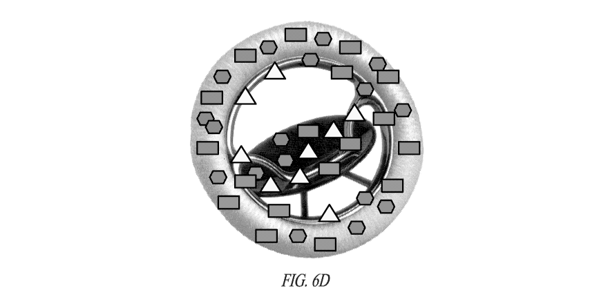
[0004] The heart valves (see Figure 2) are flaps of tissue (leaflets)
that open
and close, thereby ensuring that blood flows in one direction. However, heart
valves
can have congenital complications from birth (e.g., due to stenosis or
thickening of the
valve; due to misshapen or malformed leaflets; or due to atresia ¨ or failure
of the valve
orifice to develop), or from disease or trauma that narrows or obstructs flow
through the
valve (e.g., due to stenosis, calcification, infection, or disease). An
additional form of
valvular heart disease occurs when valves do not close properly (or
incompletely)
leading to the backflow of blood into the chamber from which the blood was
originally
pumped (a process referred to as regurgitation, insufficiency, or prolapse).
Mitral valve
regurgitation has a prevalence of about 2% of the population, and is one of
the two most
common valve diseases in the elderly.
CA 02990816 2017-12-22
WO 2015/200707
PCT/US2015/037810
2
[0005] Repair of damaged and ineffective heart valves is typically
accomplished by replacing the defective native valve with replacement valves,
utilizing
either tissue-based (biological) valves (which are mostly commonly obtained
from pigs)
and mechanical or artificial heart valves. While these valves have
revolutionized
surgical procedures and patient outcomes, they are still subject to a large
number of
complications.
[0006] For example, mechanical heart valve can suffer problems of wear
and
durability, blockage (from clot, infectious "vegetations"), can cause
cavitation
(formation of microbubbles), result in red blood cell damage, require the
patient to be
on anticoagulation therapy for life, and be prone to infection. Tissue-based
valves can
similarly wear or fatigue over time, become blocked (fibrous tissue,
calcifications, clot,
vegetations), and/or become infected.
[0007] The present invention discloses novel heart valves, as well as
related
delivery devices which overcome many of the difficulties of previous heart
valve-like
devices, methods for constructing and monitoring these novel devices, and
further
provides other related advantages.
SUMMARY
[0008] Briefly stated, heart valves having sensors, as well as related
delivery
devices are provided with a number of sensors to monitor the integrity and
efficaciousness of the device.
[0009] Within one embodiment, sensors can be positioned within the
heart
valve, and/or on one or more surfaces of the heart valve. When the phrase
"placed in a
heart valve" is utilized, it should be understood to refer to any of the above
embodiments, unless the context of the usage implies otherwise. Within certain
embodiments, the sensors are of the type that are passive and thus do not
require their
own power supply.
[0010] A wide variety of sensors can be utilized within the present
invention,
including for example, fluid pressure sensors, contact sensors, position
sensors,
accelerometers, vibration sensors, pulse pressure sensors, liquid (e.g.,
blood) volume
sensors, liquid (e.g., blood) flow sensors, liquid (e.g., blood) chemistry
sensors, liquid
(e.g., blood) metabolic sensors, mechanical stress sensors, and temperature
sensors.
Within one embodiment the sensor can be connected with other medical devices
that
CA 02990816 2017-12-22
WO 2015/200707
PCT/US2015/037810
3
can be utilized to delivery one or more drugs. Within other embodiments the
one or
more sensors can be a wireless sensor, and / or a sensor that is connected to
a wireless
microprocessor.
[0011] Within particularly preferred embodiments, a plurality of
sensors are
positioned on the heart valve, and within yet other embodiments more than one
type of
sensor is positioned on the device. Within other related embodiments the
plurality of
sensors are positioned on or within the device at a density of greater than 1,
2, 3, 4, 5, 6,
7, 8, 9, 10 or 20 sensors per square centimeter. Within other embodiments the
plurality
of sensors are positioned on or within the device at a density of greater than
1, 2, 3, 4, 5,
6, 7, 8, 9. 10 or 20 sensors per cubic centimeter. Within either of these
embodiments
there can be less than 50, 75, 100, or 200 sensors per square centimeter, or
per cubic
centimeter.
[0012] Within other embodiments of the invention each assembly has a
unique
device identification number. Within further embodiments one or more (or each)
of the
sensors have a unique sensor identification number. Within yet other
embodiments, one
or more (or each) of the sensors is uniquely defined within a specific
position on or
within the device.
[0013] According to various embodiments, sensors are placed at
different
locations in a heart valve in order to monitor the operation, movement,
medical imaging
(both of the heart valve and associated delivery device, if any, and the
surrounding
tissues), function, wear, performance, potential side effects, medical status
of the patient
and the medical status of the heart valve and its interface with the live
tissue of the
patient. Live, continuous, in situ, monitoring of patient activity, patient
function,
cardiac function, device activity, device function, performance, placement,
surface
characteristics (flow and chemical content of fluids moving over or through a
surface of
the device); presence of inflammatory tissues, bacteria or biofilm on the
surface etc.),
device forces and mechanical stresses, device and surrounding tissue anatomy
(imaging), mechanical and physical integrity of the heart valve, and potential
side
effects is provided. In addition, information is available on many aspects of
the device
and its interaction with the patient's own body tissues, including clinically
important
measurements not currently available through physical examination, medical
imaging
and diagnostic medical studies.
CA 02990816 2017-12-22
WO 2015/200707
PCT/US2015/037810
4
[0014] According to one embodiment, the sensors provide evaluation
data of
any motion, movement and/or migration of the heart valve during and after
placement.
Motion sensors and accelerometers can be used to accurately determine the
movement
of the medical device during physical examination and during normal daily
activities
between visits. Motion sensors and accelerometers can be used to accurately
determine
the movement valve leaflets (discs or balls) in situ in order to determine
function,
degree of closing and the potential for regurgitation. Motion sensors and
accelerometers
can also be used to accurately determine the movement of the heart valve
during
placement by the physician.
[0015] According to another embodiment, contact sensors are provided
between the heart valve and the surrounding tissue and between the moving
components (such as leaflets, discs, and balls) of the heart valve. In other
embodiments, vibration sensors are provided to detect the vibration between
the
medical device and the surrounding tissue. In other embodiments, strain gauges
are
provided to detect the strain between a heart valve and the surrounding
tissue. Sudden
increases in strain may indicate that too much stress is being placed on the
heart valve,
which may increase damage to the surrounding body tissues or even result in
perforation of the tissues that are being instrumented.
[0016] According to other embodiments, accelerometers are provided
which
detect vibration, shock, tilt and rotation. According to other embodiments,
sensors for
measuring surface wear, such as contact or pressure sensors, may be embedded
at
different depths within the heart valve in order to monitor contact of the
heart valve
with vessel walls, or degradation of the heart valve components over time. In
other
embodiments, position sensors, as well as other types of sensors, are provided
which
indicate movement or migration of the medical device in actual use over a
period of
time.
[0017] According to other embodiments, fluid pressure sensors, pulse
pressure
sensors, liquid (e.g., blood) volume sensors, liquid (e.g., blood) flow
sensors, liquid
(e.g., blood) chemistry sensors, liquid (e.g., blood) metabolic sensors,
contact sensors,
and temperature sensors are provided which can monitor the surface environment
of the
heart valve in situ. Important changes to the surface such as clotting,
obstruction,
inflammatory tissue (fibrosis), stenosis, infection (bacteria, fungus, pus,
white blood
cells, biofilm, etc.), narrowing, increased pressure and changes in flow rates
through the
CA 02990816 2017-12-22
WO 2015/200707
PCT/US2015/037810
heart valve can be identified in this manner. Also of great value in the
continuous
monitoring of patient function, status and health are changes in the content
(for
example: protein, albumin; white cell counts, red cell counts, PT, PTT,
hematocrit,
bacteria) and/or chemistry (for example: glucose, calcium, magnesium,
electrolytes,
phosphate, hemoglobin, ketones, bilirubin, creatinine, blood urea nitrogen,
pH, liver
enzymes, cardiac enzymes, blood lipids, oxygen levels, therapeutic and illicit
drug
levels, etc).
[0018] According to other embodiments, blood flow rate detectors,
blood
pressure detectors, and blood volume detectors (e.g., to measure blood volume
over a
unit of time) located on and within implanted artificial heart valves can
measure
systolic and diastolic pressure, and estimate systemic vascular resistance and
pulmonary
vascular resistance. These sensor readings can also be utilized to calculate
cardiac
output, ejection fraction and cardiac index (key clinical measurements that
are valuable
in monitoring cardiac-compromised patients, which many valvular patients are).
[0019] Within further embodiments, the heart valve can contain sensors
at
specified densities in specific locations. For example, the heart valve can
have a
density of sensors of greater than one, two, three, four, five, six, seven,
eight, nine, or
ten sensors (e.g., accelerometers (acceleration, tilt, vibration, shock and
rotation
sensors), pressure sensors, contact sensors, flow sensors, position sensors,
blood
chemistry sensors, blood metabolic sensors, mechanical stress sensors and
temperature
sensors, or any combination of these) per square centimeter of the device.
Within other
embodiments, the heart valve can have a density of sensors of greater than
one, two,
three, four, five, six, seven, eight, nine, or ten sensors [e.g.,
accelerometers
(acceleration, tilt, vibration, shock and rotation sensors)1, pressure
sensors, flow
sensors, contact sensors, position sensors, blood chemistry sensors, blood
metabolic
sensors, mechanical stress sensors and temperature sensors, or any combination
of
these) per cubic centimeter of the device.
[0020] Within certain embodiments of the invention, the heart valve is
provided with a specific unique identifying number, and within further
embodiments,
each of the sensors on, in or around the heart valve each have either a
specific unique
identification number, or a group identification number (e.g., an
identification number
that identifies the sensor as accelerometers (acceleration, tilt, vibration,
shock and
rotation sensors), pressure sensors, flow, sensors, contact sensors, position
sensors,
CA 02990816 2017-12-22
WO 2015/200707
PCT/US2015/037810
6
blood chemistry sensors, blood metabolic sensors, mechanical stress sensors
and
temperature sensors). Within yet further embodiments, the specific unique
identification number or group identification number is specifically
associated with a
position on, in or around the heart valve.
[0021] Within other aspects of the invention methods are provided for
monitoring an implanted heart valve or device comprising the steps of
transmitting a
wireless electrical signal from a location outside the body to a location
inside the body;
receiving the signal at a sensor positioned on, in or around an heart valve or
device
(and/or delivery device such as a guidewire, catheter or balloon) located
inside the
body; powering the sensor using the received signal; sensing data at the
sensor; and
outputting the sensed data from the sensor to a receiving unit located outside
of the
body.
[0022] Within other aspects of the invention methods are provided for
imaging
a heart valve or device as provided herein, comprising the steps of (a)
detecting the
location of one or more sensors in a heart valve and/or associated heart valve
device
(e.g. a delivery device such as a guidewire, catheter or balloon); and (b)
visually
displaying the location of said one or more sensors, such that an image of the
heart
valve or delivery device is created. Within various embodiments, the step of
detecting
may be done over time, and the visual display may thus show positional
movement over
time. Within certain preferred embodiments the image which is displayed is a
three-
dimensional image.
[0023] The imaging techniques provided herein may be utilized for a
wide
variety of purposes. For example, within one aspect, the imaging techniques
may be
utilized during an open surgical procedure or a percutaneous implantation
procedure in
order to ensure proper placement and working of the heart valve. Within other
embodiments, the imaging techniques may be utilized post-operatively in order
to
examine the heart valve, and/or to compare operation and/or movement
(migration) of
the device over time.
[0024] The integrity of the heart valve can be wirelessly interrogated
and the
results reported on a regular basis. This permits the health of the patient to
be checked
on a regular basis or at any time as desired by the patient and/or physician.
Furthermore, the heart can be wirelessly interrogated when signaled by the
patient to do
so (via an external signaling/triggering device) as part of "event recording"
¨ i.e. when
CA 02990816 2017-12-22
WO 2015/200707
PCT/US2015/037810
7
the patient experiences a particular event (e.g. chest pain, shortness of
breath, syncope,
etc.) she/he signals/triggers the device to obtain a simultaneous reading in
order to
allow the comparison of subjective/symptomatic data to objective/sensor data.
Matching event recording data with sensor data can be used as part of an
effort to better
understand the underlying cause or specific triggers of a patient's particular
symptoms.
Hence, within various embodiments of the invention methods are provided for
detecting
and/or recording an event in a subject with one of the heart valve and/or
delivery
devices provided herein, comprising the interrogating at a desired point in
time. Within
one aspect of the invention, methods are provided for detecting and/or
recording an
event in a subject with a heart valve and/or delivery device as provided
herein,
comprising the step of interrogating at a desired point in time the activity
of one or
more sensors within the heart valve and/or delivery device, and recording said
activity.
Within various embodiments, they may be accomplished by the subject and/or by
a
health care professional (during and after implantation). Within related
embodiments,
the step of recording may be performed with one or more wired devices, or,
wireless
devices that can be carried, or worn (e.g., a cellphone, watch or wristband,
and/or
glasses).
[0025] Within further embodiments, each of the sensors contains a
signal-
receiving circuit and a signal output circuit. The signal-receiving circuit
receives an
interrogation signal that includes both power and data collection request
components.
Using the power from the interrogation signal, the sensor powers up the parts
of the
circuitry needed to conduct the sensing, carries out the sensing, and then
outputs the
data to the interrogation module. The interrogation module acts under control
of a
control unit which contains the appropriate I/O circuitry, memory, a
controller in the
form of a microprocessor, and other circuitry in order to drive the
interrogation module.
Within yet other embodiments the sensor [e.g., accelerometers (acceleration,
tilt,
vibration, shock and rotation sensors), pressure sensors, flow sensors,
contact sensors,
position sensors, blood chemistry sensors, blood metabolic sensors, mechanical
stress
sensors and temperature sensors) are constructed such that they may readily be
incorporated into or otherwise mechanically attached to the heart valve or
device (e.g.,
by way of a an opening or other appendage that provides permanent attachment
of the
sensor to the heart valve) and/or readily incorporated into body of the heart
valve or
delivery device.
CA 02990816 2017-12-22
WO 2015/200707
PCT/US2015/037810
8
[0026] Within yet other aspects of the invention, methods and devices
are
provided suitable for transmitting a wireless electrical signal from a
location outside the
body to a location inside the body; receiving the signal at one of the
aforementioned
sensors positioned on, in or around a heart valve located inside the body;
powering the
sensor using the received signal; sensing data at the sensor; and outputting
the sensed
data from the sensor to a receiving unit located outside of the body. Within
certain
embodiments the receiving unit can provide an analysis of the signal provided
by the
sensor.
[0027] The data collected by the sensors can be stored in a memory
located
within the heart valve, or on an associated device (e.g., an external device
such as a
cellphone, watch, wristband, and/or glasses. During a visit to the physician,
the data
can be downloaded via a wireless sensor, and the doctor is able to obtain data
representative of real-time performance of the heart valve and any associated
medical
device.
[0028] The advantages obtained include more accurate monitoring of the
heart
valve or device and permitting medical reporting of accurate, in situ, data
that will
contribute to the health of the patient. The details of one or more
embodiments are set
forth in the description below. Other features, objects and advantages will be
apparent
from the description, the drawings, and the claims. In addition, the
disclosures of all
patents and patent applications referenced herein are incorporated by
reference in their
entirety.
BRIEF DESCRIPTION OF THE DRAWINGS
[0029] Figure 1 illustrates a normal heart as well as the location of
various
anatomical structures including the 4 heart valves.
[0030] Figure 2 illustrates the valves of a normal heart depicted in
their closed
position.
[0031] Figure 3 illustrates several representative mechanical heart
valves based
upon a "caged ball" design. Figure 3A illustrates one example with a
restraining cage,
occluder ball, and a suture ring. Figure 3B illustrates a Starr-Edwards valve.
Figure 3C
illustrates another version of a Starr-Edwards valve. Figure 3D illustrates a
Smeloff-
Cutter valve.
CA 02990816 2017-12-22
WO 2015/200707
PCT/US2015/037810
9
[0032] Figure 4 illustrates a representative 'tilting disc' mechanical
valve and
depicts the occluding disc and flange, inlet strut and 2 outlet struts, and
the suture ring.
[0033] Figure 5 represents several illustrative bileaflet or
trileaflet mechanical
valves. Figure 5A illustrates a representative bileaflet valve, and depicts
the 2 leaflets,
leaflet hinges, and the suture ring. Figure 5B illustrates how blood flows
through a
trileaflet mechanical valve. Figure 5C and 5D illustrate modelling of the
valve, and
illustrate how a trileaflet mechanical valve opens.
[0034] Figure 6A illustrates a representative bileaflet mechanical
valve with
sensors. Figure 6B illustrates a tilting disc mechanical valve with sensors.
Figure 6C
illustrates a representative bileaflet mechanical valve with sensors. Figure
6D
illustrates a representative tilting disc mechanical valve with sensors.
[0035] Figure 7A illustrates a representative tissue (biological)
porcine valve.
Figure 7B illustrates a representative tissue (biological) valve made from
bovine
pericardium.
[0036] Figure 8A illustrates a representative porcine valve with a
variety of
sensors. Figure 8B illustrates a representative bovine valve with a variety of
sensors.
Figure 8C illustrates a representative porcine valve with a variety of
sensors. Figure 8D
illustrates a representative bovine valve with a variety of sensors.
[0037] Figure 9 illustrates a variety of percutaneous heart valves,
including: an
expanded scaffold (self-expanding stent) for a heart valve (Figure 9A); the
expansion of
a self-expanding percutaneous heart valve (Figure 9B) as it is released from
its delivery
catheter; and a percutaneous heart valve being expanded in situ (Figure 9C) in
the aortic
valve.
[0038] Figures 10A, 10B and 10C illustrate a self-expanding
percutaneous
heart valve with a variety of sensors. Figure 10A illustrates sensors on the
expanded
(stent) scaffold, Figure 10B illustrates sensors on the valvular cusps in the
closed
position, and Figure 10C illustrates sensors on both the stent scaffold and
the valvular
components.
[0039] Figure 11 illustrates a representative percutaneous heart valve
with
sensors on a representative delivery system with sensors.
[0040] Figure 12 illustrates several embodiments of a balloon-
expandable
percutaneous heart artificial valve, including: Figure 12A and 12B, a
diagrammatic
illustration of a balloon-expandable percutaneous heart valve; Figure 12C
illustrates
CA 02990816 2017-12-22
WO 2015/200707
PCT/US2015/037810
expansion of a percutaneous heart valve on a balloon catheter delivery device;
Figure
12D illustrates an expanded SAPIEN XT heart valve from Edwards Lifesciences;
Figures 12E (delivery of the device via the apex of the heart ¨ through the
chest wall)
and 12F (delivery of the device via the vasculature ¨ advancing the catheter
into the
aorta) illustrate two different delivery approaches for a balloon-expandable
percutaneous heart valve.
[0041] Figures 13A (valvular cusps), 13B (supporting stent) and 13C
(both
valvular cusps and supporting stent) illustrate a variety of sensors on a
balloon-
expandable percutaneous heart valve.
[0042] Figure 14A illustrates a variety of sensors on a balloon
delivery device
for a balloon-expandable percutaneous heart valve, as well as a variety of
sensors on the
balloon itself. Figure 14B illustrates a variety of sensors on a balloon-
expandable
percutaneous heart valve.
[0043] Figure 15 illustrates an information and communication
technology
system embodiment arranged to process sensor data.
[0044] Figure 16 is a block diagram of a sensor, interrogation module,
and a
control unit according to one embodiment of the invention.
[0045] Figure 17 is a schematic illustration of one or more sensors
positioned
on a heart valve within a subject which is being probed for data and
outputting data,
according to one embodiment of the invention.
DETAILED DESCRIPTION OF THE INVENTION
[0046] Briefly stated the present invention provides a variety of
heart valves
that can be utilized to monitor the placement, performance, integrity and/or
efficaciousness of the artificial heart valve, and any associated medical
device (e.g., a
delivery device such as a catheter, balloon or guidewire). Prior to setting
forth the
invention however, it may be helpful to an understanding thereof to first set
forth
definitions of certain terms that are used hereinafter.
[0047] "Heart valve" refers to a device which can be implanted into
the heart
of a patient with valvular disease. There are three principle types of heart
valves:
mechanical, biological, and tissue-engineered (although, for purposes of this
disclosure
tissue-engineered valves will be considered along with other biological
valves).
Mechanical valves typically fall into two categories: 1) heart valves for
surgical
CA 02990816 2017-12-22
WO 2015/200707
PCT/US2015/037810
11
procedures utilizing a sternotomy or "open heart" procedure (e.g., 'caged
ball', 'tilting
disc', bileaflet and trileaflet designs); and 2) heart valves which are
percutaneously
implanted [e.g., either a stent framed (self-expanding stent or balloon-
expandable stent)
or non-stent framed design] that can often contain valve cusps which are
fabricated
from biological sources (bovine or porcine pericardium). Tissue-based or
'biological'
valves are typically made from either porcine or bovine sources, and are
typically
prepared either from the valve of the animal (e.g., a porcine valve), or from
tissue of the
pericardial sac (e.g., a bovine pericardial valve or a porcine pericardial
valve). Tissue-
engineered valves are valves that have been artificially created on a scaffold
(e.g.,
through the growth of suitable cells on a tissue scaffold). Tissue-engineered
valves
have not yet been commercially adopted.
[0048] In addition to heart valves, delivery devices are also
provided. In the
context of percutaneous delivery, particularly preferred delivery devices
comprise a
guidewire, delivery catheter (see., e.g., Figures 9B, 11 and 12C), catheters
with a
"sheath" that deploy self-expanding devices (see., e.g., Figures 9b and 11),
catheters
with an expandable balloon (see., e.g., Figure 12C), and anchoring suture
devices.
Utilizing such devices and methods heart valves can be replaced without the
need for
open heart surgery.
[0049] Representative examples of heart valves and associated delivery
devices
are described in U.S. Patent Nos. 6,564,805, 6,730,122, 7,033,090, 7,578,842,
8,142,497, 8,287,591, and 8,568,474; U.S. Publication Nos. 2010/0076548,
2010/0161046, 2010/117471, 2011/0009818, 2011/0190897, 2012/0179243,
2013/0096671, 2013/0166023, 2013/0268066; and PCT Publication Nos. WO
2012/011108, and WO 2013/021374; all of the above of which are incorporated by
reference in their entirety.
[0050] The present invention provides heart valves and related
delivery
devices, all of which have sensors as described in further detail below. The
heart valve
and related delivery devices are preferably sterile, non-pyrogenic, and/or
suitable for
use and/or implantation into humans. However, within certain embodiments of
the
invention the heart valve and/or delivery device can be made in a non-
sterilized
environment (or even customized or "printed" for an individual subject), and
sterilized
at a later point in time.
CA 02990816 2017-12-22
WO 2015/200707
PCT/US2015/037810
12
[0051] "Sensor" refers to a device that can be utilized to measure one
or more
different aspects of a body, body fluid, and/or of a heart valve and/or
associated
delivery device. Representative examples of sensors suitable for use within
the present
invention include, for example, fluid pressure sensors, contact sensors,
position sensors,
pulse pressure sensors, liquid (e.g., blood) volume sensors, liquid (e.g.,
blood) flow
sensors, chemistry sensors (e.g., for blood and/or other fluids), metabolic
sensors (e.g.,
for blood and/or other fluids), accelerometers, mechanical stress sensors and
temperature sensors. Within certain embodiments the sensor can be a wireless
sensor,
or, within other embodiments, a sensor connected to a wireless microprocessor.
Within
further embodiments one or more (including all) of the sensors can have a
Unique
Sensor Identification number ("USI") which specifically identifies the sensor.
[0052] A wide variety of sensors (also referred to as
Microelectromechanical
Systems or "MEMS", or Nanoelectromechanical Systems or "NEMS", and BioMEMS
or BioNEMS, see generally https://en.wikipedia.org/wiki/MEMS) can be utilized
within
the present invention. Representative patents and patent applications include
U.S.
Patent Nos. 7,383,071 and 8,634,928, and U.S. Publication Nos. 2010/0285082,
and
2013/0215979. Representative publications include "Introduction to BioMEMS" by
Albert Foch, CRC Press, 2013; "From MEMS to Bio-MEMS and Bio-NEMS:
Manufacturing Techniques and Applications by Marc J. Madou, CRC Press 2011;
"Bio-
MEMS: Science and Engineering Perspectives, by Simona Badilescu, CRC Press
2011;
"Fundamentals of BioMEMS and Medical Microdevices" by Steven S. Saliterman,
SPIE-The International Society of Optical Engineering, 2006; "Bio-MEMS:
Technologies and Applications", edited by Wanjun Wang and Steven A. Soper, CRC
Press, 2012; and "Inertial MEMS: Principles and Practice" by Volker Kempe,
Cambridge University Press, 2011; Polla, D. L., et al., "Microdevices in
Medicine,"
Ann. Rev. Biomed. Eng. 2000, 02:551-576; Yun, K. S., et al., "A Surface-
Tension
Driven Micropump for Low-voltage and Low-Power Operations," J.
Microelectromechanical Sys., 11:5, October 2002, 454-461; Yeh, R., et al.,
"Single
Mask, Large Force, and Large Displacement Electrostatic Linear Inchworm
Motors," J.
Microelectromechanical Sys., 11:4, August 2002, 330-336; and Loh, N. C., et
al., "Sub-
cm3Interferometric Accelerometer with Nano-g Resolution," J.
Microelectromechanical Sys., 11:3, June 2002, 182-187; all of the above of
which are
incorporated by reference in their entirety.
CA 02990816 2017-12-22
WO 2015/200707
PCT/US2015/037810
13
[0053] Within various embodiments of the invention the sensors
described
herein may be placed at a variety of locations and in a variety of
configurations, on the
inside of the heart valve and/or delivery device, within the body of the heart
valve
and/or delivery device, on the outer surface (or surfaces) of the heart valve
and/or
delivery device, and/or between the heart valve and any delivery device (e.g.,
a balloon
catheter). Within certain embodiments the heart valve and/or delivery device
has
sensors at a density of greater than 1, 2, 3, 4, 5, 6, 7, 8, 9, 10 or greater
than 10 sensors
per square centimeter. Within other aspects the heart valve and/or delivery
device has
sensors at a density of greater than 1, 2, 3, 4, 5, 6, 7, 8, 9, 10 or greater
than 10 sensors
per cubic centimeter. Within either of these embodiments there can be less
than 50, 75,
100, or 100 sensors per square centimeter, or per cubic centimeter. Within
various
embodiments the at least one or more of the sensors may be placed randomly, or
at one
or more specific locations within the heart valve, delivery devices, or kit as
described
herein.
[0054] In various embodiments, the sensors may be placed within
specific
locations and/or randomly throughout the heart valve or delivery devices,
associated
medical device (e.g., guidewire or delivery instrument) or kit. In addition,
the sensors
may be placed in specific patterns (e.g., they may be arranged in the pattern
of an X, as
oval or concentric rings around the heart valve, associated medical device
(e.g.,
guidewire, catheter, balloon catheter, anchoring suture, or delivery
instrument) or kit.
REPRESENTATIVE EMBODIMENTS OF HEART VALVES AND MEDICAL USES OF SENSOR
CONTAINING HEART VALVES
[0055] In order to further understand the various aspects of the
invention
provided herein, the following sections are provided below: A. Heart valves
and their
Use; B. Use of Heart valves to Deliver Therapeutic Agent(s); C. Use of Heart
valves
having Sensors to Measure Flow and Flow Obstruction; D. Methods for Monitoring
Infection in Heart valves; E. Further Uses of Sensor-containing Heart valves
in
Healthcare; F. Generation of Power from Heart valves; G. Medical Imaging and
Self-
Diagnosis of Assemblies Comprising Heart valves, Predictive Analysis and
Predictive
Maintenance; H. Methods of Monitoring Assemblies Comprising Heart valves; and
I.
Collection, Transmission, Analysis, and Distribution of Data from Assemblies
Comprising Heart valves.
CA 02990816 2017-12-22
WO 2015/200707 PCT/US2015/037810
14
A. Heart valves and their Use
Al. Mechanical Heart valves and their Use
A1.1 'Open Heart' Surgery Heart Valves: "Caged Ball", "Tilting
Disc", and Bi and Tr-Leaflet Designs
[0056] As noted above, within various embodiments of the invention
mechanical heart valves are provided with a variety of the sensors described
herein.
For example, Figure 3 illustrates several representative mechanical heart
valves based
upon a "caged ball" design [e.g., as shown in Figure 3A such devices have a
restraining
cage (typically made of metal), an occluder ball (typically made from a
silicone
elastomer), and a suture ring]. Representative examples include the Starr-
Edwards
valve as shown in Figures 3B and 3C, and the Smeloff-Cutter valve as shown in
Figure
3D. Figure 4 illustrates a representative "tilting disc" heart valve, showing
the various
components of the device. Typically there is an occluder disc that rotates on
a flange
and 2 metal struts (an inlet and an outlet strut) which stop the occluder disc
in either the
open or the closed position; additionally, there is a metal ring covered by
ePTFE that is
used as a suture ring to anchor the valve in place. Figure 5 illustrates
several bileaflet
or trileaflet valves. Figure 5A illustrates a representative bileaflet valve,
and depicts the
two leaflets, leaflet hinges, and the anchoring suture ring. Figure 5B
illustrates how
blood flows through a trileaflet valve. Figure 5C and 5D illustrate modelling
of the
valve, as well as illustrating how the leaflets open.
[0057] Mechanical valves have improved greatly since their introduction,
yet
they still suffer from numerous complications. For example, the caged-ball
design can
last for a long time, but require a lifetime of anticoagulation for the
patient. Red blood
cells and platelets get damaged flowing through the mechanical valves which
can lead
to a hypercoagulative state that can result in thrombus and embolis formation
(necessitating blood thinner therapy) and can even result in anemia. The
leaflet
(bileaflet and trileaflet) mechanical valves cause less damage to blood cells
(and are
less thrombogenic and require lower levels of anticoagulation therapy), but
they are
vulnerable to backflow, and do not last as long. Mechanical valves are also
subject to
impact wear (occurs in the hinges of bileaflet valves, between the occluder
and ring in
tilting disc valves, and between the ball and cage in ball-cage valves) and
frictional
wear (occurs between the occluder and the struts in tilting disc valves and
between the
leaflet pivots and hinge cavities in bileaflet valves), and can cause
'cavitation' (i.e., the
CA 02990816 2017-12-22
WO 2015/200707
PCT/US2015/037810
formation of microbubbles, which can erode the valve surface, increase blood
cell
damage and increase the incidence of thromboembolic events).
[0058] Hence, the present invention provides mechanical heart valves
which
have one or more sensors, including for example, fluid pressure sensors,
contact
sensors, accelerometers, vibration sensors, pulse sensors, liquid (e.g.,
blood) volume
sensors, liquid (e.g., blood) flow sensors, liquid (e.g., blood) chemistry
sensors, liquid
(e.g., blood) metabolic sensors, mechanical stress sensors, and temperature
sensors.
Such sensors can be placed on, in, or within the various components of the
heart valve,
and can be utilized to monitor, amongst other things, thrombogenesis, wear,
blockage,
sticking (impaired movement of the `valve'), trans-valvular pressure gradients
(an
indicator of the potential for cavitation), leakage (backflow or
regurgitation),
detachment of the suture ring (from, for example, suture breakage), assembly
of the
device (where possible), correct anatomical placement of the device, failure,
and safety.
[0059] For example, as shown in Figure 6A, 6B, 6C and 6D, mechanical
valves
are illustrated with a variety of sensors. Within one embodiment blood flow
(motion)
sensors are provided on a mechanical heart valve (e.g., 'caged-ball', 'tilting
disc', bi or
tri-leaflet valves). The sensors can be provided in specific locations, or
diffusively
throughout the device. For example, for the tilting disc mechanical valve,
sensors can
be concentrated on the occluder disc (both sides), as well as on the inlet and
outlet
struts, flange and suture ring. For the bileaflet (or trileaflet) designs, the
sensors can be
concentrated on the leaflets (both sides), as well as on the flange and suture
ring. For
the 'caged-ball' design, the sensors can be concentrated on the ball and cage,
as well as
on the suture ring.
[0060] Blood flow sensors can be utilized to measure fluid flow
through the
mechanical valve, and to detect abnormalities that occur acutely, or gradually
over time.
For example, a decrease in forward flow may suggest the development of a
stenosis
[from thrombus formation, infection (biofilm or vegetations)1, sticking of
moving
components (the ball, disc, or leaflets), or failure of the device. Increases
in backwards
flow can be suggestive of regurgitation, due to sticking, thrombus, infection
or failure
of the moving components. Blood flow sensors can show real-time movement of
blood
through the valve, and permit hemodynamic monitoring and determination of
cardiac
output (similar to an echocardiogram), ejection fraction and cardiac index
(key clinical
CA 02990816 2017-12-22
WO 2015/200707
PCT/US2015/037810
16
measurements that are valuable in monitoring cardiac-compromised patients,
which
many valvular patients are).
[0061] Within other embodiments, pressure sensors can be utilized to
measure
pressure on both sides of the valve, and to detect abnormalities that occur
acutely, or
gradually over time. For example, an increased pressure gradient can indicate
a risk of
cavitation. A low pressure gradient can indicate regurgitation and/or possible
failure.
Pressure sensors on the ventricular side of a valve can measure systolic and
diastolic
pressure, and estimate systemic vascular resistance and pulmonary vascular
resistance
(depending upon the valve). These sensor readings can also be utilized to
calculate
cardiac output, ejection fraction and cardiac index and permit in situ
hemodynamic
monitoring.
[0062] Within further embodiments blood volume sensors can be utilized
to
measure fluid flow through the valve, and to detect abnormalities that occur
acutely, or
gradually over time. For example, a decrease in forward blood volume may
suggest the
development of a stenosis [from thrombus formation, infection (biofilm or
vegetations)1, sticking of moving components (the ball, disc, or leaflets), or
failure of
the device. Increases in backwards blood volume (> 5 ml) can be suggestive of
regurgitation, due to sticking, thrombus, infection or failure of the moving
components.
Blood volume sensors (e.g., to measure blood volume over a unit of time) can
show
real-time movement of blood through the valve, and permit hemodynamic
monitoring
and determination of cardiac output (similar to an echocardiogram), ejection
fraction
and cardiac index and permit in situ hemodynamic monitoring.
[0063] Within yet other embodiments metabolic (or chemical) sensors on
mechanical valves can be utilized to measure metabolic parameters important in
vascular function. Representative examples include coagulation/clotting
parameters
such as PT, PTT, clotting time and INR; Blood Oxygen content; Blood CO2
content;
Blood pH; Blood cholesterol; Blood lipids (HDL, LDL); Blood Glucose; Cardiac
enzymes; Hepatic Enzymes; Electrolytes; Blood Cell Counts; and Kidney Function
parameters (BUN, Creatinine, etc.).
[0064] Within other embodiments, position sensors are provided that
can be
utilized to measure the location of fixed and moving components of the
mechanical
valve. For example, gaps in the leaflets, occlude disc/ring and cage/ball are
suggestive
of leakage and regurgitation. Position sensors can also be utilized to 'image'
valvular
CA 02990816 2017-12-22
WO 2015/200707
PCT/US2015/037810
17
motion (opening, closing, and integrity of the seal). Changes in position
sensors on the
suture ring can show slippage, migration, failure, and suture breakage.
Dilation of the
ring can indicate possible dilative cardiomyopathy, whereas narrowing of the
ring can
indicate myocardial hypertrophy.
[0065] Within further embodiments contact sensors are provided that
can be
utilized to measure the contact between fixed and moving components of a
mechanical
valve. For example, incomplete contact between the leaflets, between the
occlude disc
and the ring, and between the ball and cage are suggestive of leakage and
regurgitation.
Contact sensors can also be utilized to 'image' valvular motion (opening,
closing, and
integrity of the seal). Changes in contact sensors on the suture ring can show
slippage,
migration, failure, and suture breakage. Contact sensors can also be utilized
to monitor
the surface of the valve (e.g., to detect the presence of surface anomalies
such as the
formation of clot or thombi, biofilm or vegetations on the valve surface), and
to monitor
for friction wear, impact wear, and breakage (e.g., contact sensors can be
placed at
various depths of any of the various components (e.g., occluder disc, strut,
occluder
ring, leaflets, leaflet pivots, hinges, ball and/or cage).
[0066] Accelerometers can be utilized to measure the location and
movement
of fixed and moving components of a mechanical valve. For example, gaps in the
leaflets, occlude disc and ring, and ball and cage are suggestive of leakage
and
regurgitation. Accelerometers can also be utilized to 'image' real time
valvular motion
(opening, closing, and integrity of the seal), and to image changes that might
occur in
the mechanical valve over time. Changes in accelerometers on the suture ring
can show
slippage, migration, failure, and suture breakage.
A1.2 Biological (tissue-based) Heart Valves and their Use
[0067] As noted above, within various embodiments of the invention
biological
(tissue-based) heart valves are provided with a variety of sensors described
herein.
Briefly, biological valves are heart valves that are typically designed from
xenographic
(i.e., from a different species) tissue. Most typically, biological heart
valves are
constructed from porcine or bovine (usually either valvular or pericardial)
tissue,
although other animal tissues (e.g., equine) have also been utilized.
Representative
examples of biological heart valves are provided in Figure 7A (an illustration
of a
CA 02990816 2017-12-22
WO 2015/200707
PCT/US2015/037810
18
porcine valve), and Figure 7B (an illustration of a valve made from bovine
pericardium).
[0068] For purposes of this disclosure, tissue-engineered valves can
also be
considered to be a biological valve. Briefly, tissue-engineered valves
generally
comprise a layer of cells (e.g., fibroblasts, stem cells, or some combination
of cells),
that are grown over a tissue scaffold (typically a synthetic polymer-based
scaffold, see
generally Lichtenberg et al., 'Biological scaffolds for heart valve tissue
engineering",
Methods Mol. Med. 2007; 140:309-17; see also U.S. Pub. No. 2010/117471).
[0069] Biological valves have a number of advantages in that they do
not
damage red blood cells or platelets (and therefore do not require
anticoagulation
therapy) and they do not cause cavitation to the same degree as mechanical
valves.
However, they still suffer from several complications, including for example:
1) they
have a more limited lifespan than mechanical valves; 2) they can cause an
immune
reaction; 3) they can clot and form emboli (causing strokes or myocardial
infarction); 4)
they can also become infected and form septic emboli; 5) they can become
covered with
fibrous tissue; and 6) they can become calcified. Common biological valves are
currently made by Edwards Lifesciences, Medtronic, St. Jude, Sorin, 3F
Therapeutics,
CryoLife and LifeNet Health.
[0070] Hence, the present invention provides biological heart valves
which
have one or more sensors, including for example, fluid pressure sensors,
contact
sensors, accelerometers, vibration sensors, pulse sensors, liquid (e.g.,
blood) volume
sensors, liquid (e.g., blood) flow sensors, liquid (e.g., blood) chemistry
sensors, liquid
(e.g., blood) metabolic sensors, biological stress sensors, and temperature
sensors.
Such sensors can be place on, in, or within the various components of the
heart valve,
and can be utilized to monitor, amongst other things, thrombogenesis,
infection
(vegetations), wear, blockage, sticking (impaired movement of the valve
leaflets), trans-
valvular pressure gradients, leakage (backflow or regurgitation), detachment
of the
suture ring (from, for example, suture breakage), correct anatomical placement
of the
device, failure, and safety.
[0071] Figures 8A, 8B, 8C, and 8D schematically illustrate biological
valves
with a variety of sensors. Within one embodiment blood flow (motion) sensors
are
provided on a biological heart valve. The sensors can be provided in specific
locations,
CA 02990816 2017-12-22
WO 2015/200707
PCT/US2015/037810
19
or diffusively throughout the device. For example, sensors can be concentrated
in, on,
and/or within the leaflets, the blood contacting surfaces, and the suture
ring.
[0072] Blood flow sensors can be utilized to measure fluid flow
through the
valve, and to detect abnormalities that occur acutely, or gradually over time.
For
example, a decrease in forward flow may suggest the development of a stenosis
[from
thrombus formation, infection (biofilm or vegetations), fibrosis, or
calcification],
sticking of the leaflets, or failure of the device. Increases in backwards
flow can be
suggestive of regurgitation, due to sticking, thrombus, infection, fibrosis,
calcification
or failure of the moving components. Blood flow sensors can show real-time
movement of blood through the valve, and permit hemodynamic monitoring and
determination of cardiac output (similar to an echocardiogram), ejection
fraction and
cardiac index (key clinical measurements that are valuable in monitoring
cardiac-
compromised patients, which many valvular patients are).
[0073] Within other embodiments, pressure sensors can be utilized to
measure
pressure on both sides of the valve, and to detect abnormalities that occur
acutely, or
gradually over time. For example, an increased pressure gradient can indicate
a risk of
cavitation. A low pressure gradient can indicate regurgitation and/or possible
failure.
Pressure sensors on the ventricular side of a biological valve can measure
systolic and
diastolic pressure, and estimate systemic vascular resistance and pulmonary
vascular
resistance (depending upon the valve). These sensor readings can also be
utilized to
calculate cardiac output, ejection fraction and cardiac index and permit in
situ
hemodynamic monitoring.
[0074] Within further embodiments blood volume sensors can be utilized
to
measure fluid volume through the valve, and to detect abnormalities that occur
acutely,
or gradually over time. For example, a decrease in forward blood volume may
suggest
the development of a stenosis [from thrombus formation, infection (biofilm or
vegetations), fibrosis, calcification], sticking of the leaflets, or failure
of the device.
Increases in backwards blood volume (> 5 ml) can be suggestive of
regurgitation, due
to sticking, thrombus, infection, fibrosis, calcification, or failure of the
moving
components. Blood volume sensors (e.g., to measure blood volume over a unit of
time)
can show real-time movement of blood through the valve, and permit hemodynamic
monitoring and determination of cardiac output (similar to an echocardiogram),
ejection
fraction and cardiac index and permit in situ hemodynamic monitoring.
CA 02990816 2017-12-22
WO 2015/200707
PCT/US2015/037810
[0075] Within yet other embodiments metabolic (or chemical) sensors
can be
utilized to measure metabolic parameters important in vascular function.
Representative examples include: Coagulation/Clotting parameters such as PT,
PTT,
clotting time and INR; Blood Oxygen content; Blood CO2 content; Blood pH;
Blood
cholesterol; Blood lipids (HDL, LDL); Blood Glucose; Cardiac enzymes; Hepatic
Enzymes; Electrolytes; Blood Cell Counts; and Kidney Function parameters (BUN,
Creatinine, etc.).
[0076] Within other embodiments position sensors are provided that can
be
utilized to measure location of fixed and moving components of a biological
valve. For
example, gaps in the leaflets (upon closing of the valve) are suggestive of
leakage and
regurgitation. Position sensors can also be utilized to 'image' valvular
motion
(opening, closing, and integrity of the seal). Changes in position sensors on
the suture
ring can show slippage, migration, failure, and suture breakage. Dilation of
the ring can
indicate possible cardiomyopathy, whereas narrowing of the ring can indicate
myocardial hypertrophy.
[0077] Within further embodiments contact sensors are provided that
can be
utilized to measure location of fixed and moving components. For example, gaps
in the
leaflets (upon closing of the valve) are suggestive of leakage and
regurgitation. Contact
sensors can also be utilized to 'image' valvular motion (opening, closing, and
integrity
of the valvular seal). Changes in contact sensors on the suture ring can show
slippage,
migration, failure, and suture breakage. Contact sensors can also be utilized
to monitor
the surface of the valve (e.g., to detect the presence of surface anomalies
such as the
formation of clot or thombi, biofilm or vegetations, fibrosis or calcification
on the valve
surface), and to monitor for friction wear, impact wear, tears and breakage of
the
leaflets.
[0078] Accelerometers can be utilized to measure the location and
movement
of fixed and moving components of a biological valve. For example, gaps in the
leaflets during valve closure are suggestive of leakage and regurgitation.
Accelerometers can also be utilized to 'image' valvular motion (opening,
closing, and
integrity of the seal), and to image changes that might occur over time.
Changes in
accelerometers on the suture ring can show slippage, migration, failure, and
suture
breakage.
CA 02990816 2017-12-22
WO 2015/200707
PCT/US2015/037810
21
A1.3 Percutaneous Heart Valves and their Use
[0079] Within other aspects of the invention percutaneous heart
valves (and
their associated delivery devices are provided with a variety of sensors
described
herein. Briefly, percutaneous aortic valve replacement (PAVR) or transcatheter
aortic
valve replacement (TAVR) is the replacement of the aortic valve through blood
vessels
or other minimally invasive techniques (thus eliminating a need for 'open-
heart'
surgery). Typically, the heart is accessed through the femoral artery in the
leg, apically
(through the apex of the heart), through the subclavian arteries, or the
aorta. Two
companies have currently approved devices for aortic valve replacement: 1)
COREVALVE (Medtronic); and 2) SAPIEN (Edwards Lifesciences). Other
percutaneous aortic valves, mitral valves and other heart valves are under
development.
[0080] The COREVALVE (Medtronic) is schematically illustrated in
Figure 9.
Briefly, it is composed of a self-expanding nitinol support frame (stent) with
cells in a
diamond design (see Figure 9A). It is fitted with bovein or procine
pericardium shaped
into valve leaflets, and provided along with a 18F delivery catheter (see
Figure 9B and
9C). The SAPIEN (Edwards Lifesciences) is schematically illustrated in Figures
12 A
and B; the SAPIEN XT is depicted in Figure 12D. It is a trileaflet heart valve
constructed of bovine pericardium (see Figure 12B) which is mounted on a
balloon-
expandable stainless steel stent (see Figure 12C).
[0081] Percutaneous heart valve delivery has a number advantages,
including
the fact that they do not require open heart surgery, and hence can be
utilized in high-
risk patients that might not live through such a surgery. However, they still
suffer from
complications, including for example: 1) cardiogenic shock, stroke and/or
death; 2)
perforation of the myocardium; 3) cardiac tamponade; 4) ascending aorta
trauma; 5)
embolism; 6) thrombosis; 7) valve migration; 8) valve regurgitation; and 9) a
variety of
other valve dysfunctions (e.g., breaking or fracturing of the valve frame,
incomplete
expansion, bending, build-up of minerals (calcification) or clots
(thrombosis), wear and
tear, pannus (fibrous tissue) formation that might block the valve, and
failures during
the surgical procedure (e.g., to properly size and /or place the valve).
[0082] Hence, the present invention provides percutaneous heart
valves and /or
their associated delivery devices (guidewires, catheters, balloon catheters,
anchoring
devices) which have one or more sensors, including for example, fluid pressure
sensors,
contact sensors, position sensors, accelerometers, vibration sensors, pulse
sensors,
CA 02990816 2017-12-22
WO 2015/200707
PCT/US2015/037810
22
liquid (e.g., blood) volume sensors, liquid (e.g., blood) flow sensors, liquid
(e.g., blood)
chemistry sensors, liquid (e.g., blood) metabolic sensors, stress sensors, and
temperature sensors. Such sensors can be place on, in, or within the various
components of the heart valve, and can be utilized to monitor, amongst other
things,
proper placement of the valve, anatomical location of the valve, pressure
exerted on
surrounding tissues, balloon inflation/deflation, stent scaffold expansion,
deployment of
the valve, migration, thrombogenesis, infection (vegetations), calcification,
fibrous
tissue accumulation, wear, blockage, sticking (impaired movement of the
`valve'),
trans-valvular pressure gradients, leakage (backflow or regurgitation),
detachment,
leaflet damage, assembly of the device (where possible), failure, and safety.
[0083] Figures 10A, 10B and 10C, 11, 13A, 13B, 13C, 14A and 14B
schematically illustrate percutaneous valves and their associated delivery
devices
(guidewires, catheters, balloon catheters, anchoring devices) with a variety
of sensors.
Within one embodiment blood flow (motion) sensors are provided on a
percutaneous
heart valve and/or delivery device. The sensors can be provided in specific
locations, or
diffusively throughout the valve or delivery device. For example, sensors can
be
concentrated in, on, and/or within the valve leaflets, the blood contacting
surfaces of the
valve, and the suture ring. Sensors can also be placed in, on, and/or within
the delivery
devices.
[0084] Blood flow sensors can be utilized to measure fluid flow
through the
valve and/or delivery device, and to detect abnormalities that occur acutely,
or
gradually over time. During percutaneous placement of the valve, blood flow
sensors
on the valve and/or delivery devices can be used to ensure that adequate blood
circulation is being maintained and that the device assembly is not critically
obstructing
cardiac outflow and output. After deployment, changes in flow through the
implanted
valve can provide valuable clinical information. For example, a decrease in
forward
flow through the valve leaflets may suggest the development of a stenosis
[from
thrombus formation, infection (biofilm or vegetations), fibrosis, or
calcification],
sticking of the leaflets, or failure of the device. Increases in backwards
flow can be
suggestive of regurgitation, due to sticking, thrombus, infection, fibrosis,
calcification
or failure of the moving components. Blood flow sensors can also detect
leakage
through or around the valve frame. Blood flow sensors can show real-time
movement
of blood through the valve, and permit hemodynamic monitoring and
determination of
CA 02990816 2017-12-22
WO 2015/200707
PCT/US2015/037810
23
cardiac output (similar to an echocardiogram), ejection fraction and cardiac
index (key
clinical measurements that are valuable in monitoring cardiac-compromised
patients,
which many valvular patients are).
[0085] Within other embodiments, pressure sensors can be utilized to
measure
pressure on both sides of the valve and/or delivery device, and to detect
abnormalities
that occur acutely, or gradually over time. During percutaneous placement of
the valve,
pressure sensors on the valve (particularly the metallic stent scaffold)
and/or delivery
devices (particularly the delivery balloon) can be used to monitor the
pressure being
applied to surrounding tissues. This can help prevent procedural complications
such as
damage to the wall of the aorta or myocardium and/or perforation of these
tissues.
After deployment, changes in pressures across the implanted valve can provide
valuable
clinical information. For example, an increased pressure gradient across the
valve can
indicate a risk of cavitation. A low, or decreasing, pressure gradient can
indicate
regurgitation and/or possible valve failure. Pressure sensors on the
ventricular and
aortic side of a percutaneous valve can measure systolic and diastolic
pressure, and
estimate systemic vascular resistance. These sensor readings can also be
utilized to
calculate cardiac output, ejection fraction and cardiac index and permit in
situ
hemodynamic monitoring.
[0086] Within further embodiments blood volume sensors can be utilized
to
measure fluid flow through the percutaneous valve and/or associated delivery
devices,
and to detect abnormalities that occur acutely, or gradually over time. During
percutaneous placement of the valve, blood volume sensors on the valve and/or
delivery
devices can be used to ensure that adequate systemic blood volume is being
maintained
and that the device assembly is not critically obstructing cardiac outflow and
output.
After deployment, changes in blood volume through the implanted valve can
provide
valuable clinical information. For example, a decrease in forward blood volume
may
suggest the development of a stenosis [from thrombus formation, infection
(biofilm or
vegetations), fibrosis, calcification], sticking of the leaflets, or failure
of the device.
Increases in backwards blood volume (> 5 ml) can be suggestive of
regurgitation, due
to sticking, thrombus, infection, fibrosis, calcification, or failure of the
moving
components. Blood volume sensors (e.g., to measure blood volume over a unit of
time)
can show real-time movement of blood through the valve, and permit hemodynamic
CA 02990816 2017-12-22
WO 2015/200707
PCT/US2015/037810
24
monitoring and determination of cardiac output (similar to an echocardiogram),
ejection
fraction and cardiac index and permit in situ hemodynamic monitoring.
[0087] Within yet other embodiments metabolic (or chemical) sensors
can be
utilized on the valve and/or delivery devices to measure metabolic parameters
important
in vascular function. Representative examples include Coagulation/Clotting
parameters
such as PT, PTT, clotting time and INR; Blood Oxygen content; Blood CO2
content;
Blood pH; Blood cholesterol; Blood lipids (HDL, LDL); Blood Glucose; Cardiac
enzymes; Hepatic Enzymes; Electrolytes; Blood Cell Counts; and Kidney Function
parameters (BUN, Creatinine, etc.).
[0088] Within other embodiments position sensors are provided that can
be
utilized on the percutaneous valve and/or associated delivery devices to
measure the
location of fixed and moving components. During percutaneous placement of the
valve, position sensors on the valve and/or delivery devices are invaluable in
assisting
in correct anatomical placement of the artificial valve across the native
valve.
Monitoring position changes of the device in "real time" during deployment can
help
the clinician place and secure the device correctly. After deployment, changes
in
position of the implanted valve can indicate migration of the device away
(upstream or
downstream) from its original placement site. Position sensors can also be
utilized to
monitor valve function after implantation. For example, gaps in the leaflets
upon
closing of the valve are suggestive of leakage and regurgitation. Position
sensors can
also be utilized to 'image' valvular leaflet motion (opening, closing, and
integrity of the
seal). Changes in position sensors located on the stent scaffold can show
slippage,
migration, failure, and anchoring suture breakage. Dilation of the scaffold
can indicate
possible overexpansion, breakage or failure; whereas narrowing of the scaffold
can
indicate possible underexpansion, collapse, breakage, or failure.
[0089] Within further embodiments contact sensors are provided that
can be
utilized on the percutaneous valve and/or associated delivery devices to
measure the
contact between the device and the surrounding tissues, the contact between
related
device components/moving pieces, and the status of blood-contacting surface of
the
device. During percutaneous placement of the valve, contact sensors on the
valve
and/or delivery devices are invaluable in assisting in correct anatomical
placement of
the artificial valve across the native valve. Monitoring contact changes of
the device in
"real time" during deployment can help the clinician place, size, and secure
the device
CA 02990816 2017-12-22
WO 2015/200707
PCT/US2015/037810
correctly. In addition, contact sensors on the valve (particularly the
metallic stent
scaffold) and/or delivery devices (particularly the delivery balloon) can be
used to
monitor the amount and extent of contact with surrounding tissues. This can
help
prevent procedural complications such as damage to the wall of the aorta or
myocardium (and/or perforation of these tissues), monitor for correct
inflation and full
deflation of the balloon catheter (if present), and full deployment of the
stent scaffold
across the native valve. After deployment, changes in contact between the
implanted
valve and surrounding tissues can indicate migration of the device away
(upstream or
downstream) from its original placement site. Contact sensors can also be
utilized to
monitor valve function after implantation. For example, gaps in the valve
leaflets (upon
closing) are suggestive of leakage and regurgitation. Contact sensors can also
be
utilized to 'image' valvular motion (opening, closing, and integrity of the
seal) in real
time. Increased contact between the stent scaffold and the vascular wall can
indicate
possible overexpansion, breakage or failure; whereas decreased contact between
the
stent scaffold and the vascular wall can indicate possible underexpansion,
collapse,
breakage, or failure. Contact sensors can also be utilized to monitor the
blood-
contacting surface of the valve (e.g., e.g., to detect the presence of surface
anomalies
such as the formation of clot or thombi, biofilm or vegetations, fibrosis or
calcification
on the valve surface), and to monitor for friction wear, impact wear, tears
and breakage
of the leaflets.
[0090] Accelerometers can be utilized to measure the location and
movement
of fixed and moving components on the valve and/or delivery devices. During
percutaneous placement of the valve, accelerometers on the valve and/or
delivery
devices are invaluable in assisting in correct anatomical placement of the
artificial valve
across the native valve. Monitoring movement of the device in "real time"
during
deployment can help the clinician place, size, and secure the device
correctly. In
addition, accelerometers on the valve (particularly the metallic stent
scaffold) and/or
delivery devices (particularly the delivery balloon) can be used to monitor
the
interaction between the device(s) and surrounding tissues. This can help
prevent
procedural complications such as damage to the wall of the aorta or myocardium
(and/or perforation of these tissues), monitor for correct inflation and full
deflation of
the balloon catheter (if present), and full deployment of the stent scaffold
across the
native valve. After deployment, movement of the implanted valve can indicate
CA 02990816 2017-12-22
WO 2015/200707
PCT/US2015/037810
26
migration of the device away (upstream or downstream) from its original
placement
site. Accelerometers can also be utilized to monitor valve function after
implantation.
For example, gaps in the valve leaflets (when in the closed position) are
suggestive of
leakage and regurgitation. Accelerometers can also be utilized to 'image'
valvular
motion (opening, closing, and integrity of the seal), and to image changes
that might
occur over time. Accelerometers can detect changes in the stent scaffold:
increases in
diameter are indicative of possible overexpansion, breakage or failure;
whereas
decreases in the diameter can indicate possible underexpansion, collapse,
breakage, or
failure.
[0091] Within further embodiments of the invention sensors are
utilized on the
heart valve and delivery devices in tandem in order to ensure proper placement
and
deployment of the heart valve (see Figure 11 and Figure 14A). Utilizing for
example,
position sensors, accelerometers, and/or contact sensors, a physician can help
to ensure:
1) accurate placement across the native valve; 2) imaging during placement; 3)
full
balloon deployment and deflation; 4) full stent (heart valve) deployment and
expansion;
and 5) movement or migration during or subsequent to the procedure.
A1.4 General Consideration regarding Heart Valves
[0092] Within various embodiments of the invention, methods are also
provided for manufacturing a heart valve having one of the sensors provided
herein.
For example, within one embodiment of the invention a heart valve (e.g.,
mechanical or
biological) is constructed such that one or more sensors provided herein are
placed
directly into the heart valve at the time of manufacture, and subsequently
sterilized in a
manner suitable for use in subjects.
[0093] In one embodiment, a biological valve may be prepared by
customary
means (see generally, "Heart Valves: From Design to Clinical Implantation",
Iaizzo,
Bianco, Hill and St. Louis, eds. Springer, New York, 2015, which is
incorporated by
reference in its entirety). Sensors provided herein may be directly implanted
into the
tissue of an artificial biological valve, and subsequently implanted into a
patient.
[0094] Within further embodiments, scaffolds can be prepared for a
heart valve
(see, e.g., US Patent No. 8,562,671, and WO 2013/142879 which are incorporated
by
reference in their entirety). Briefly, scaffolds composed of one or more
compounds
(e.g., polymers) can be prepared in order to mimic the shape of a heart valve
(or portion
CA 02990816 2017-12-22
WO 2015/200707
PCT/US2015/037810
27
thereof). Sensors can be placed into the structure before, during, or
subsequent to
manufacture of the valve (e.g., in the case or electro-spinning or molding of
polymer
fibers, or in the case of 3D printing as described in more detail below).
Within certain
preferred embodiments the scaffold can be seed with stem cells suitable for
growth of
tissue on the artificial heart valve (see, e.g., WO 1999/003973 and US No.
8,852,571,
which are incorporated by reference in their entirety).
[0095] Within further embodiments, the present disclosure provides a
method
of making a heart valve by 3D printing, additive manufacturing, or a similar
process
whereby the heart valve is formed from powder or filament that is converted to
a fluid
form such subsequently solidifies as the desired shape. For convenience, such
processes will be referred to herein as printing processes or 3D printing
processes. The
present disclosure provide a method of making a heart valve by a printing
process,
where that heart valve includes a sensor, circuit or other feature as
disclosed herein
(collectively sensor or sensors). The sensor may be separately produced and
then
incorporated into the heart valve during the printing process. For example, a
sensor
may be placed into a desired position and the printing process is carried out
around the
sensor so that the sensor becomes embedded in the printed heart valve.
Alternatively,
the printing process may be started and then at appropriate times, the process
is paused
to allow a sensor to be placed adjacent to the partially completed heart
valve. The
printing process is then re-started and construction of the heart valve is
completed. The
software that directs the printing process may be programmed to pause at
appropriate
predetermined times to allow a sensor to be added to the partially printed
heart valve.
[0096] In addition, or alternatively, the sensor itself, or a portion
thereof may
be printed by the 3D printing process. Likewise, electronic connectively to,
or from, or
between, sensors may be printed by the 3D printing process. For example,
conductive
silver inks may be deposited during the printing process to thereby allow
conductivity
to, or from, or between sensors of a heart valve. See, e.g., PCT publication
nos. WO
2014 / 085170; WO 2013 /096664; WO 2011 / 126706; and WO 2010 / 0040034 and
US publication nos. US 2011 / 0059234; and US 2010 / 0037731. Thus, in various
embodiments, the present disclosure provides heart valves wherein the sensor
is printed
onto a substrate, or a substrate is printed and a sensor is embedded or
otherwise
incorporated into or onto the substrate, or both the substrate and the sensor
are printed
by a 3D printing technique.
CA 02990816 2017-12-22
WO 2015/200707
PCT/US2015/037810
28
[0097] 3D printing may be performed using various printing materials,
typically delivered to the 3D printer in the form of a filament. Two common
printing
materials are polylactic acid (PLA) and acrylonitrile-butadiene-styrene (ABS),
each
being an example of a thermoplastic polymer. When strength and/or temperature
resistance is particularly desirable, then polycarbonate (PC) may be used as
the printing
material. Other polymers may also be used. See, e.g., PCT publication nos. WO
2014 /
081594 for a disclosure of polyamide printing material. When metal parts are
desired, a
filament may be prepared from metal or metal alloy, along with a carrier
material which
ultimately will be washed or burned or otherwise removed from the part after
the metal
or metal alloy has been delivered.
[0098] When the heart valve is of a particularly intricate shape, it
may be
printed with two materials. The first material is cured (using, e.g., actinic
radiation) as
it is deposited, while the second material is uncured and can be washed away
after the
heart valve has been finally printed. In this way, significant hollow spaces
may be
incorporated into the heart valve.
[0099] Additive manufacturing is a term sometimes used to encompass
printing techniques wherein metal or metal allow is the material from which
the desired
part is made. Such additive manufacturing processes utilizes lasers and build
an object
by adding ultrathin layers of materials one by one. For example, a computer-
controlled
laser may be used to direct pinpoint beams of energy onto a bed of cobalt-
chromium
alloy powder, thereby melting the alloy in the desired area and creating a 10-
30-micron
thick layer. Adjacent layers are sequentially and repetitively produced to
create the
desired sized item. As needed, a sensor may be embedded into the alloy powder
bed,
and the laser melts the powder around the sensor so as to incorporate the
sensor into the
final product. Other alloys, including titanium, aluminum, and nickel-chromium
alloys,
may also be used in the additive manufacturing process. See, e.g., PCT
publication nos.
WO 2014 / 083277; WO 2014 / 074947; WO 2014 / 071968; and WO 2014 / 071135;
as well as US publication nos. US 2014 / 077421; and US 2014 / 053956.
[00100] Accordingly, in one embodiment the present disclosure provides
a
method of fabricating a sensor-containing heart valve, the method comprising
forming
at least one of a sensor and a support for the sensor using a 3D printing
technique.
Optionally, the 3D printing technique may be an additive manufacturing
technique. In
a related embodiment, the present disclosure provides a heart valve that is
produced by
CA 02990816 2017-12-22
WO 2015/200707
PCT/US2015/037810
29
a process comprising a 3D printing process, such as an additive manufacturing
process,
where the heart valve includes a sensor.
[00101] Disclosure of 3D printing processes and/or additive
manufacturing is
found in, for example PCT publication nos. WO 2014/020085; WO 2014/018100; WO
2013/179017; WO 2013/163585; WO 2013/155500; WO 2013/152805; WO
2013/152751; WO 2013/140147 and US publication nos. 2014/048970; 2014/034626;
US 2013/337256; 2013/329258; US 2013/270750.
[00102] As briefly noted above, heart valves (e.g., mechanical,
biological or
percutaneous heart valves) and their associated delivery devices (guidewires,
catheters,
balloon catheters, and anchoring devices if present) of the present invention
can have a
wide variety and number of sensors. The sensors can be incorporated on the
surface of
(in or on), or within the heart valve or delivery devices. Representative
examples of
sensors include contact sensors, strain gauge sensors, pressure sensors, fluid
pressure
sensors, position sensors, accelerometers, shock sensors, rotation sensors,
vibration
sensors, tilt sensors, pressure sensors, blood chemistry sensors, blood
metabolic
sensors, mechanical stress sensors and temperature sensors. Sensors can be
placed at a
density of greater than 1, 2, 3, 4, 5, 6, 7, 8, 9, 10 or greater than 10
sensors per square
centimeter or at a density of greater than 1, 2, 3, 4, 5, 6, 7, 8, 9, 10 or
greater than 10
sensors per cubic centimeter. Within either of these embodiments there can be
less than
50, 75, 100, or 100 sensors per square centimeter, or per cubic centimeter.
[00103] The above sensors may be continuously monitored in order to
provide
analysis of 'real-world' activity, healing, and changes in function over time,
to evaluate
patient activity, patient cardiac function, and to better understand the
conditions which
artificial heart valves are exposed to in the real world. They can be utilized
to detect,
monitor and report, a wide variety of metabolic parameters, including for
example:
Coagulation/Clotting parameters such as PT, PTT, clotting time and INR; Blood
Oxygen content; Blood CO2 content; Blood pH; Blood cholesterol; Blood lipids
(HDL,
LDL); Blood Glucose; Cardiac enzymes; Hepatic Enzymes; Electrolytes; Blood
Cell
Counts; and Kidney Function parameters (BUN, Creatinine, etc.). They can also
be
utilized to detect, monitor and report measurements of cardiac output,
ejection fraction
and cardiac index; permit in situ hemodynamic monitoring of parameters such as
systolic and diastolic pressure, transvalvular pressure and regurgitation; and
estimate
parameters such systemic (or pulmonary) vascular resistance.
CA 02990816 2017-12-22
WO 2015/200707
PCT/US2015/037810
B. USE OF HEART VALVES TO DELIVER THERAPEUTIC AGENT(S)
[00104] As noted above, the present invention also provides drug-
eluting heart
valves and/or delivery devices which comprise one or more sensors, and which
can be
utilized to release a therapeutic agent (e.g., a drug) to a desired location
within the body
(e.g., into the vascular system, the vascular wall, and/or the valve
leaflets). For
example, anti-restenotic drugs (e.g., paclitaxel, sirolimus, or an analog or
derivative of
these), can be administered to an valvular lesion (such as fibrosis/pannus of
the leaflets)
utilizing a drug-eluting heart valve (e.g., a balloon-expandable heart valve
or a drug-
coated balloon heart valve as described in U.S. Patent Nos. 7,491,188, U.S.
Patent
Application Nos. 2006/0079836, US 2009/0254063, US 2010/0023108, and US
2010/0042121). Within preferred embodiments one or more sensors (e.g.,
pressure
sensors, contact sensors, accelerometers, and/or position sensors) can be
utilized to
determine appropriate placement of the desired drug, as well as the quantity
of drug that
is released at the desired site.
[00105] Within other embodiments of the invention a wide variety of
additional
therapeutic agents may be delivered (e.g., to prevent or treat an infection,
such as
endocarditis or infections of the valve, or to treat another disease state),
including for
example: Anthracyclines (e.g., gentamycin, tobramycin, doxorubicin and
mitoxantrone); Fluoropyrimidines (e.g., 5-FU); Folic acid antagonists (e.g.,
methotrexate); Podophylotoxins (e.g., etoposide); Camptothecins; Hydroxyureas,
and
Platinum complexes (e.g., cisplatin) (see e.g., US Patent No. 8,372,420 which
is
incorporated by reference in its entirety. Other therapeutic agents include
beta-lactam
antibiotics (e.g., the penicillins, cephalosporins, carbacephems and
carbapenems);
aminoglycosides (e.g., sulfonamides, quinolones and the oxazolidinones);
glycopeptides (e.g., vancomycin); lincosamides (e.g., clindamycin);
lipopeptides;
macrolides (e.g., azithromycin); monobactams; nitrofurans; polypeptides (e.g,
bacitracin); and tetracyclines.
C. USE OF HEART VALVES HAVING SENSORS TO MEASURE FLOW, AND FLOW
OBSTRUCTION
[00106] As noted above, within various aspects of the present invention
heart
valves and associated delivery devices can be utilized to measure blood flow
across a
valve and determine if flow rates are normal or an obstruction is present.
CA 02990816 2017-12-22
WO 2015/200707
PCT/US2015/037810
31
[00107] Hence, within one embodiment of the invention drainage heart
valves
are provided with one or more sensors that can measure pressure change, fluid
(blood)
flow, and/or fluid (blood) volume. They can be utilized to determine
circulation
through the heart, and in certain embodiments to advise a health care provider
of
impending stenosis, blockage, or regurgitation of the heart valve.
D. METHODS FOR MONITORING INFECTION IN HEART VALVES
[00108] Within other embodiments heart valves are provided comprising
one or
more temperature sensors. Such heart valves can be utilized to measure the
temperature
of the heart valve, the blood, and in the local tissue adjacent to the heart
valve.
Methods are also provided for monitoring changes in temperature over time, in
order to
determine and /or provide notice (e.g., to a patient and/or a healthcare
provider) that an
infection may be imminent.
[00109] In certain embodiments of the present invention, metabolic and
physical
sensors can also be placed on or within the various components of a
mechanical,
biological or percutaneous heart valve in order to monitor for rare, but
potentially life-
threatening complications of heart valves. In some patients, the heart valve
leaflets
(endocarditis; infection of the valve leafletsntypically with bacterial
"vegetations" of
infectious material) and surrounding tissues (endocarditis of the lining of
the heart
and/or myocarditis in the heart muscle) can become infected; typically from
bacteria
colonizing the patient's own skin (contamination during surgery or
administration of
i.v. fluids and drugs) or oral mucosa (contamination during dental work) that
enter the
blood stream and colonize the artificial valves (often Streptocci,
Staphylococcus aureus
or Staphylococcus epidermidis;
occasionally Aspergillus species, Brucella species, Enterococcus, Pseudomonas,
Coxiella burnetii, Chlamydia species, viruses, and HACEK bacteria). Sensors
such as
temperature sensors (detecting temperature increases), pH sensors (detecting
pH
decreases), bacterial DNA sensors, and other metabolic sensors can be used to
suggest
the presence of infection on or around the artificial valve. For example,
temperature
sensors and/or bacterial DNA sensors may be included within one or more
components
of a prosthetic heart valve in order to allow early detection of infection
which could
allow preemptive treatment with antibiotics and reduce the probability of
valve damage
and other complications (e.g. septic emboli).
CA 02990816 2017-12-22
WO 2015/200707
PCT/US2015/037810
32
[00110] Hence, within one embodiment of the invention methods are
provided
for determining an infection associated with a heart valve (e.g., a prosthetic
heart
valve), comprising the steps of a) providing to a subject a heart valve as
described
herein, wherein the heart valve comprises at least one temperature sensor,
bacterial
DNA sensor, and/or metabolic sensor, and b) detecting a change in said
temperature
sensor, bacterial DNA sensor, and/or metabolic sensor, and thus determining
the
presence of an infection (endocarditis). Within various embodiments of the
invention
the step of detecting may be a series of detections over time, and a change in
the sensor
is utilized to assess the presence or development of an infection. Within
further
embodiments a change of 0.5%, 1.0%, or 1.5% elevation of temperature or a
bacterial
DNA marker and/or a metabolic factor over time (e.g., 0.5, 1.0, 1.5, 2.0, 2.5,
3.0, 3.5, 4
hours, 12 hours, 1 day, or 2 days) can be indicative of the presence of an
infection (or a
developing infection).
[00111] Within various embodiments of the invention an antibiotic may
be
delivered in order to prevent, inhibit or treat an infection subsequent to its
detection.
Representative examples of suitable antibiotics are well known, and are
described
above under Section B (the "Therapeutic Agents")
E. FURTHER USES OF SENSOR-CONTAINING HEART VALVES IN HEALTHCARE
[00112] Sensors on heart valves, and any associated medical devices
have a
variety of benefits in the healthcare setting, and in non-healthcare settings
(e.g., at home
or work). For example, postoperative progress can be monitored (readings
compared
from day-to-day, week-to-week, etc.) and the information compiled and relayed
to both
the patient and the attending physician allowing rehabilitation to be followed
sequentially and compared to expected (typical population) norms. Within
certain
embodiments, a wearable device interrogates the sensors on a selected or
randomized
basis, and captures and /or stores the collected sensor data. This data may
then be
downloaded to another system or device (as described in further detail below).
[00113] Integrating the data collected by the sensors described herein
(e.g.,
contact sensors, position sensors, strain gauges and/or accelerometers) with
simple,
widely available, commercial analytical technologies such as pedometers and
global
positioning satellite (GPS) capability, allows further clinically important
data to be
collected such as, but not restricted to: extent of patient ambulation (time,
distance,
CA 02990816 2017-12-22
WO 2015/200707
PCT/US2015/037810
33
steps, speed, cadence), patient activity levels (frequency of activity,
duration, intensity),
exercise tolerance (work, calories, power, training effect), cardiac function
and heart
valve performance under various "real world" conditions. It is difficult to
overstate the
value of this information in enabling better management of the patient's
recovery. An
attending physician (or physiotherapist, rehabilitation specialist) only
observes the
patient episodically during scheduled visits; the degree of patient function
at the exact
moment of examination can be impacted by a multitude of disparate factors such
as: the
presence or absence of pain, the presence or absence of inflammation of the
stemotomy
site, time of day, compliance and timing of medication use (pain medications,
anti-
inflammatories), recent activity, patient strength, mental status, language
barriers, the
nature of their doctor-patient relationship, or even the patient's ability to
accurately
articulate their symptoms ¨ to name just a few. Continuous monitoring and data
collection can allow the patient and the physician to monitor progress
objectively by
supplying objective information about patient function under numerous
conditions and
circumstances, to evaluate how performance has been affected by various
interventions
(heart medications, pain control, anti-inflammatory medication, rest, etc.),
and to
compare patient progress versus previous function and future expected
function. Better
therapeutic decisions and better patient compliance can be expected when both
the
doctor and the patient have the benefit of observing the impact of various
treatment
modalities on patient rehabilitation, activity, function and overall
performance.
F. GENERATION OF POWER
[00114] Within certain aspects of the invention, a small electrical
generation
unit can be positioned along an outer, or alternatively an inner, surface of
the heart
valve. Briefly, a variety of techniques have been described for scavenging
power from
small mechanical movements (such as those generated by a heart beat) or
mechanical
vibration (such as that generated by blood flow). See, for example, the
article entitled
"Piezoelectric Power Scavenging of Mechanical Vibration Energy," by U.K. Singh
et
al., as published in the Australian Mining Technology Conference, October 2-4,
2007,
pp. 111-118, and the article entitled "Next Generation Micro-power Systems by
Chandrakasan et al., as published in the 2008 Symposium on VLSI Circuits
Digest of
Technical Papers, pp. 1-5. See also U.S. Patent No. 8,283,793 entitled "Device
for
Energy Harvesting within a Vessel," and U.S. Patent No. 8,311,632 entitled
"Devices,
CA 02990816 2017-12-22
WO 2015/200707
PCT/US2015/037810
34
Methods and Systems for Harvesting Energy in the Body," all of the above of
which are
incorporated by reference in their entirety. These references provide examples
of
different types of power scavengers which can produce electricity from very
small
motion and store the electricity for later use. The above references also
describes
embodiments in which pressure is applied and released from the particular
structure in
order to produce electricity without the need for motion, but rather as a
result of the
application of high pressure. In addition, these references describe
embodiments
wherein electricity can be produced from pulsatile forces, such as those found
within a
variety of structures within the body (e.g., within the heart or arterial
systems).
[00115] After the electricity is generated by one or more generators,
the
electricity is transmitted to any one of the variety of sensors which is
described herein.
For example, it can be transmitted to the sensors 22 shown in Figures 15, 16,
and/or 17
(including for example, contact sensors 22B, position sensors 24, pressure
sensors 42
and/or temperature sensors 46). It may also be transmitted to the other
sensors
described herein. The transmission of the power can be carried out by any
acceptable
technique. For example, if the sensor is physically coupled to the implant,
electric
wires may run from the generator to the particular sensor. Alternatively, the
electricity
can be transmitted wirelessly in the same way that wireless smartcards receive
power
from closely adjacent power sources using the appropriate send and receive
antennas.
Such send and receive techniques of electric power are also described in the
publication
and the patent applications and issued U.S. patent previously described, all
of which are
incorporated herein by reference.
G. MEDICAL IMAGING AND SELF-DIAGNOSIS OF ASSEMBLIES COMPRISING HEART
VALVES; PREDICTIVE ANALYSIS AND PREDICTIVE MAINTENANCE
[00116] Within other aspects of the invention methods are provided for
imaging
a heart valve and/or an associated delivery devices (e.g., a guidewire,
catheter, balloon
catheter) as provided herein, comprising the steps of (a) detecting the
location of one or
more sensors in a heart valve, and/or associated medical devices; and (b)
visually
displaying the location of said one or more sensors, such that an image of the
heart
valve and/or the associated delivery devices is created. Within various
embodiments,
the step of detecting may be done over time, and the visual display may thus
show
positional movement over time. Within certain preferred embodiments the image
CA 02990816 2017-12-22
WO 2015/200707
PCT/US2015/037810
which is displayed is a three-dimensional image. Within other embodiment, the
imaging techniques may be utilized post-operatively in order to examine the
heart
valve, and/or to compare operation (valvular function) and/or movement
(migration) of
the device over time.
[00117] The present invention provides heart valves and associated
medical
devices which are capable of imaging through the use of sensors over a wide
variety of
conditions. For example, within various aspects of the invention methods are
provided
for imaging a heart valve [or portion thereof (e.g., a medical device or kit
as described
herein)] or an assembly comprising a heart valve, delivery device (e.g.
guidewire,
catheter, balloon catheter, anchoring device) or kit (as described herein)
with sensors,
comprising the steps of detecting the changes in sensors in, on, and or within
a heart
valve, delivery device (e.g. guidewire, catheter, balloon catheter, anchoring
device) or
kit over time, and wherein the heart valve, delivery device (e.g. guidewire,
catheter,
balloon catheter, anchoring device) or kit comprises sensors at a density of
greater than
1, 2, 3, 4, 5, 6, 7, 8, 9, 10 or greater than 10 sensors per square
centimeter. Within other
aspects the heart valve, delivery device (e.g. guidewire, catheter, balloon
catheter,
anchoring device), or kit comprises sensors at a density of greater than 1, 2,
3, 4, 5, 6, 7,
8, 9, 10 or greater than 10 sensors per cubic centimeter. Within either of
these
embodiments there can be less than 50, 75, 100, or 100 sensors per square
centimeter,
or per cubic centimeter. Within various embodiments, at least one or more of
the
sensors may be placed randomly, or at one or more specific locations within
the heart
valve, delivery device (e.g. guidewire, catheter, balloon catheter, anchoring
device), or
kit as described herein. As noted above, a wide variety of sensors can be
utilized
therein, including for example, contact sensors, strain gauge sensors,
pressure sensors,
fluid pressure sensors, position sensors, pulse pressure sensors, liquid
(e.g., blood)
volume sensors, liquid (e.g., blood) flow sensors, liquid (e.g., blood)
chemistry sensors,
liquid (e.g., blood) metabolic sensors, mechanical stress sensors, and
temperature
sensors.
[00118] For example, a heart valve, delivery device (e.g. guidewire,
catheter,
balloon catheter, anchoring device), or kit comprising sensors as described
herein can
be utilized to image anatomy through sensors which can detect positional
movement.
The sensors used can also include accelerometers and motion sensors to detect
movement/position of the heart valve during percutaneous placement and the
CA 02990816 2017-12-22
WO 2015/200707
PCT/US2015/037810
36
movement/position of the valve leaflets after implantation. Changes in the
position of
the accelerometers and/or motion sensors over time can be used as a
measurement of
changes in the position of the heart valve over time (during and after
placement). Such
positional changes can be used as a surrogate marker of heart valve anatomy ¨
i.e. they
can form an "image' of the heart valve to provide information on the movement,
function and performance of the heart valve (particularly the leaflets),
and/or heart
valve movement/migration from the site of implantation.
[00119] Certain exemplary embodiments will now be explained in more
detail.
One particular benefit is the live and in-situ monitoring of the patient's
recovery and the
implanted heart valve 10. The sensors as described herein are collecting data
on a
constant basis, during normal daily activities and even during the night if
desired. For
example, the contact sensors can obtain and report data once every 10 seconds,
once a
minute, or once a day. Other sensors will collect data more frequently, such
as several
times a second. For example, it would be expected that the temperature,
pressure, flow,
and /or position data would be collected and stored several times a second.
Other types
of data might only need to be collected by the minute or by the hour. Still
other sensors
may collect data only when signaled by the patient to do so (via an external
signaling/triggering device) as part of "event recording" ¨ i.e. when the
patient
experiences a particular event (e.g. chest pain, light-headedness, shortness
of breath,
etc.) ¨ and signals the device to obtain a reading at that time in order to
allow the
comparison of subjective/symptomatic data to objective/sensor data in an
effort to
better understand the underlying cause or triggers of the patient's symptoms.
[00120] In certain instances the heart valve (e.g. mechanical, biologic
or
percutaneous heart valve) is of sufficient size and has more than sufficient
space in
order to house one or more processor circuits, CPUs, memory chips and other
electrical
circuits as well as antennas for sending and receiving the data. Within other
embodiments, the associated delivery devices (e.g. guidewire, catheter,
balloon
catheter, anchoring device) may be able to house the one or more processor
circuits,
CPUs, memory chips and other electrical circuits as well as antennas for
sending and
receiving the data. Processors can be programmed to collect data from the
various
sensors on any desired schedule as set by the medical professional. All
activity can be
continuously monitored post operation or post-procedure and the data collected
and
stored in the memory located inside the implant.
CA 02990816 2017-12-22
WO 2015/200707
PCT/US2015/037810
37
[00121] A patient will generally have regular medical checkups. When
the
patient goes to the doctor's office for a medical checkup, the doctor will
bring a reading
device closely adjacent to the heart valve 10, in this example a mechanical
heart valve,
in order to transfer the data from the internal circuit inside the implant to
the database in
the physician's office. The use of wireless transmission using smartcards or
other
techniques is very well known in the art and need not be described in detail.
Examples
of such wireless transmission of data are provided in the published patent
applications
and patents which have been described herein. The data which has been
collected (e.g.,
over a short period of time, over several weeks or even several months) is
transferred in
a few moments from the memory which is positioned in the implant to the
doctor's
computer or wireless device. The computer then analyzes the data for
anomalies,
unexpected changes over time, positive or negative trends, and other signs
which may
be indicative of the health of the patient, cardiac function of the patient,
and the
operability/function of the heart valve. For example, if the patient has
decided to go
walking or jogging, the doctor will be able to monitor the effect of such
activity on the
heart valve 10, including the accelerations (increase in heart rate) and
strains (increase
in cardiac output) during the event itself. The doctor can then look at the
health of the
heart valve in the hours and days after the event and compare it to data prior
to the
event to determine if any particular event caused long term damage, or if the
activities
subjected the heart valve to forces beyond the manufacturer's performance
specifications for that particular heart valve. Data can be collected and
compared with
respect to the ongoing and long term performance of the heart valve from the
strain
gauges, flow sensors, pressure sensors, the contact sensors, the surface wear
sensors, or
other sensors which may be present.
[00122] In one alternative, the patient may also have such a reading
device in
their home which collates the data from the heart valve on a periodic basis,
such as once
per day or once per week. As described above, the patient may also be able to
"trigger"
a device reading (via an external signaling/triggering device) as part of
"event
recording." For example, within certain embodiments the prosthetic heart
valves
provided herein can instruct or otherwise notify the patient, or a permitted
third-party as
to deviations (e.g., greater than 10%, 20%, 25%, 50%, 70%, and or 100%) from
normal,
and/or, set parameters. Empowering the patient to follow their own
rehabilitation ¨ and
enabling them to see the positive (and negative) effects of various lifestyle
choices on
CA 02990816 2017-12-22
WO 2015/200707
PCT/US2015/037810
38
their health and rehabilitation ¨ can be expected to improve compliance and
improve
patient outcomes. Furthermore, their experience can be shared via the web with
other
patients to compare their progress versus expected "norms" for function and
rehabilitation and alert them to signs and symptoms that should be brought to
their
doctor's attention. The performance of different implants can be compared in
different
patients (different sexes, weights, activity levels, etc.) to help
manufacturers design
better devices and assist surgeons and other healthcare providers in the
selection of the
right heart valve for specific patient types. Payers, patients, manufacturers
and
physicians could all benefit from the collection of this comparative
information. Lastly,
data accumulated at home can be collected and transmitted via the Internet to
the
physician's office for analysis ¨ potentially eliminating unnecessary visits
in some
cases and encouraging immediate medical follow-up in others.
H. METHODS OF MONITORING ASSEMBLIES COMPRISING HEART VALVES
[00123] As noted above, the present invention also provides methods for
monitoring one or more of the heart valve and/or heart valve delivery device
(e.g.
guidewire, catheter, balloon catheter, anchoring device) assemblies provided
herein.
For example, Figure 15 illustrates a monitoring system usable with the heart
valve 10 as
of the type shown in any one of the Figures described above. The monitoring
system
includes one or more sensors 22 (including for example, contact sensors 22B,
position
sensors 24, pressure sensors 42, and/or temperature sensors 46) an
interrogation module
124, and a control unit 126. The sensor (e.g., 22, 26, 27 and/or 28) can be
passive,
wireless type which can operate on power received from a wireless source. Such
sensors of this type are well known in the art and widely available. A
pressure sensor
of this type might be a MEMS pressure sensor, for example, Part No. LP5331AP,
sold
on the open market by STMicroelectronics. MEMS pressure sensors are well known
to
operate on very low power and suitable to remain unpowered and idle for long
periods
of time. They can be provided power wirelessly on an RF signal and, based on
the
power received wirelessly on the RF signal, perform the pressure sensing and
then
output the sensed data.
[00124] In one embodiment, an electrical generation system (as
described
above) is provided that can be utilized to power the sensors described herein.
During
operation, as shown in Figure 15, an interrogation module 124 outputs a signal
128.
CA 02990816 2017-12-22
WO 2015/200707
PCT/US2015/037810
39
The signal 128 is a wireless signal, usually in the RF band, that contains
power for the
sensors 22 as well as an interrogation request that the sensors perform a
sensing. Upon
being interrogated with the signal 128, the sensors 22 powers up and stores
power in
onboard capacitors sufficient to maintain operation during the sensing and
data
reporting. Such power receiving circuits and storing on onboard capacitors are
well
known in the art and therefore need not be shown in detail. The appropriate
sensing is
carried out by the sensors 22 and then the data is output from the sensor back
to the
interrogation module 124 on a signal 130, where it is received at an input
port of the
integration module.
[00125] According to one embodiment, sufficient signal strength is
provided in
the initial signal 128 to provide power for the sensor and to carry out the
sensing
operation and output the signal back to the interrogation module 124. In other
embodiments, two or more signals 128 are sent, each signal providing
additional power
to the sensor to permit it to complete the sensing operation and then provide
sufficient
power to transfer the data via the signal path 130 back to the interrogation
module 124.
For example, the signal 128 can be sent continuously, with a sensing request
component
at the first part of the signal and then continued providing, either as a
steady signal or
pulses to provide power to operate the sensor. When the sensor is ready to
output the
data, it sends a signal alerting the interrogation module 124 that data is
coming and the
signal 128 can be turned off to avoid interference. Alternatively, the
integration signal
128 can be at a first frequency and the output signal 130 at a second
frequency
separated sufficiently that they do not interfere with each other. In a
preferred
embodiment, they are both the same frequency so that the same antenna on the
sensor
can receive the signal 128 and send signal 130.
[00126] The interrogation signal 128 may contain data to select
specific sensors
on the heart valve and/or the heart valve delivery device (e.g. guidewire,
catheter,
balloon catheter, anchoring device). For example, the signal 128 may power up
all
sensors on the heart valve (or delivery device at the time of implantation of
a
percutaneous valve) at the same time and then send requests for data from each
at
different selected times so that with one interrogation signal 128 provided
for a set time,
such as 1-2 seconds, results in each of the sensors on the heart valve (and/or
delivery
device) collecting data during this time period and then, at the end of the
period,
reporting the data out on respective signals 130 at different times over the
next 0.5 to 2
CA 02990816 2017-12-22
WO 2015/200707
PCT/US2015/037810
seconds so that with one interrogation signal 128, the data from all sensors
22 is
collected.
[00127] The interrogation module 124 is operating under control of the
control
unit 126 which has a microprocessor for the controller, a memory, an I/0
circuit to
interface with the interrogation module and a power supply. The control unit
may
output data to a computer or other device for display and use by the physician
to treat
the subject.
[00128] Figure 16 illustrates the operation according to a preferred
embodiment
within a subject. The subject has an outer skin 132. As illustrated in Figure
13, the
interrogation module 124 and control unit 126 are positioned outside the skin
132 of the
subject. The interrogation signal 128 passes through the skin of the subject
with a
wireless RF signal, and the data is received on a wireless RF signal 130 from
the
sensors within the balloon heart valve 14, which is positioned within the
heart 16, back
to the interrogation module 124. While the wireless signal can be in any
frequency
range, an RF range is preferred. A frequency in the VLF to LF ranges of
between 3-
1300 kHz is preferred to permit the signal to be carried to sufficient depth
inside the
body with low power, but frequencies below 3 kHz and above 1300 kHz can also
be
used. The sensing does not require a transfer of large amounts of data and low
power is
preferred; therefore, a low frequency RF signal is acceptable. This also
avoids
competition from an inadvertent activation by other wireless signal
generators, such as
blue tooth, cell phones and the like.
I. COLLECTION, TRANSMISSION, ANALYSIS, AND DISTRIBUTION OF DATA FROM
ASSEMBLIES COMPRISING HEART VALVES
[00129] Figure 17 illustrates one embodiment of an information and
communication technology (ICT) system 800 arranged to process sensor data (e.
g. , data
from the sensors 22). In Figure 17, the ICT system 800 is illustrated to
include
computing devices that communicate via a network 804, however in other
embodiments, the computing devices can communicate directly with each other or
through other intervening devices, and in some cases, the computing devices do
not
communicate at all. The computing devices of Figure 17 include computing
servers
802, control units 126, interrogation units 124, and other devices that are
not shown for
simplicity.
CA 02990816 2017-12-22
WO 2015/200707
PCT/US2015/037810
41
[00130] In Figure 17, one or more sensors 22 communicate with an
interrogation module 124. The interrogation module 124 of Figure 17 is
directed by a
control unit 126, but in other cases, interrogation modules 124 operates
autonomously
and passes information to and from sensors 22. One or both of the
interrogation module
124 and control unit 126 can communicate with the computing server 802.
[00131] Within certain embodiments, the interrogation module and/or the
control unit may be a wearable device on the subject. The wearable device
(e.g., a
watch-like device, a wrist-band, glasses, or other device that may be carried
or worn by
the subject) can interrogate the sensors over a set (or random) period of
time, collect the
data, and forward the data on to one or more networks (804). Furthermore, the
wearable device may collect data of its own accord which can also be
transmitted to the
network. Representative examples of data that may be collected include
location (e.g.,
a GPS), body or skin temperature, and other physiologic data (e.g., pulse,
ECG,
respiratory rate). Within yet other embodiments, the wearable device may
notify the
subject directly of any of a number of prescribed conditions, including but
not limited
to possible or actual failure of the device.
[00132] The information that is communicated between an interrogation
module
124 and the sensors 22, may be useful for many purposes as described herein.
In some
cases, for example, sensor data information is collected and analyzed
expressly for the
health of an individual subject. In other cases, sensor data is collected and
transmitted
to another computing device to be aggregated with other data (for example, the
sensor
data from 22 may be collected and aggregated with other data collected from a
wearable
device (e.g., a device that may, in certain embodiments, include GPS data and
the like).
[00133] Figure 17 illustrates aspects of a computing server 802 as a
cooperative
bank of servers further including computing servers 802a, 802b, and one or
more other
servers 802n. It is understood that computing server 802 may include any
number of
computing servers that operate individually or collectively to the benefit of
users of the
computing servers.
[00134] In some embodiments, the computing servers 802 are arranged as
cloud
computing devices created in one or more geographic locations, such as the
United
States and Canada. The cloud computing devices may be created as MICROSOFT
AZURE cloud computing devices or as some other virtually accessible remote
computing service.
CA 02990816 2017-12-22
WO 2015/200707
PCT/US2015/037810
42
[00135] An interrogation module 124 and a control unit 126 are
optionally
illustrated as communicating with a computing server 802. Via the
interrogation
module 124 or control unit 126, sensor data is transferred to (and in addition
or
alternatively from) a computing server 802 through network 804.
[00136] The network 804 includes some or all of cellular communication
networks, conventional cable networks, satellite networks, fiber-optic
networks, and the
like configured as one or more local area networks, wide area networks,
personal area
networks, and any other type of computing network. In a preferred embodiment,
the
network 804 includes any communication hardware and software that
cooperatively
works to permit users of computing devices to view and interact with other
computing
devices.
[00137] Computing server 802 includes a central processing unit (CPU)
digital
signal processing unit (DSP) 808, communication modules 810, Input/Output
(I/O)
modules 812, and storage module 814. The components of computing server 802
are
cooperatively coupled by one or more buses 816 that facilitate transmission
and control
of information in and through computing server 802. Communication modules 810
are
configurable to pass information between the computer server 802 and other
computing
devices (e.g., computing servers 802a, 802b, 802n, control unit 126,
interrogation unit
124, and the like). I/0 modules 812 are configurable to accept input from
devices such
as keyboards, computer mice, trackballs, and the like. I/O modules 812 are
configurable to provide output to devices such as displays, recorders, LEDs,
audio
devices, and the like.
[00138] Storage module 814 may include one or more types of storage
media.
For example, storage module 814 of Figure 17 includes random access memory
(RAM)
818, read only memory (ROM) 810, disk based memory 822, optical based memory
8124, and other types of memory storage media 8126. In some embodiments one or
more memory devices of the storage module 814 has configured thereon one or
more
database structures. The database structures may be used to store data
collected from
sensors 22.
[00139] In some embodiments, the storage module 814 may further include
one
or more portions of memory organized a non-transitory computer-readable media
(CRM). The CRM is configured to store computing instructions executable by a
CPU
808. The computing instructions may be stored as one or more files, and each
file may
CA 02990816 2017-12-22
WO 2015/200707
PCT/US2015/037810
43
include one or more computer programs. A computer program can be standalone
program or part of a larger computer program. Alternatively or in addition,
each file
may include data or other computational support material for an application
that directs
the collection, analysis, processing, and/or distribution of data from sensors
(e.g., heart
valve sensors). The sensor data application typically executes a set of
instructions
stored on computer-readable media.
[00140] It will be appreciated that the computing servers shown in the
figures
and described herein are merely illustrative and are not intended to limit the
scope of
the present invention. Computing server 802 may be connected to other devices
that
are not illustrated, including through one or more networks such as the
Internet or via
the Web that are incorporated into network 804. More generally, a computing
system
or device (e.g., a "client" or "server") or any part thereof may comprise any
combination of hardware that can interact and perform the described types of
functionality, optionally when programmed or otherwise configured with
software,
including without limitation desktop or other computers, database servers,
network
storage devices and other network devices, PDAs, cell phones, glasses, wrist
bands,
wireless phones, pagers, electronic organizers, Internet appliances,
television-based
systems (e.g., using set-top boxes and/or personal/digital video recorders),
and various
other products that include appropriate inter-communication capabilities. In
addition,
the functionality provided by the illustrated system modules may in some
embodiments
be combined in fewer modules or distributed in additional modules. Similarly,
in some
embodiments the functionality of some of the illustrated modules may not be
provided
and/or other additional functionality may be available.
[00141] In addition, while various items are illustrated as being
stored in
memory or on storage while being used, these items or portions of them can be
transferred between memory and other storage devices for purposes of memory
management and/or data integrity. In at least some embodiments, the
illustrated
modules and/or systems are software modules/systems that include software
instructions which, when executed by the CPU/DSP 808 or other processor, will
program the processor to automatically perform the described operations for a
module/system. Alternatively, in other embodiments, some or all of the
software
modules and/or systems may execute in memory on another device and communicate
with the illustrated computing system/device via inter-computer communication.
CA 02990816 2017-12-22
WO 2015/200707
PCT/US2015/037810
44
[00142] Furthermore, in some embodiments, some or all of the modules
and/or
systems may be implemented or provided in other manners, such as at least
partially in
firmware and/or hardware means, including, but not limited to, one or more
application-
specific integrated circuits (ASICs), standard integrated circuits,
controllers (e.g., by
executing appropriate instructions, and including microcontrollers and/or
embedded
controllers), field-programmable gate arrays (FPGAs), complex programmable
logic
devices (CPLDs), and the like. Some or all of the systems, modules, or data
structures
may also be stored (e.g., as software instructions or structured data) on a
transitory or
non-transitory computer-readable storage medium 814, such as a hard disk 822
or flash
drive or other non-volatile storage device 8126, volatile 818 or non-volatile
memory
810, a network storage device, or a portable media article (e.g., a DVD disk,
a CD disk,
an optical disk, a flash memory device, etc.) to be read by an appropriate
input or output
system or via an appropriate connection. The systems, modules, and data
structures
may also in some embodiments be transmitted as generated data signals (e.g.,
as part of
a carrier wave or other analog or digital propagated signal) on a variety of
computer
readable transmission mediums, including wireless-based and wired/cable-based
mediums. The data signals can take a variety of forms such as part of a single
or
multiplexed analog signal, as multiple discrete digital packets or frames, as
a discrete or
streaming set of digital bits, or in some other form. Such computer program
products
may also take other forms in other embodiments. Accordingly, the present
invention
may be practiced with other computer system configurations.
[00143] In Figure 17, sensor data from, e.g., sensors 22 is provided to
computing server 802. . Generally speaking, the sensor data, represents data
retrieved
from a known subject and from a known sensor. The sensor data may possess
include
or be further associated with additional information such as the USI, UDI, a
time stamp,
a location (e.g., GPS) stamp, a date stamp, and other information. The
differences
between various sensors is that some may include more or fewer data bits that
associate
the data with a particular source, collection device, transmission
characteristic, or the
like.
[00144] In some embodiments, the sensor data may comprise sensitive
information such as private health information associated with a specific
subject.
Sensitive information, for example sensor data from sensors e.g., 22, may
include any
information that an associated party desires to keep from wide or easy
dissemination.
CA 02990816 2017-12-22
WO 2015/200707
PCT/US2015/037810
Sensitive information can stand alone or be combined with other non-sensitive
information. For example, a subject's medical information is typically
sensitive
information. In some cases, the storage and transmission of a subject's
medical
information is protected by a government directive (e.g., law, regulation,
etc.) such as
the U.S. Health Insurance Portability and Accountability Act (HIPPA).
[00145] As discussed herein, a reference to "sensitive" information
includes
information that is entirely sensitive and information that is some
combination of
sensitive and non-sensitive information. The sensitive information may be
represented
in a data file or in some other format. As used herein, a data file that
includes a
subject's medical information may be referred to as "sensitive information."
Other
information, such as employment information, financial information, identity
information, and many other types of information may also be considered
sensitive
information.
[00146] A computing system can represent sensitive information with an
encoding algorithm (e.g., ASCII), a well-recognized file format (e.g., PDF),
or by some
other format. In a computing system, sensitive information can be protected
from wide
or easy dissemination with an encryption algorithm.
[00147] Generally speaking, sensitive information can be stored by a
computing
system as a discrete set of data bits. The set of data bits may be called
"plaintext."
Furthermore, a computing system can use an encryption process to transform
plaintext
using an encryption algorithm (i.e., a cipher) into a set of data bits having
a highly
unreadable state (i.e., cipher text). A computing system having knowledge of
the
encryption key used to create the cipher text can restore the information to a
plaintext
readable state. Accordingly, in some cases, sensitive data (e.g., sensor data
806a, 806b)
is optionally encrypted before being communicated to a computing device.
[00148] In one embodiment, the operation of the information and
communication technology (ICT) system 800 of Figure 17 includes one or more
sensor
data computer programs stored on a computer-readable medium. The computer
program may optionally direct and/or receive data from one or more heart valve
sensors
implanted in one or more subjects. A sensor data computer program may be
executed
in a computing server 802. Alternatively, or in addition, a sensor data
computer
program may be executed in a control unit 126, an interrogation unit 124.
CA 02990816 2017-12-22
WO 2015/200707
PCT/US2015/037810
46
[00149] In one embodiment, a computer program to direct the collection
and use
of heart valve sensor data is stored on a non-transitory computer-readable
medium in
storage module 814. The computer program is configured to identify a subject
who has
a wireless heart valve inserted in his or her body. The wireless heart valve
may include
one or more wireless sensors.
[00150] In some cases, the computer program identifies one subject, and
in
other cases, two or more subjects are identified. The subjects may each have
one or
more wireless heart valves, and each wireless heart valve may have one or more
wireless sensors of the type described herein.
[00151] The computer program is arranged to direct the collection of
sensor data
from the wireless heart valve devices. The sensor data is generally collected
with a
wireless interrogation unit 124. In some cases, the program communicates with
the
wireless interrogation unit 124. In other cases, the program communicates with
a
control unit 126, which in turn directs a wireless interrogation unit 124. In
still other
cases, some other mechanism is used direct the collection of the sensor data.
[00152] Once the sensor data is collected, the data may be further
processed.
For example, in some cases, the sensor data includes sensitive subject data,
which can
be removed or disassociated with the data. The sensor data can be individually
stored
(e.g., by unique sensor identification number, device number, etc.) or
aggregated
together with other sensor data by sensor type, time stamp, location stamp,
date stamp,
subject type, other subject characteristics, or by some other means.
[00153] The following pseudo-code description is used to generally
illustrate
one exemplary algorithm executed by a computing server 802 and generally
described
herein with respect to Figure 17:
Start
Open a secure socket layer (SSL)
Identify a subject
Communicate with a predetermined control unit
Request sensor data from the subject via the control unit
Receive sensor data
If the sensor data is encrypted
THEN decrypt the sensor data
CA 02990816 2017-12-22
WO 2015/200707
PCT/US2015/037810
47
Store encrypted data in the selected storage locations
Aggregate the sensor data with other sensor data
Store encrypted data in the selected storage locations
Maintain a record of the storage transaction
Perform post storage actions
End
[00154] Those skilled in the art will recognize that it is common
within the art to
implement devices and/or processes and/or systems, and thereafter use
engineering
and/or other practices to integrate such implemented devices and/or processes
and/or
systems into more comprehensive devices and/or processes and/or systems. That
is, at
least a portion of the devices and/or processes and/or systems described
herein can be
integrated into other devices and/or processes and/or systems via a reasonable
amount
of experimentation. Those having skill in the art will recognize that examples
of such
other devices and/or processes and/or systems might include¨as appropriate to
context
and application¨all or part of devices and/or processes and/or systems of (a)
an air
conveyance (e.g., an airplane, rocket, helicopter, etc.), (b) a ground
conveyance (e.g., a
car, truck, locomotive, tank, armored personnel carrier, etc.), (c) a building
(e.g., a
home, warehouse, office, etc.), (d) an appliance (e.g., a refrigerator, a
washing machine,
a dryer, etc.), (e) a communications system (e.g., a networked system, a
telephone
system, a Voice over IP system, etc.), (f) a business entity (e.g., an
Internet Service
Provider (ISP) entity such as Comcast Cable, Qwest, Southwestern Bell, etc.),
or (g) a
wired/wireless services entity (e.g., AT&T, T-Mobile, Verizon), etc.
[00155] In certain cases, use of a system or method may occur in a
territory
even if components are located outside the territory. For example, in a
distributed
computing context, use of a distributed computing system may occur in a
territory even
though parts of the system may be located outside of the territory (e.g.,
relay, server,
processor, signal-bearing medium, transmitting computer, receiving computer,
etc.
located outside the territory).
[00156] A sale of a system or method may likewise occur in a territory
even if
components of the system or method are located and/or used outside the
territory.
CA 02990816 2017-12-22
WO 2015/200707
PCT/US2015/037810
48
Further, implementation of at least part of a system for performing a method
in one
territory does not preclude use of the system in another territory.
[00157] In conclusion, heart valves utilizing a variety of sensors can
be utilized
to serve a variety of critical clinical functions, such as safe, accurate and
less traumatic
placement and deployment of the heart valve, procedural and post-operative
"real time"
imaging of heart valve and the surrounding anatomy, the development of heart
valve
complications, and the patient's overall health and cardiac status. Currently,
post-
operative (both in hospital and out-patient) evaluation of heart valve
patients is through
patient history, physical examination and medical monitoring that is
supplemented with
diagnostic imaging studies as required. However, most of the patient's
recuperative
period occurs between hospital and office visits and the majority of data on
daily
function goes uncaptured; furthermore, monitoring patient progress through the
use of
some diagnostic imaging technology can be expensive, invasive and carry its
own
health risks (the use of nuclear isotopes or certain dyes). It can, therefore,
be very
difficult to accurately measure and follow the development or worsening of
symptoms
and evaluate "real life" heart valve performance, particularly as they relate
to patient
activity levels, exercise tolerance, and the effectiveness of rehabilitation
efforts and
medications.
[00158] At present, neither the physician nor the patient has access to
the type of
"real time," continuous, objective, heart valve performance measurements that
they
might otherwise like to have. Being able to monitor in situ heart valve
function,
integrity, anatomy and physiology can provide the physician with valuable
objective
information during office visits; furthermore, the patient can take additional
readings at
home at various times (e.g. when experiencing chest pain, during exercise,
after taking
medications, etc.) to provide important complementary clinical information to
the
doctor (which can be sent to the healthcare provider electronically even from
remote
locations). From the perspective of the patient, being able to monitor many of
these
same parameters at home allows them to take a more proactive role in their
care and
recovery and provide him or her with either an early warning indicator to seek
medical
assistance or with reassurance.
[00159] In one alternative, the patient may have a reading device in
their home
which collates the data from the heart valve on a periodic basis, such as once
per day or
once per week. In addition to empowering the patient to follow their own
rehabilitation
CA 02990816 2017-12-22
WO 2015/200707
PCT/US2015/037810
49
¨ and enabling them to see the positive (and negative) effects of various
lifestyle
choices on their health and rehabilitation ¨ such information access can be
expected to
improve compliance and improve patient outcomes. For example, within certain
embodiments the devices and systems provided herein can instruct and/or notify
the
patient, or a permitted third-party as to deviations (e.g., greater than 10%,
20%, 25%,
50%, 70%, and or 100%) from normal, and/or, set parameters. Furthermore, their
recovery experience can be shared via the web with other patients to compare
their
progress versus expected "norms" for function and rehabilitation and alert
them to signs
and symptoms that should be brought to their doctor's attention. From a public
health
perspective, the performance of different heart valves (and heart valve types;
for
example mechanical versus biological valves) can be compared in different
patients
(different sexes, disease severity, activity levels, concurrent diseases such
as
hypertension and diabetes, smoking status, obesity, etc.) to help
manufacturers design
better heart valves and assist physicians in the selection of the right heart
valve for
specific patient types. Payers, patients, manufacturers and physicians could
all benefit
from the collection of this comparative information. Poor and dangerous
products
could be identified and removed from the market and objective long-term
effectiveness
data collected and analyzed. Lastly, data accumulated at home can be collected
and
transmitted via the Internet to the physician's office for analysis ¨
potentially
eliminating unnecessary visits in some cases and encouraging immediate medical
follow-up in others.
Conventions
[00160] In general, and unless otherwise specified, all technical and
scientific
terms used herein shall have the same meaning as those commonly understood by
one
of ordinary skill in the art to which the embodiment pertains. For
convenience, the
meanings of selected terms are provided below, where these meanings are
provided in
order to aid in describing embodiments identified herein. Unless stated
otherwise, or
unless implicit from the context in which the term is used, the meanings
provided below
are the meanings intended for the referenced term.
[00161] Embodiment examples or feature examples specifically provided
are
intended to be exemplary only, that is, those examples are non-limiting on an
embodiment. The term "e.g." (latin, exempli gratia) is used herein to refer to
a non-
CA 02990816 2017-12-22
WO 2015/200707
PCT/US2015/037810
limiting example, and effectively means "for example".
[00162] Singular terms shall include pluralities and plural terms shall
include
the singular, unless otherwise specified or required by context. For example,
the
singular terms "a", "an" and "the" include plural referents unless the context
clearly
indicates otherwise. Similarly, the term "or" is intended to include "and"
unless the
context clearly indicates otherwise.
[00163] Except in specific examples provided herein, or where otherwise
indicated, all numbers expressing quantities of a component should be
understood as
modified in all instances by the term "about", where "about" means 5% of the
stated
value, e.g., 100 refers to any value within the range of 95-105.
[00164] The terms comprise, comprising and comprises are used to
identify
essential features of an embodiment, where the embodiment may be, for example,
a
composition, device, method or kit. The embodiment may optionally contain one
or
more additional unspecified features, and so the term comprises may be
understood to
mean includes.
[00165] The following are some specific numbered embodiments of the
systems
and processes disclosed herein. These embodiments are exemplary only. It will
be
understood that the invention is not limited to the embodiments set forth
herein for
illustration, but embraces all such forms thereof as come within the scope of
the above
disclosure.
1) A heart valve comprising:
a heart valve and one or more sensors positioned within or upon said heart
valve.
2) The heart valve of embodiment 1 wherein said one or more sensors
includes a sensor within the matrix of the heart valve.
3) The heart valve of embodiment 1 wherein said one or more sensors
includes a sensor within or upon said heart valve.
4) The heart valve according to any one of embodiments 1 to 4 wherein
said sensor is selected from the group consisting of fluid pressure sensors,
contact
sensors, position sensors, pulse pressure sensors, liquid volume sensors,
liquid flow
sensors, chemistry sensors, metabolic sensors, accelerometers, mechanical
stress
sensors and temperature sensors.
CA 02990816 2017-12-22
WO 2015/200707
PCT/US2015/037810
51
5) The heart valve according to any one of embodiments 1 to 4 wherein
said heart valve is a mechanical heart valve.
6) The heart valve according to embodiment 5 wherein said mechanical
valve is a ball and cage valve.
7) The heart valve according to embodiment 5 wherein said mechanical
valve is a tilting disc heart valve.
8) The heart valve according to any one of embodiments 1 to 4 wherein
said heart valve is a biological heart valve.
9) The heart valve according to any one of embodiments 1 to 4 wherein
said heart valve is a percutaneous heart valve.
10) A medical device, comprising a percutaneous heart valve according to
embodiment 9, and a balloon catheter comprising one or more sensors.
11) The medical device according to embodiment 10 wherein said sensor on
said balloon catheter is selected from the group consisting of accelerometers,
pressure
sensors, contact sensors, position sensors, chemical microsensors, tissue
metabolic
sensors, mechanical stress sensors and temperature sensors.
12) The medical device according to embodiment 11 wherein said
accelerometer detects acceleration, tilt, vibration, shock and or rotation.
13) The heart valve according to any one of embodiments 1 to 9 or medical
device according to any one of embodiments 11 or 12 further comprising:
an electronic processor positioned upon and/or inside the heart valve or
medical
device that is electrically coupled to sensors.
14) The heart valve or medical device according to embodiment 13 wherein
the electric coupling is a wireless coupling.
15) The heart valve or medical device according to embodiment 13 further
including:
a memory coupled to the electronic processor and positioned upon and/or inside
the heart valve or medical device.
16) The heart valve or medical device according to any one of embodiments
1 to 15 wherein said sensor is a plurality of sensors which are positioned on
or within
said heart valve, medical device and/or kit at a density of greater than 1, 2,
3, 4, 5, 6, 7,
8, 9, 10 or 20 sensors per square centimeter.
CA 02990816 2017-12-22
WO 2015/200707
PCT/US2015/037810
52
17) The heart valve or medical device according to any one of embodiments
1 to 15 wherein said sensor is a plurality of sensors which are positioned on
or within
said heart valve, medical device and/or kit at a density of greater than 1, 2,
3, 4, 5, 6, 7,
8, 9, 10 or 20 sensors per cubic centimeter.
18) The heart valve or medical device to any one of embodiments 1 to 17
wherein said sensors are placed randomly within the heart valve or medical
device.
19) The heart valve or medical device according to any one of embodiments
1 to 18 wherein the one or more of the sensors are placed at specific
locations within
the heart valve or medical device.
20) A method comprising:
obtaining data from a sensor positioned at a plurality of locations between on
and/or
within a heart valve or medical device according to any one of embodiments 1
to 19 of
a subject;
storing the data in a memory device located on or within the heart valve or
medical device; and
transferring the data from the memory to a location outside the heart valve or
medical device.
21) A method according to embodiment 20, further comprising the step of
analyzing said data.
22) A method for detecting and/or recording an event in a subject with a
heart valve or medical device as provided in any one of embodiments 1 to 19,
comprising the step of interrogating at a desired point in time the activity
of one or
more sensors within the heart valve or medical device, and recording said
activity.
23) The method according to embodiment 22 wherein the step of
interrogating is performed by a subject which has an implanted heart valve,
and the step
of recording is performed on a wearable device.
24) The method according to any one of embodiments 22, or 23, wherein
said recording is provided to a health care provider.
25) A method for imaging a heart valve or medical device, comprising the
steps of
(a) detecting the location of one or more sensors of a heart
valve or
medical device according to any one of embodiments 1 to 19; and
CA 02990816 2017-12-22
WO 2015/200707 PCT/US2015/037810
53
(b) visually displaying the location of said one or more
sensors, such
that an image of the heart valve or medical device is created.
26) The method according to embodiment 25 wherein the step of detecting
occurs over time.
27) The method according to embodiment 25 or 26, wherein said visual
display shows changes in the positions of said sensors over time, and/or
changes in
temperature of the sensors or surrounding tissue over time.
28) The method according to any one of embodiments 25 to 27 wherein said
visual display is a three-dimensional image of said heart valve.
29) A method for inserting a heart valve or medical device into a subject,
comprising the steps of
(a) inserting a heart valve or medical device according to any one of
embodiments 1 to 19 into a subject; and
(b) imaging the placement of said heart valve or medical device
according to the method of any one of embodiments 25 to 28.
30) A method for examining a heart valve or medical device according to
any one of embodiments 1 to 19 which has been previously inserted into a
patient,
comprising the step of imaging the heart valve according to the method of any
one of
embodiments 25 to 28.
31) A method of monitoring a heart valve, medical device, or kit within a
subject, comprising:
transmitting a wireless electrical signal from a location outside the body to
a
location inside the subject's body;
receiving the signal at a sensor positioned on a heart valve, medical device,
or
kit according to any one of embodiments 1 to 19 located inside the body;
powering the sensor using the received signal;
sensing data at the sensor; and
outputting the sensed data from the sensor to a receiving unit located outside
of
the body.
32) The method according to embodiment 31 wherein said receiving unit is a
watch, wrist band, cell phone or glasses.
33) The method according to embodiments 31 or 32 wherein said receiving
unit is located within a subject's residence or office.
CA 02990816 2017-12-22
WO 2015/200707
PCT/US2015/037810
54
34) The method according to embodiments any one of embodiments 31 to 33
wherein said sensed data is provided to a health care provider.
35) The method according to any one of embodiments 31 to 34 wherein said
sensed data is posted to one or more websites.
36) A non-transitory computer-readable storage medium whose stored
contents configure a computing system to perform a method, the method
comprising:
identifying a subject, the identified subject having at least one wireless
heart
valve, medical device, or kit according to any one of embodiments 1 to 19,
each
wireless heart valve, medical device, or kit having one or more wireless
sensors;
directing a wireless interrogation unit to collect sensor data from at least
one of
the respective one or more wireless sensors; and
receiving the collected sensor data.
37) The non-transitory computer-readable storage medium of embodiment
36 whose stored contents configure a computing system to perform a method, the
method further comprising:
identifying a plurality of subjects, each identified subject having at least
one
wireless heart valve, medical device, or kit, each wireless heart valve,
medical device,
or kit having one or more wireless sensors;
directing a wireless interrogation unit associated with each identified
subject to
collect sensor data from at least one of the respective one or more wireless
sensors;
receiving the collected sensor data; and
aggregating the collected sensor data.
38) The non-transitory computer-readable storage medium of embodiment
36 whose stored contents configure a computing system to perform a method, the
method further comprising:
removing sensitive subject data from the collected sensor data; and
parsing the aggregated data according to a type of sensor.
39) The non-transitory computer-readable storage medium of embodiment
36 whose stored contents configure a computing system to perform a method,
wherein
directing the wireless interrogation unit includes directing a control unit
associated with
the wireless interrogation unit.
CA 02990816 2017-12-22
WO 2015/200707
PCT/US2015/037810
40) The non-transitory computer readable storage medium according to any
one of embodiments 36 to 39, wherein said heart valve, medical device, or kit
is an
assembly according to any one of embodiments 1 to 19.
41) The storage medium according to any one of embodiments 36 to 40
wherein said collected sensor data is received on a watch, wrist band, cell
phone or
glasses.
42) The storage medium according to any one of embodiments 36 to 41
wherein said collected sensor data is received within a subject's residence or
office.
43) The storage medium according to any one of embodiments 36 to 42
wherein said collected sensed data is provided to a health care provider.
44) The storage medium according to any one of embodiments 36 to 43
wherein said sensed data is posted to one or more websites.
45) The method according to any one of embodiments 31 to 35, or storage
medium according to any one of embodiments 36 to 44, wherein said data is
analyzed.
46) The method or storage medium according to embodiment 45 wherein
said data is plotted to enable visualization of change over time.
47) The method or storage medium according to embodiments 45 or 46
wherein said data is plotted to provide a three-dimensional image.
48) A method for determining degradation of a heart valve, comprising the
steps of a) providing to a body passageway of a subject a heart valve
according to any
one of embodiments 1 to 7 or 16 to 19, and b) detecting a change in a sensor,
and thus
determining degradation of the heart valve.
49) The method according to embodiment 48 wherein said sensor is capable
of detecting one or more physiological and/or locational parameters.
50) The method according to embodiment 48 or 49 wherein said sensor
detects contact, fluid flow, pressure and/or temperature.
51) The method according to any one of embodiments 48 to 50 wherein said
sensor detects a location within the subject.
52) The method according to any one of embodiments 48 to 50 wherein said
sensor moves and/or is eliminated by the body upon degradation of the heart
valve.
53) The method according to any one of embodiments 48 to 52 wherein the
step of detecting is a series of detections over time.
CA 02990816 2017-12-22
WO 2015/200707
PCT/US2015/037810
56
54) A method for determining an infection associated with a heart valve,
comprising the steps of a) providing to a body passageway of a subject a heart
valve
according to any one of embodiments 1 to 19, wherein said heart valve
comprises at
least one temperature sensor and/or metabolic sensor, and b) detecting a
change in said
temperature sensor and/or metabolic sensor, and thus determining the presence
of an
infection.
55) The method according to embodiment 54 wherein the step of detecting is
a series of detections over time.
56) The method according to embodiments 54 or 55 wherein said change is
greater than a 1% change over the period of one hour.
57) The method according to embodiments 54 to 56 wherein said change is a
continually increasing temperature and/or metabolic activity over the course
of 4 hours.
[0072] The various embodiments described above can be combined to
provide
further embodiments. All of the U.S. patents, U.S. patent application
publications, U.S.
patent applications, foreign patents, foreign patent applications and non-
patent
publications referred to in this specification are incorporated herein by
reference, in
their entirety. Aspects of the embodiments can be modified, if necessary to
employ
concepts of the various patents, applications and publications to provide yet
further
embodiments.
[0073] In general, in the following claims, the terms used should not
be
construed to limit the claims to the specific embodiments disclosed in the
specification
and the claims, but should be construed to include all possible embodiments
along with
the full scope of equivalents to which such claims are entitled. Accordingly,
the claims
are not limited by the disclosure.