Note: Descriptions are shown in the official language in which they were submitted.
CA 02990954 2017-12-28
WO 2017/000064
PCT/CA2016/050669
1
N20 LIQUEFACTION SYSTEM WITH SUBCOOLING HEAT EXCHANGER
FOR MEDICAL DEVICE
TECIINICAL FIELD
The present invention relates to a system and method of using a source of low-
pressure refrigerant for a cryotherapy procedure. Specifically, the present
invention
relates to a system and method of pressurizing a source of low-pressure
refrigerant by
manipulating the temperature of the refrigerant and for sub-cooling a
refrigerant
within a cryotherapy system.
BACKGROUND
Cryotherapy includes variety of techniques used to treat and/or map tissue,
and
is commonly used for procedures involving cardiac tissue. Certain types of
cryotherapy, such as cryoablation, involves the use of pressurized
refrigerant, which is
allowed to expand within, and thereby cool tissue adjacent to, the distal
portion of the
treatment device. The pressurized refrigerant is typically stored in a
pressurized tank
or cylinder in the console of the system. Although the tank is easily removed
and
replaced when the refrigerant source runs out, it would be more economical to
refill
the tank with a new supply of refrigerant. Additionally, the pressurized tanks
are
considered to be Dangerous Goods, and it would therefore be desirable to
reduce the
amount of transport, handling, and storage of refrigerant tanks used for
cryotherapy
procedures.
Many medical facilities, especially hospitals, include a native or in-
facility,
integrated source of nitrous oxide (N20), which is commonly used as an
anesthetic.
Nitrous oxide may also be used as a refrigerant in cryotherapy systems.
IIowever, the
native nitrous oxide is typically stored at approximately 50 psig, which is
considered a
low-pressure environment. At this pressure, the nitrous oxide is unsuitable
for use in
a cryotherapy system and must first be pressurized and safely transferred to
the
cryotherapy system refrigerant reservoir. The low-pressure refrigerant cannot
be used
in a cryotherapy system if the refrigerant is simply compressed, since the
refrigerant
must also be cooled to a temperature suitable for use in the cryotherapy
system.
Additionally, current consoles, such as the Gen V CryoConsole (Medtronic,
Inc., Minneapolis, MN), include an independent refrigeration circuit used to
subcool
nitrous oxide before it enters a cryotherapy device. However, including the
CA 02990954 2017-12-28
WO 2(117/000064
PCT/CA2016/050669
2
components of the independent refrigeration circuit necessitates a larger and
more
complex console.
It is therefore desirable to provide a method and system for pressurizing a
low-
pressure source of refrigerant and safely transferring the pressurized
refrigerant to a
cryotherapy system. It is further desirable to provide a refrigerant delivery
system
that includes a pressurization system that provides an interface between a low-
pressure refrigerant source and a cryotherapy system. It is further desirable
to provide
a pressurization system that includes means for subcooling nitrous oxide
before it
enters a treatment device of the cryotherapy system, as this would allow for
the
removal of the independent refrigeration circuit from the console of the
cryotherapy
system.
S UMMARY
The present invention advantageously provides a method and system for using
a source of low-pressure refrigerant for a cryotherapy procedure. The system
or kit
for use with a source of low-pressure refrigerant may generally include a
fluid
reservoir and a closed-loop fluid flow path in thermal exchange with the fluid
reservoir, the closed-loop fluid flow path including: a first thermal exchange
device in
thermal exchange with and fluidly isolated from the fluid reservoir; a
compressor in
fluid communication with the first thermal exchange device; a condenser; a
reversing
valve located between the compressor and the condenser; and a second thermal
exchange device located between the reversing valve and the compressor. The
second
thermal exchange device may be configured to be in fluid communication with a
cryotherapy console. The fluid flow path may he a first fluid flow path, and
the kit
may further include a second fluid flow path that is fluidly isolated from the
first fluid
flow path, with the fluid reservoir being included in the second fluid flow
path. The
kit may further include a third fluid flow path that is in fluid communication
with the
second thennal exchange device and the cryotherapy console. The second fluid
flow
path may be in fluid communication with the second thermal exchange device and
in
thermal communication with the third fluid flow path. The fluid reservoir may
be
configured to receive low-pressure refrigerant from the source of low-pressure
refrigerant, and the kit may be configured to pressurize the low-pressure
refrigerant
by adjusting the temperature of the low-pressure refrigerant. The fluid
reservoir may
CA 02990954 2017-12-28
WO 2017/000064
PCT/CA2016/050669
3
be a first fluid reservoir and the kit may further include a second fluid
reservoir in the
second fluid flow path, with the kit being configured to transfer pressurized
refrigerant front the first fluid reservoir to the second fluid reservoir. The
first fluid
path may contain a first secondary refrigerant and the third fluid flow path
may
contain a second secondary refrigerant. Further, the reversing valve may be
configured to selectively allow circulation of the first secondary refrigerant
in onc of a
first direction and a second direction. The first fluid flow path may further
include a
first three-way valve located between the reversing valve and the condenser,
the first
three-way valve being configured to transfer the first secondary refrigerant:
to the
condenser when the reversing valve allows circulation of the first secondary
refrigerant in the first direction; and to the compressor when the reversing
valve
allows circulation of the first secondary refrigerant in the second direction.
The
second fluid reservoir may be in thermal exchange with the third thermal
exchange
device, with the first fluid flow path further including a second three-way
valve
located between the condenser and the expansion valve, the second three-way
valve
being configured to transfer the first secondary refrigerant: to the expansion
valve
when the reversing valve allows circulation of the secondary refrigerant in
the first
direction; and to the third thermal exchange device when the reversing valve
allows
circulation of the secondary refrigerant in the second direction. The second
fluid flow
2() path may further include a vacuum source located downstream of the
first fluid
reservoir.
A system or kit for use with a source of low-pressure refrigerant and a
cryotherapy system may generally include: a first fluid flow path and a closed-
loop
second fluid flow path. The first fluid flow path may include: a first fluid
reservoir
configured to receive a low-pressure refrigerant from the low-pressure
refrigerant
source; and a second fluid reservoir configured to receive a pressurized
refrigerant
from the first fluid reservoir. The closed-loop second fluid flow path may
include: a
first thermal exchange device in thermal exchange with the first fluid
reservoir; a
second thermal exchange device in thermal exchange with the second fluid
reservoir;
a compressor in fluid communication with the first thermal exchange device; a
condenser; a reversing valve located between the compressor and the condenser,
the
reversing valve being configured to selectively allow circulation of the
secondary
CA 02990954 2017-12-28
WO 2017/000064
PCT/CA2016/050669
4
refrigerant in one of a first direction and a second direction; a third
thermal exchange
device located between the reversing valve and the compressor; a first three-
way
valve located between the reversing valve and the condenser; an expansion
valve
located between the condenser and the first thermal exchange device; and a
second
three-way valve located between the condenser and the expansion valve; and a
third
fluid flow path in communication with thc third thermal exchange device and
configured to be in fluid communication with the cryotherapy system, the third
thermal exchange device being configured to place the secondary refrigerant of
the
second fluid flow path in thermal communication with a secondary cryotherapy
refrigerant of the cryotherapy system.. The first three-way valve may be
configured
to transfer the secondary refrigerant to the condenser when thc reversing
valve allows
circulation of the secondary refrigerant in the first direction, and the first
three-way
valve being configured to transfer the secondary refrigerant to the compressor
when
the reversing valve allows circulation of the secondary refrigerant in the
second
direction, and the second three-way valve may be configured to transfer the
secondary
refrigerant to the expansion valve when the reversing valve allows circulation
of the
secondary refrigerant in the first direction, and the second three-way valve
being
configured to transfer the secondary refrigerant to the second thenrnal
exchange
device when the reversing valve allows circulation of the secondary
refrigerant in the
second direction. Circulation of the secondary refrigerant in the first
direction may
reduce the temperature of the low-pressure refrigerant within the first fluid
reservoir.
Conversely, circulation of the secondary refrigerant in the second direction
may
increase the temperature and the pressure of the low-pressure refrigerant
within the
first fluid reservoir.
A kit for subcooling a secondary refrigerant of a cryotherapy system may
include: a first fluid flow path, a closed-loop second fluid flow path that is
fluidly
isolated from the first fluid flow path, and a closed-loop third fluid flow
path
configured to be in fluid communication with the cryotherapy system. The first
fluid
flow path may include: a first fluid reservoir; and a second fluid reservoir
configured
to receive a pressurized refrigerant from the first fluid reservoir. The
closed-loop
second fluid flow path may contain a secondary refrigerant and may include: a
first
thermal exchange device in thermal communication with the first fluid
reservoir; a
CA 02990954 2017-12-28
WO 2017/000064
PCT/CA2016/050669
second thermal exchange device in thermal communication with the second fluid
reservoir; a compressor in fluid communication with the first thermal exchange
device; a condenser; a reversing valve located between the compressor and the
condenser, the reversing valve being configured to selectively allow
circulation of the
5 secondary refrigerant in one of a first direction and a second direction;
and a third
thennal exchange device located between the reversing valve and the
compressor.
The closed-loop third fluid flow path may be in fluid communication with the
third
thermal exchange device and configured to be in fluid communication with the
cryotherapy system, may contain a secondary refrigerant of the cryotherapy
system,
and may be configured to place the secondary refrigerant within the second
fluid flow
path in thermal communication with the secondary refrigerant within the third
fluid
flow path. The secondary refrigerant within the second fluid flow path may
subcool
the secondary refrigerant within the third fluid flow path. The kit may
further
include: a first three-way valve located between the reversing valve and the
condenser; an expansion valve located between the condenser and the first
thermal
exchange device; and a second three-way valve located between the condenser
and
the expansion valve. The first three-way valve may be configured to transfer
the
secondary refrigerant to the condenser when the reversing valve allows
circulation of
the secondary refrigerant in the first direction, and the first three-way
valve may be
configured to transfer the secondary refrigerant to the compressor when the
reversing
valve allows circulation of the secondary refrigerant in the second direction.
Further,
the second three-way valve may be configured to transfer the secondary
refrigerant to
the expansion valve when the reversing valve allows circulation of the
secondary
refrigerant in the first direction, and the second three-way valve may be
configured to
transfer the secondary refrigerant to the second thermal exchange device when
the
reversing valve allows circulation of the secondary refrigerant in the second
direction.
BRIEF DESCRIPTION OF THE DRAWINGS
A more complete understanding of the present invention, and the attendant
advantages and features thereof, will be more readily understood by reference
to the
following detailed description when considered in conjunction with the
accompanying
drawings wherein:
CA 02990954 2017-12-28
WO 2017/000064
PCT/CA2016/050669
6
FIG. 1 shows a flow chart for a method of refrigerant delivery from a low-
pressure native refrigerant source to a cryotherapy system;
FIG. 2 shows a schematic representation of a refrigerant delivery system, with
a secondary refrigerant flowing through a fluid flow path in a first
direction;
FIG. 3 shows a schematic representation of the refrigerant delivery system,
with a secondary refrigerant flowing through the fluid flow path in a second
direction;
FIG. 4A shows a schematic representation of a prior art cryotherapy system
having an independent refrigeration circuit; and
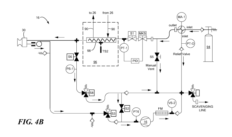
FIG. 4B shows a schematic representation of a cryotherapy system in
accordance with the present invention.
DETAILED DESCRIPTION
Referring now to FIGS. 1-3, a flow chart for a method of refrigerant delivery
from a low-pressure, native refrigerant source to a cryotherapy device is
shown in
FIG. 1 and schematic representations of a refrigerant delivery system are
shown in
FIGS. 2 and 3. In FIGS. 2 and 3, a schematic representation of a refrigerant
delivery
system is shown, the refrigerant delivery system 10 including a low-pressure
refrigerant source 12 in fluid communication with a pressurization system 14
and a
cryotherapy system 16. The low-pressure refrigerant source 12 may generally
include
a volume of refrigerant stored in a low-pressure environment within or at a
medical
facility 18, the pressurization system 14 may generally include a first
refrigerant
reservoir 20, a compressor 22, a condenser 24, and a heat exchanger 26, and
the
cryotherapy system 16 may generally include a console 28, a cryotherapy device
30.
The refrigerant delivery system 10 may also include a second refrigerant
reservoir 34,
although this reservoir 34 may be considered to be part of the pressurization
system
14 or the cryotherapy system 16, depending on the configuration of the
pressurization
system 14.
The pressurization system 14 may further include one or more processors 38
in communication with various components of the pressurization system 14 and,
optionally, with the low-pressure refrigerant source 12 and/or the cryotherapy
system
16. For example, the pressurization system 14 may include one or more
processors 38
that are capable of transmitting, receiving, and/or processing data for system
tnonitoring and control. As a non-limiting example, the pressurization system
14 may
CA 02990954 2017-12-28
WO 2017/000064
PCT/CA2016/050669
7
include one or more processors 38 for the automatic or semi-automatic control
of the
pressurization system 14, such as automatic or semi-automatic control of
system
valves. For simplicity, a processor 38 is shown in the figures as generally
being in
communication with the pressurization system 14, although it will be
understood as
noted above that the one or more processors 38 may be in communication with
one or
more specific components of the low-pressure refrigerant source 12, the
pressurization system 14, and/or the cryotherapy system 16.
The first refrigerant reservoir 20 may be in fluid communication with a
medical facility's refrigerant source. The term "medical facility" may refer
to any
facility that includes a source of refrigerant, including hospitals, walk-in
clinics, and
other facilities. Although a cryotherapy system 16 may be used in medical
facilities,
it will be understood that the method shown and described herein of
pressurizing a
refrigerant source for delivery to a given device may be adapted for use in
other
industries in addition to the medical industry.
Hospitals and other medical facilities commonly include a source of
refrigerant, such as nitrous oxide (N20), that is stored as a gas at a nornial
working
pressure of, for example, approximately 50 psig. Although different medical
facilities
may use various storage methods, a typical scheme is to store the gaseous N20
in
large tanks connected to a manifold, which regulates the pipeline pressure to
the
normal working pressure (for example, approximately 50 psig). The N20 pipeline
may be connected or connectable to any of a variety of medical systems and/or
devices. Although this low-pressure source of refrigerant (which may also be
referred
to herein as a "native source of refrigerant" or "native source of N20") may
provide
an easily accessible supply of N20 for a cryotherapy procedure, the low-
pressure N20
may have to be pressurized and liquefied before can be used in a cryotherapy
system
16, a process that is discussed in more detail below.
The method shown in FIG. 1 may generally include two phases: Phase I in
which a gaseous, low-pressure refrigerant is cooled and liquefied and stored
in a first
refrigerant reservoir 20 and Phase If in which the liquefied refrigerant is
warmed and
pressurized to facilitate movement of the refrigerant from the first
refrigerant
reservoir 20 to a second refrigerant reservoir 34.
CA 02990954 2017-12-28
WO 2017/000064
PCT/CA2016/050669
8
In the first step 110 of the method, in Phase I, a gaseous refrigerant from a
low-pressure refrigerant source 12 may pass along a first fluid flow path 44
to the first
fluid reservoir 20 of the pressurization system 14. The first fluid flow path
44 may be
a closed-loop flow path. As is discussed above, the low-pressure refrigerant
source
12 may be a native source of refrigerant, such as N20, located within a
medical
facility. The first fluid flow path 44 may include one or more valves 48 for
metering
flow of the refrigerant from the low-pressure refrigerant source 12 to the
first
refrigerant reservoir 20. Although the first refrigerant reservoir 20 may be
of any
size, shape, and configuration, it may, for example, have a cylindrical shape
with a
fluid inlet 50 at a first end and a fluid outlet 52 at a second end.
Once the refrigerant is transferred from thc low-pressure refrigerant source
12
to the first refrigerant reservoir 20, the temperature of the refrigerant may
then be
reduced in order to liquefy the gaseous refrigerant in the second step 120 of
the
method. Liquefying the gaseous refrigerant may reduce the pressure of the
refrigerant, thereby allowing a greater amount of refrigerant to be stored
within the
first refrigerant reservoir 20. Refrigerant may continue to be added to the
first
refrigerant reservoir 20 until a pressure of the liquid refrigerant within the
first
refrigerant reservoir 20 becomes equalized with a pressure of the gaseous
refrigerant
upstream of the first refrigerant reservoir 20. To monitor pressure
equalization, one
or more pressure, temperature, or other sensors 56 may be included in the low-
pressure refrigerant source 12, the first refrigerant reservoir 20, and/or
within the first
fluid flow path 44 between the low-pressure refrigerant source 12 and the
first
refrigerant reservoir 20. During Phase I, one or more valves 48A between the
first
refrigerant reservoir 20 and the second refrigerant reservoir 34 may be closed
so that
refrigerant cannot flow into the second refrigerant reservoir 34.
The first refrigerant reservoir 20 may be in a thermal exchange relationship
(that is, in thermal communication) with a first thermal exchange device 60.
As a
non-limiting example, the first thermal exchange device 60 may be an
evaporator
having have a coiled configuration and may be wrapped one or more times about
a
circumference of the first refrigerant reservoir 20. The first refrigerant
reservoir 20
and the first thermal exchange device 60 may together be located within an
insulating
container 62. The insulating container 62 may be at least partially composed
of a
CA 02990954 2017-12-28
WO 2017/000064
PCT/CA2016/050669
9
material or layers of materials that prevent or reduce the transmission of
heat.
Additionally, the insulating container 62 may be filled with, and the first
thermal
exchange device 60 and the first refrigerant reservoir 2() may be surrounded
by, a
nonfreezing liquid 64 such as methanol, propylene glycol, or other liquid
having
similar properties. The nonfreezing liquid 64 may improve heat transfer
between the
first thermal exchange device 60 and the first refrigerant reservoir 20. Thus,
the first
thermal exchange device 60 may cool the refrigerant within the first
refrigerant
reservoir 20 and the insulating container 62 may improve cooling efficiency.
The
insulting container 62 may have a shape and configuration similar to that of
the first
1() refrigerant reservoir 20, and may be sized just large enough to
accommodate the first
refrigerant reservoir 20, first thermal exchange device 60, and nonfreezing
liquid 64
therein. Further, the first refrigerant reservoir 20 optionally may be
integrated within
the insulating container 62.
In order to reduce the temperature of the refrigerant within the first
refrigerant
reservoir 20 with the first thermal exchange device 60, a secondary
refrigerant may be
circulated through the first thermal exchange device 60. This secondary
refrigerant
may flow through a second fluid flow path 70 that is different than the first
fluid flow
path 44 of the refrigerant from the low-pressure refrigerant source 12 to the
cryotherapy system 16. Put simply, the circulation of the secondary
refrigerant within
the second fluid flow path 70 may operate to selectively cool or warm
refrigerant
within the first fluid flow path 44. The secondary refrigerant may be a
refrigerant that
has an evaporation temperature of -45 "C or lower. As a non-limiting example,
the
secondary refrigerant may be R50813 or R23. From the first thermal exchange
device
60, the gaseous secondary refrigerant may flow through a second fluid flow
path 70
and through a reversing or four-way valve 74. As is described in more detail
below,
operation of the reversing valve 74 may allow for the selective cooling (when
in a
standard-flow configuration, shown in Ha 2) or warming (when in a reverse-flow
configuration, shown in FIG. 3) of the refrigerant within the first
refrigerant reservoir
20.
While still in Phase I, the gaseous secondary refrigerant may pass from the
reversing valve 74 to the compressor 22. The compressor 22 may be, for
example, a
hermetic (also referred to as a "hermetically sealed") compressor that is
configured 10
CA 02990954 2017-12-28
WO 2017/000064
PCT/CA2016/050669
compress the secondary refrigerant, thereby increasing the pressure and
temperature,
and decreasing the volume, of the secondary refrigerant. The compressed
secondary
refrigerant may then pass from the compressor 22 and back through the
reversing
valve 74 to a first three-way valve 76. When the pressurization system 14 is
in the
5 standard-flow configuration, the first three-way valve 76 may be
configured such that
the secondary refrigerant flows from the reversing valve 74, through the heat
exchanger 26, and to the condenser 24, such as a forced-air condenser. "l'he
condenser
24 may condense the secondary refrigerant, thereby reducing the temperature of
and
liquefying the high-pressure secondary refrigerant.
10 From the condenser 24, the secondary refrigerant may pass through a
second
three-way valve 78. When the pressurization system 14 is in the standard-flow
configuration, the second three-way valve 78 may be configured such that
secondary
refrigerant passes from the condenser 24 to a filter-dryer 80. The filter-
dryer 80 may
be, for example, a moisture separator, a desiccant dryer, or the like. From
the filter-
dryer 80, the secondary refrigerant may pass through a metering device, such
as an
expansion valve 84. The flow of the liquid seconday refrigerant into the first
therntal
exchange device 60 may be metered by the expansion valve 84 such that the
secondary refrigerant evaporates within the first thermal exchange device 60
and
becomes a cold gas. The gaseous secondary refrigerant then may pass from the
expansion valve 84 back to the first thermal exchange device 60. As discussed
above,
the secondary refrigerant within the first thermal exchange device 60 may
reduce the
temperature of the refrigerant within the first refrigerant reservoir 20. Once
the first
refrigerant reservoir 20 is full of refrigerant (that is, once a pressure
within the first
refrigerant reservoir 20 becomes equalized with a pressure of the refrigerant
upstream
of the first refrigerant reservoir 20), Phase II of the method may begin.
In Phase IF refrigerant from the first refrigerant reservoir 20 may be
transferred to the second refrigerant reservoir 34. The second refrigerant
reservoir 34
may be in thermal communication with a second thermal exchange device 86, and
both may be included in the pressurization system 14. Alternatively, the
second
thermal exchange device 86 may be included in the pressurization system 14,
and the
second thermal exchange device 86 may be configured such that it can be placed
in
thermal exchange with a second refrigerant reservoir 34 that is included in
the
CA 02990954 2017-12-28
WO 2017/000064
PCT/CA2016/050669
11
cryotherapy system 16. Alternatively, the second refrigerant reservoir 34 and
the
second thermal exchange device 86 may both be a part of the cryotherapy system
16.
In this case, the second fluid flow path 70 of the pressurization system 14
may be
configured to be fluidly connected to one or more components of the
cryotherapy
system 16, such as the second thermal exchange device 86 in thermal exchange
with
the second refrigerant reservoir 34. The second refrigerant reservoir 34 may
be sized
and configured to fit within the cryotherapy system console 28, although the
second
refrigerant reservoir 34 may alternatively be located outside the console 28.
Thus,
although the second refrigerant reservoir 34 is shown in FIGS. 2 and 3 as
being
located outside of the console 28 for simplicity, it will be understood that
the second
refrigerant reservoir 34 may instead be located within the console 28.
It will be understood that the pressurization system 14 may be a kit that is
adapted to be connected to both a low-pressure refrigerant source 12, such as
a native
nitrous oxide source at a hospital or other medical facility, and a
cryotherapy system
16, including the cryotherapy console 28 and device 30. For example, the
pressurization system 14 may include one or more sensors for monitoring system
parameters, such as temperature and pressure. Data collected by these one or
more
sensors 56 may be communicated to the pressurization system processor 38
and/or the
cryotherapy system console 28. Further, the pressurization system 14 processor
may
be in communication with the cryotherapy console 28 to exchange data. For
example,
the pressurization system processor 38 may send a signal to the cryotherapy
console
28 when the second refrigerant reservoir 34 is full and sufficiently cooled
for
commencement of a cryotherapy procedure. Further, the pressurization system 14
processor may enable the automatic or semi-automatic control of the
pressurization
system 14, such as automatic or semi-automatic control of the reversing valve
74,
expansion valve 84, and the first 76 and second 78 three-way valves.
In the third step 130 of the method, in Phase H. the temperature of the
refrigerant within the first refrigerant reservoir 20 may be increased or
allowed to
increase in order to facilitate transfer of the refrigerant to the second
refrigerant
reservoir 34. For example, the flow of the secondary refrigerant within the
second
fluid flow path 70 may be discontinued in order to allow the temperature, and
therefore the pressure, of the refrigerant within the first refrigerant
reservoir 2() to
CA 02990954 2017-12-28
WO 2017/000064
PCT/CA2016/050669
12
gradually increase. As a non-limiting example, the temperature of the
refrigerant may
be allowed to increase to a temperature that is slightly higher than ambient
temperature, such as approximately 30 'C ( 5 `V) and the pressure may be
allowed
to increase to approximately 900 PSI ( 50 PSI). At the same time, the
temperature of
the pressurized refrigerant may be reduced as it is transferred to the second
refrigerant
reservoir 34.
Additionally or alternatively, the pressurization system 14 may include one or
more valves that may increase the rate at with the pressure and temperature of
the
refrigerant within the first fluid is increased. For example, the reversing
valve 74 of
1() the pressurization system 14 may reverse the flow of the secondary
refrigerant
through the second fluid flow path 70. In Phase II, before the refrigerant is
transferred from the first refrigerant reservoir 20 into the second
refrigerant reservoir
34, flow of the secondary refrigerant may be reserved such that the
temperature of
refrigerant within the first refrigerant reservoir 20 is increased and the
temperature of
the refrigerant within the second refrigerant reservoir 34 as decreased.
In this reverse-flow configuration (shown in FIG. 3), secondary refrigerant
may pass through the second fluid flow path 70 through the compressor 22.
Warmed
from the compressor 22, the secondary refrigerant may then pass to the first
thermal
exchange device 60, which may function like a condenser in the reverse-flow
2() configuration because of the low-temperature condition of the
refrigerant within the
first refrigerant reservoir 20 created in Phase I. As a result, the secondary
refrigerant
may be liquefied within the first thennal exchange device 60. Due to the
thermal
exchange relationship between the first thermal exchange device 60 and the
first
refrigerant reservoir 20, the refrigerant within the first refrigerant
reservoir 20 may
increase whereas the temperature of the secondary refrigerant within the first
thermal
exchange device 60 may decrease.
The cooled secondary refrigerant may pass from the first thermal exchange
device 60 through the expansion valve 84 and the filter-dryer 80, and then
through the
second three-way valve 78. When the pressurization system 14 is in the reverse-
flow
configuration, the second three-way valve 78 may be configured such that the
secondary refrigerant bypasses the condenser 24 and instead passes front the
filter-
dryer 80 into the second thermal exchange device 86 that is in a thermal
exchange
CA 02990954 2017-12-28
WO 2017/000064
PCT/CA2016/050669
13
relationship with the second refrigerant reservoir 34. The liquid secondary
refrigerant
may evaporate within the second thermal exchange device 86 and, by virtue of
the
thermal exchange relationship, may cool the refrigerant within the second
refrigerant
reservoir 34. In some configurations, the second thermal exchange device 86
may be
included in the cryothcrapy system console 28 and may be in thermal exchange
with
the second refrigerant reservoir 34. The pressurization system 14 may be
configured
to be in fluid communication with existing cryotherapy systems, such as by
using one
or more connectors, valves, or other after-market components to connect the
two
systems.
Secondary refrigerant may then pass from the second thermal exchange device
86 to the first three-way valve 76. In the reverse-flow configuration, the
first three-
way valve 76 may be configured such that the secondary refrigerant flows from
the
second thermal exchange device 86, to the reversing valve 74, through the heat
exchanger 26, and then to the compressor 22. Secondary refrigerant may then
pass
from the compressor 22 back into the first thermal exchange device 60 within
the
insulating container 62.
The circulation of the secondary refrigerant through the second fluid flow
path
70 in the reverse-flow configuration may be discontinued once no flow is
circulating
through the valve 48 just upstream of the second refrigerant reservoir 28 or
once a
certain refrigerant level is reached inside the first refrigerant reservoir
20.
In the fourth step 140 of the method, in Phase II, the refrigerant may be
transferred from the first refrigerant reservoir 2() to the second refrigerant
reservoir
34. In the fourth step 140, one or more valves 48A between the first
refrigerant
reservoir 20 and the second refrigerant reservoir 34 may be fully or partially
open to
allow the refrigerant to flow from the first refrigerant reservoir 2() to the
second
refrigerant reservoir 34. To further facilitate the transfer, the first fluid
flow path 44
may include a vacuum source 90 that creates a pressure differential within the
first
fluid flow path 44. In this way, refrigerant may be drawn by the vacuum source
90
from the first refrigerant reservoir 20 to the second refrigerant reservoir
34. The
vacuum source 90 may also facilitate the removal of air and other impurities
form the
first 20 and second 34 refrigerant reservoirs before refrigerant is drawn from
the first
refrigerant reservoir 20. Once the refrigerant is within thc second
refrigerant reservoir
CA 02990954 2017-12-28
WO 2017/000064
PCT/CA2016/050669
14
34, the refrigerant may be circulated through a cryotherapy device 30 used to
perform
a cryotherapy procedure, such as cardiac ablation and/or mapping. Circulation
of the
secondary refrigerant within the second fluid flow path 7() may continue in
the
reverse-flow configuration during at least a part of the cryotherapy
procedure, in order
to maintain the pressurized refrigerant at a low temperature within the second
refrigerant reservoir 34.
As is discussed above, the reversing four-way valve 74 allows for fluid flow
in
a standard-flow direction and a reverse-flow direction. As is shown in FIGS. 2
and 3,
the secondary refrigerant passes through the heat exchanger 26 in both the
standard-
flow direction and the reverse-flow direction. In either flow direction,
secondary
refrigerant flowing through the portion 88 of the second fluid flow path 70
that enters
an inlet 26A of the heat exchanger 26 is always cold as it is downstream (that
is, at the
outlet side) of the thermal exchange device 60 or from the second thermal
exchange
device 86 when acting as an evaporator. Thus, the secondary refrigerant within
the
thermal exchange device 26 may cool another fluid flowing within the heat
exchange
device 26 and that is in thermal communication with the secondary fluid.
The thermal exchange device 26 may be in fluid communication with a third
fluid flow path 90 that is in fluid communication with a thennial exchange
device 92
within console 28 (shown in FIG. 4B). The thermal exchange device 92 may
include
a secondary refrigerant that is fluidly isolated from, but in thermal
communication
with, the primary refrigerant delivered to the cryotherapy device 30. This
secondary
refrigerant of the cryotherapy system 16 may flow through the third fluid flow
path 90
and be in thermal communication with (but fluidly isolated from) the secondary
refrigerant flowing within the pressurization system 14 within the thermal
exchange
device 26. Thus, the thermal exchange device 26 within the pressurization
system 14
may reduce the temperature of a secondary refrigerant of the cryotherapy
system 16.
In turn, the cooled secondary refrigerant or the cryotherapy system 16 may
subcool
the primary refrigerant within the thermal exchange device 92 of the
cryotherapy
system 16. As is shown in FIG. 4B, the first secondary refrigerant may enter a
first
inlet 26A the thermal exchange device 26, exit a first outlet 26B of the
thermal
exchange device 26, enter an inlet 22A of the compressor 22, and exit an
outlet 22B
of the compressor 22. The secondary refrigerant of the cryotherapy system 16
may
CA 02990954 2017-12-28
WO 2017/000064
PCT/CA2016/050669
enter a second inlet 26C of the thennal exchange device 26 and exit a second
outlet
26D of the thermal exchange device 26. Within the cryotherapy system 16, the
primary refrigerant may pass from a fluid reservoir 94 into a first inlet 92A
of the
thermal exchange device 92, within which the primary refrigerant is subcooled
by the
5 secondary refrigerant within the third fluid flow path 90, out a first
outlet 92B of the
thennal exchange device 92, and into the cryotherapy device 30. Likewise, the
secondary refrigerant within the third fluid flow path may enter a second
inlet 92C of
the thermal exchange device 92, and may exit from a second outlet 92D of the
thermal
exchange device. Although not shown in FIGS. 2 and 3, it will be understood
that
10 the primary refrigerant of the cryotherapy system 16 may pass through
various other
system components, such as those shown in FIG. 4B.
As is shown in FIG. 4A, currently known cryotherapy systems may include
consoles having an independent refrigeration circuit 96, which may include a
thermal
exchange device 98, a condenser 100, and a compressor 102. By including the
15 thermal exchange device 26 within the pressurization system 14, the
condenser 100,
compressor 102, and other components (for example, valves, tubing, and a
compressor fan) can be removed from the console (as shown in FIG. 4B). It will
be
understood that the cryotherapy system 16 in use with the pressurization
system 14
may not be exactly as shown in FIGS. 4A and 4B.
It will be understood that the medical facility, pressurization system 14,
and/or
the cryotherapy system 16 may include system components in addition to those
shown
in the figures, such as one or more valves, computers, processors, fluid
reservoirs,
user input devices, sensors, vacuum sources, power generators, or the like.
Although
not shown, the pressurization system 14 may include one or more temperature
sensors
and/or pressure sensors located throughout the system for monitoring fluid
temperature within the first and/or second fluid flow path 70. Additionally,
the
pressurization system 14 and/or the cryotherapy system 16 may include one or
more
displays, audio alerts, visual alerts, or the like for communicating system
conditions
to a user. Further, it will be understood that although each of the second
fluid flow
path 70 components of the pressurization system 14 may include an inlet port
and an
outlet port, whether each port functions as an inlet or an outlet may be
determined by
CA 02990954 2017-12-28
WO 2017/000064
PCT/CA2016/050669
16
whether the second fluid flow path 70 is operating in the standard-flow
configuration
or the reverse-flow configuration.
It will be appreciated by persons skilled in the art that the present
invention is
not limited to what has been particularly shown and described herein above. In
addition, unless mention was madc above to the contrary, it should be noted
that all of
the accompanying drawings are not to scale. A variety of modifications and
variations are possible in light of the above teachings without departing from
the
scope and spirit of the invention, which is limited only by the following
claims.