Note: Descriptions are shown in the official language in which they were submitted.
CA 02990958 2017-12-28
Method and Plant for Processing and Drying of Wood Shavings,
Woodchips or Other Solid Materials in Small Pieces that are of Organic and/or
Mineral
Origin
The invention relates to a method and a plant for the drying of wood shavings,
woodchips
or other solid materials in small pieces that are of organic and/or mineral
origin. The
materials consist of a plurality of solid particles and are pourable. They are
also called bulk
material or piles. The method according to the invention and the plant
according to the
invention are suitable in particular for use in a method and a plant for
producing wood pellets
or other solid granules from material in small pieces that are of organic
and/or mineral
origin.
Wood pellets are rod-shaped granules that consist of sawing or planing
shavings, wood
chips, wood shredder material or other byproducts, or waste from the timber
and forest
industry. Other solid granules made of material in small pieces that are of
organic and/or
mineral origin can be made for example of straw, sunflower seed shells, olive
pits, olive
press pomace, rice husks, meat or fish waste and other biogenic remnants from
the
agriculture industry, meat, fish or food industry among other things with the
addition of
mineral components in different combinations and proportions. In the
production of wood
pellets, the supplied material is prepared to be pelletized, in particular by
drying, if
applicable also by maceration and conditioning. The pellets are pressed from
the prepared
material. For this, an edge runner press for example is used in which the
material is pressed
through a die with holes according to the desired pellet diameter. The lignin
contained in
the material is released by the heating during conditioning, or respectively
during the
pressing, and bonds the individual wood particles to each other. Furthermore,
it is known to
add bonding agent to the granulated material in order to bond the particles
together. After
exiting the die, a knife cuts the pellet strands to the desired length. Then
the pellets are
cooled and thereby solidified.
DE 10 2013 224 204 A1 describes a plant for producing wood pellets or other
solid granules
that can be transported, set up and moved to a different location with less
effort, and that
enables energy-optimized operation. The plant is arranged at least partially
in individual
1
CA 02990958 2017-12-28
transportable containers that can be assembled in a modular manner for at
least a substantial
part of the plant, wherein at least the apparatus for cooling designed as a
duct cooler is
completely arranged in a container. At least one of the apparatuses for
adding, preparing,
drying, pressing, cooling and discharging is arranged in a container with a
vertical
longitudinal axis. In the exemplary embodiment, the dryer is a belt dryer, and
a storage silo
for intermediate storage is arranged downstream of the dryer. From the storage
silo, the
material is conveyed to the dry mill, where it is crushed to the optimal
particle size.
During the drying in the belt dryer, heat loss occurs due to the fact that the
heated air is
released into the atmosphere after crossing over the belt and the drying
material lying on it.
Since a heterogeneous drying takes place, in practice only the uppermost layer
is often
scratched off and the layer lying underneath it is fed back to the drying.
Energy loss for the
operation of the powerful ventilators is added to the high heat loss.
Drying in drum dryers is also known. These work with a burner, which heats the
heating
gas to a very high temperature e.g. of 400 C. The waste heat still has a high
temperature of
e.g. 90 C and is not used. It is also disadvantageous that volatile organic
compounds (VOCs)
and lignins are leached from wood particles. The quality of the material is
hereby reduced.
The lignin is missing as the bonding agent during the pelletization.
DE 10 2006 061 340 B3 describes an apparatus for producing wood pellets with
at least one
assembly module for adding, drying, pressing and discharging. The assembly
modules are
introduced in a vertical arrangement of the respective functional assemblies
in
internationally standard containers (12 to 20 foot containers). A plurality of
containers
forming a horizontal and/or vertical row are connected to each other by
electrical and/or
pneumatic media lines, and one of the containers is connectable to a locally
available media
source. The easy and quick assembly of the plant is advantageous which
consists of prepared
assembly modules.
The plant comprises a dryer, which comprises vertical drying ducts for wood
shavings,
which extend over two containers set horizontally to each other. On the top,
wood shavings
enter the drying duct and exit again on the bottom end. Ventilators and heat
exchangers,
2
CA 02990958 2017-12-28
which are arranged on different sides of the drying duct, ensure
dehumidification of the
wood shavings. The upper ventilator suctions air heated by the upper heat
exchanger through
the drying duct and the lower ventilator suctions air heated by the lower heat
exchanger in
the opposite direction through the drying duct. A high throughput should
hereby be
achieved. The drying air suctioned through the drying duct is released to the
surroundings.
The flexibility with respect to an adjustment of the dryer to different
throughputs is low.
Based on this, the object of the invention is to create a method and a plant
for the drying of
wood shavings, woodchips or other solid materials in small pieces that are of
organic and/or
mineral origin with improved energy efficiency and increased flexibility.
The object is solved by a method with the characteristics of claim 1.
Advantageous
embodiments of the method are cited in the dependent claims.
The method according to the invention for the drying of wood shavings,
woodchips or other
solid materials in small pieces that are of organic and/or mineral origin
includes the
following steps:
- in a first drying step, the material is pre-dried by means of a first
preheated drying gas,
- in a second drying step, the dried material from the first drying step is
dried by means of
a second preheated drying gas,
- ambient air is heated and supplied to the second drying step as a second
preheated drying
gas,
- the dried material from the second drying step is cooled by means of a
cooling gas and
- the cooling gas heated by the cooling of the material and/or the second
drying gas cooled
in the second drying step is supplied to the first drying step as the first
drying gas.
3
CA 02990958 2017-12-28
In the case of the method according to the invention, energy is saved through
the repeated
use of the energy for the heating of the ambient air. For this, the second
drying gas is also
used in the first drying step after cooling down in the second drying step
and/or the thermal
energy bound in the material is used for drying in the first drying step. The
drying gas is
preferably air or a mixture of combustion gas and air.
According to a preferred embodiment of the invention, in a third drying step,
the dried
material from the second drying step is dried by means of the second preheated
drying gas
and the second preheated drying gas cooled in the third drying step to a
temperature above
the temperature of the ambient air is supplied to the second drying step. In
this embodiment,
the energy of the second preheated drying gas is used for the third drying
step and the second
drying step and the energy efficiency is further improved. The dried material
from the
second drying step is cooled by means of the cooling gas only after passing
through the third
drying step.
Furthermore, the invention includes embodiments, in which the material passes
through
more than three drying steps. The second preheated drying gas is preferably
first used for
the respective last drying step and after a cooling down to a temperature
above the ambient
temperature for at least one upstream drying step.
According to a further embodiment, the dried material from the first or the
second drying
step undergoes a rest period, in which the water content within the particles
of the material
are more or less equalized and the material is dried in the second or third
drying step after
the rest period is complete. During the rest period, which is preferably one
half to two hours,
further preferably one to one and a half hours, an equalization of the water
content of the
cross-section of the particles more or less results so that water moves from
the core to the
surface of the particles. The efficiency of the subsequent drying step is
hereby improved.
According to a further embodiment, the dried material from the first drying
step or from the
second drying step is macerated and then supplied to the second drying step or
the third
drying step. Through the maceration of the material, the humidity inside the
particles on the
surface is freed so that the subsequent drying can be performed more
efficiently.
4
CA 02990958 2017-12-28
According to a further embodiment, the dried material is macerated between two
drying
steps and undergoes a rest period. The maceration and rest period can take
place in any
order. The particles are preferably first macerated and then undergo a rest
period. The dried
material is preferably macerated between the same drying steps and undergoes a
rest period.
The invention further comprises designs in which the maceration takes place
between two
different drying steps than the rest period.
According to a further embodiment, the cooled and humidified drying gas from
the first
drying step and/or from the second drying step is released into the
surroundings. In this
embodiment, largely cooled drying gas is released into the surroundings.
According to a further embodiment, the cooled and humidified drying gas from
the second
drying step is dried and the dried drying gas is mixed with the ambient air
and is supplied
to the second or third drying step as a second drying gas. In this embodiment,
the remaining
thermal energy of the drying gas from the second drying step is used for the
heating of the
ambient air.
According to a further embodiment, the condensed water coming from the drying
of the
drying gas from the second drying step is supplied to a heat pump and the heat
brought to
an increased temperature level by the heat pump is used to heat the ambient
air. The energy
bound in the water in the drying air is hereby also reclaimed for the process
and the energy
efficiency is further improved.
According to a further embodiment, a portion of the cooled, second drying gas
from the
third drying step is mixed with the heated cooling gas and is supplied to the
first drying step
as the first drying gas. The usage of the thermal energy of the second drying
gas is hereby
further improved.
According to a further embodiment, the ambient air and/or the dried drying gas
is heated by
means of a heat exchanger and/or by means of a heat burner. According to one
embodiment,
the heat exchanger is operated by means of the energy supplied by the heat
pump and/or
with the waste heat from a production process and/or with the heat from a
block heat and
5
CA 02990958 2017-12-28
power plant. When using a heat burner, wood dust or wood pellets from the
method or
another fossil fuel can be used. The use of a heat burner has the advantage
that the drying
gas has a high percentage of heating gases, which reduces the risk of
combustion of
combustible or respectively easily combustible material as a result of the
greatly reduced
oxygen content of the heating gases.
According to a further embodiment, the first and/or the second and/or the
third drying step
takes place in a manner such that the material passes through a vertical
drying path from top
to bottom and the drying gas is guided though the drying path in the cross-
current flow,
wherein the drying path is subdivided into individual sections, in which the
mass flow of
the drying gas, which is guided transversely through it in a section of the
drying path, is
adjustable. Larger or smaller volumetric flows of the drying gas can hereby be
directed
through the drying path in different sections of the drying path. This enables
an adjustment
for the respectively used material. In the case of a coarser material (e.g.
wood chips),
repeated deflection of the drying gas at relatively high speeds of the drying
gas while passing
through the drying path is advantageous because a drying hereby takes place
and courser
material is less easy to discharge laterally from the drying path. In
contrast, in the case of
finer material (e.g. shavings), a less frequent deflection and thus a lower
flow speed of the
drying gas can be advantageous when passing through the drying duct.
According to a further embodiment, the ambient air is heated in that it is
suctioned by a fan
in a mainly horizontal direction by a box-shaped, vertical arrangement of four
heat
exchangers and is heated while passing through the heat exchangers and is then
suctioned
up in the vertical direction by the fan arranged below the heat exchangers and
is supplied
by it to the second or third drying step. A high heat transfer capacity is
hereby reached,
whereby the amount of space needed for a device for performing the method is
low.
Furthermore, the object is solved by a plant with means for performing the
steps of the
method according to one of claims 1 to 11.
Furthermore, the object is solved by a plant having the features of claim 12.
Advantageous
embodiments of the plant are specified in the dependent claims.
6
CA 02990958 2017-12-28
The plant according to the invention for the drying of wood shavings,
woodchips or other
solid materials in small pieces that are of organic or mineral origin suitable
for performing
the method according to one of claims 1 to 11 includes:
- a first drying unit, which is designed to pre-dry the material in a first
drying step by
means of a first preheated drying gas,
- a second drying unit, which is designed to dry the dried material from the
first drying
unit by means of a second preheated drying gas,
- a gas preparation unit (gas heating unit), which is designed to heat
ambient air and
provide it as a second preheated drying gas for the second drying unit,
- a cooling unit, which is designed to cool the dried material from the
second drying stage
by means of a cooling gas and
- lines, which supply the cooling gas heated in the cooling unit and/or the
second drying
gas cooled in the second drying unit to a temperature above the ambient
temperature as
the first drying gas of the first drying unit.
The plant is a preferred form of the implementation of the initially mentioned
method and
has its energetic advantages.
According to a preferred embodiment, a third drying unit is present, which is
designed to
dry the material from the second drying unit by means of the second preheated
drying gas
in a third drying step, and to supply the second drying gas cooled to a
temperature above
the ambient temperature to the second drying stage. This further improves the
energy
efficiency of the plant.
According to a further embodiment, the plant comprises a resting container,
which is
designed so that the dried material from the first drying step or from the
second drying step
undergoes a rest period in the resting container, in which the water content
within the
7
CA 02990958 2017-12-28
particles of the material is more or less equalized, wherein the material is
provided for
further drying in the second drying step or in the third drying step after
undergoing the rest
period. The efficiency of the drying is hereby further improved.
According to a further embodiment, the plant comprises a maceration apparatus,
which is
designed to macerate the dried material from the first drying unit or from the
second drying
unit and to provide it for drying in the second drying unit or in the third
drying unit. The
efficiency of the drying is hereby further improved.
According to a preferred embodiment, the drying plant includes both a resting
container as
well as a maceration apparatus, generally in any order; however, the material
preferably
passes through the maceration apparatus before the resting container.
Furthermore, the
maceration apparatus can be arranged between two different drying units than
the resting
container.
According to a further embodiment, the first drying unit and/or the second
drying unit
comprises an outlet to the surroundings for releasing cooled and humidified
drying gas. Due
to the low temperature of the drying gas in the first drying unit and/or the
second drying
unit, it only still has a low energy and can be released to the surroundings.
According to a further embodiment, the plant comprises a gas drying unit,
which is designed
to dry the cooled and humidified drying gas from the second drying unit and
provide it for
the gas preparation unit for mixing with the ambient air. Thermal energy from
the cooled
drying gas from the second drying unit can hereby be used to heat the ambient
air.
According to a further embodiment, the plant comprises a heat pump, which is
designed to
raise the heat of the water condensed out in the gas drying unit to an
increased temperature
level and to provide it to the gas preparation unit in order to heat the
ambient air. This further
increases the energy efficiency of the plant.
8
CA 02990958 2017-12-28
According to a further embodiment, the third drying unit is connected with the
line between
the cooling unit and the first drying unit via a line, in order to mix cooled,
second drying air
from the third drying unit with the heated air from the cooling unit and to
supply it to the
first drying unit as first drying air.
Furthermore, the object is solved by a plant for the drying of wood shavings,
woodchips or
other solid materials in small pieces that are of organic and/or mineral
origin, in particular
according to one of claims 12 to 19, which has a gas preparation unit (gas
heating unit) for
generating a heated drying gas, which has a rectangular housing with heat
exchangers
arranged at a distance from the bottom end in four vertical side walls and
respectively gas-
permeable in the horizontal direction, a fan arranged in the housing below the
heat
exchangers with an air inlet on the top side and an air outlet, which is
connected with a
drying unit via a line. The gas preparation unit enables the transfer of high
heating capacity
with minimal space requirements.
According to a preferred embodiment, each heat exchanger of the gas
preparation unit
comprises a register and a tube bundle on the inside of the register. This is
advantageous for
an energetically beneficial pre- and post-heating of the suctioned in drying
gas. The tube
bundle is also preferably a component of all heat exchangers.
Furthermore, the object is solved by a plant for the drying of wood shavings,
woodchips or
other solid materials in small pieces that are of organic and/or mineral
origin with the
features of claim 22. Advantageous embodiments of the plant are specified in
the dependent
The plant according to the invention for the drying of wood shavings and other
solid
materials in small pieces that are of organic and/or mineral origin, in
particular according to
one of claims 12 to 21, comprises a drying unit with at least one vertical
drying duct and
vertical gas ducts on both sides of the drying duct, wherein the duct walls
between the drying
duct and the gas ducts are perforated, the drying duct has an inlet on top for
the material to
be dried and an outlet on the bottom for dried material, at least one of the
gas ducts on the
bottom end has a gas inlet and at least one of the gas ducts on the top end
has a gas outlet
9
CA 02990958 2017-12-28
and horizontal shut-off apparatuses with an adjustable passage cross-section
are arranged
within the gas ducts.
In the case of the drying unit, the passage cross-section can be changed from
a maximally
opened setting to a maximally closed setting. The passage cross-section is
preferably
infinitely adjustable between the maximally closed and the maximally opened
position. In
the maximally closed position, the passage cross-section is preferably
completely shut,
except for inevitable leaks, which the shut-off apparatus can have. By means
of shut-off
apparatuses, it is possible to adjust the volumetric flow of the drying gas,
which is deflected
below a shut-off apparatus transversely through the drying duct. By means of
the shut-off
apparatuses, the flow direction of the drying gas through the drying duct can
be changed
repeatedly in the one direction and the other. It is also possible to adjust
the flow speed of
the drying gas in high sections of the drying duct by adjusting the shut-off
apparatuses. The
drying in the drying unit can hereby be adjusted flexibly for the respective
material to be
dried.
According to a further embodiment, the duct walls between the drying duct and
the gas ducts
are perforated sheets. According to a preferred embodiment, the holes in the
sheets are
covered on the top so that material passing through the drying duct from above
is prevented
from escaping into a gas duct through the holes in the walls.
According to a preferred embodiment, at least one of the duct walls between
the drying duct
and gas ducts is guided laterally on the vertical guide apparatuses and is
connected with a
displacement apparatus on the upper end, which is designed to displace the
duct wall within
the guide apparatuses upwards and downwards vertically in order to break down
material
bridges between the duct walls of the drying duct. A blocking of the drying
duct by the
material to be dried can hereby be prevented.
According to a further embodiment, both duct walls on the upper end are
connected with a
displacement apparatus, wherein the displacement apparatuses are synchronized
so that they
displace the two duct walls in the opposite direction. Material bridges
between the duct
walls of the drying duct are hereby broken down particularly effectively.
CA 02990958 2017-12-28
According to a further embodiment, the shut-off apparatuses are lamella
apparatuses each
with at least one lamella pivotable about a horizontal axis. Different passage
cross-sections
can be released by pivoting the lamella. Each shut-off apparatus preferably
comprises
several parallel lamellas pivotable about a horizontal axis.
According to a further embodiment, drying ducts are arranged on both sides of
a gas duct
supplying a drying gas, and an exterior gas duct is arranged on the outsides
of each drying
duct. A particularly compact construction of a drying unit with a high
efficiency is hereby
achieved.
According to a further embodiment, which concerns all plants according to the
invention, at
least one component is arranged in at least one container, wherein a container
accommodates
entirely or partially one or more components of the plant. This embodiment is
particularly
easy to install and suitable for mobile use at different locations. The plant
is preferably
designed so that the components are arranged entirely or partially in several
containers,
which can be combined to form at least one main part of the plant.
Containers in terms of the present application are preferably frame
constructions with open
walls or with one or more closed walls. The frame construction preferably has
packing and
connecting dimensions and properties like stackability, transportability,
fastening amongst
each other etc., according to the ISO standard ISO 668:2013. The containers
preferably have
self-supporting frame constructions. The frame constructions are preferably
simultaneously
an integral structural part of one or more components of the plant. The
components or
respectively the machines contained therein are permanently integrated into
the frame
construction. The embodiment of the containers preferably differs from the
embodiment of
conventional standard containers, e.g. with respect to load-bearing capacity,
frame strength,
number and type of struts, etc. However, within the framework of the
invention,
conventional standard containers can generally also be used for accommodating
components or parts thereof.
According to a further embodiment, the gas preparation unit and/or the drying
unit is/are
arranged entirely or partially in a vertical container. With respect to the
structural design of
11
CA 02990958 2017-12-28
the cooling unit and the gas preparation unit, this embodiment is particularly
effective and
space-saving.
According to a preferred embodiment, at least one structural element of one
component of
the plant is at least one structural element of the container. According to a
preferred
embodiment, at least one structural element of the gas preparation unit and/or
the drying
unit is a component of the frame construction and/or the container shell. At
least one frame
part and/or one outer wall of the gas preparation unit and/or the drying unit
is preferably a
structural element, which is simultaneously at least partially a component of
the container
shell. As a component of the container shell, the structural element
simultaneously forms at
least partially the outer shell of the container.
The invention will be further explained below with reference to the
accompanying drawings
of exemplary embodiments. The drawings show in:
Fig. 1 a plant for producing wood pellets in a roughly schematic
representation;
Fig. 2A a first version of a plant for drying for the plant for
producing wood pellets
in a schematic representation;
Fig. 2B a second version of a plant for drying for the plant for
producing wood pellets
in a schematic representation;
Fig. 3A setup of the components of the plant in Fig. 2A in a plan view;
Fig. 3B setup of the components of the plant in Fig. 2B in a plan view;
Fig. 4 a gas preparation unit of the same plant in a perspective view
transversely
from the side;
Fig. 5A+B the same gas preparation unit in a vertical section (Fig. 5A) and
in a
horizontal section (Fig, 5B);
Fig. 6 a drying unit of the same plant in a perspective X-Ray image;
Fig. 7 the same drying unit in a vertical section;
Fig. 8A-B the same drying unit with different settings of the shut-off
apparatuses,
respectively in a roughly schematic vertical section.
12
CA 02990958 2017-12-28
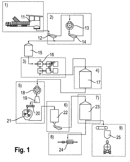
In Fig. 1, different modules of a plant for producing wood pellets are framed
by dashed
lines. Preferably, the modules each consist of one or more containers
containing the
components of the plant. This is the case in the example in modules 1, 2, 5,
6, 8 and 9. The
module 3 comprises a plant for drying according to the invention and the
modules 4 and 7
are silos in the example.
Raw materials such as sawdust or wood chips are delivered in a truck and
unloaded in the
raw material receiving unit 11. If applicable, the raw material may be stored
sorted
according to quality, or respectively properties, on a site and supplied to
the plant in
appropriate mixtures, for example using a wheel bearing. The raw material is
fractionated
in the plant by means of the sieve 12. Coarse fraction is macerated in the wet
macerator 13.
After being macerated in the wet macerator 13 and passing through a sieve 14,
the fine
fraction together with the fine fraction from the sieve 12 is also added to
the buffer and
metering tank 15.
This is followed by the drying in the plant for drying 16 and subsequent
interim storage in
the storage silo 17. Next comes the metered conveyance to a dry mill 18 where
the material
is macerated to the optimum grain size. Then the material is prepared to be
pressed in a
conditioner 19. After passing through a mixing worm gear 20 into which binding
agent may
be supplied, the prepared raw material enters a press 21.
Following the pressing process in the press 21, hot pellets are cooled in a
cooler 22 and
introduced into the storage silo 23 to be stored. After being stored in the
storage silo 23, the
pellets are packaged into small packages in a packaging plant 24 or are loaded
directly as
bulk material in a loading plant 25.
The explanation of two alternative plants for drying 16 takes place based on
Fig. 2a, b and
3a, b. In Fig. 2a and b, the temperatures of the drying gas are noted in
degrees Celsius and
the humidities of the material in weight percent at different positions in the
plant. In both
alternatives, ambient air with a temperature of 10 C and 70% relative humidity
is supplied
to the plant. The supplied material consists of wood chips with a water
content of 45 wt.-
percent and an average particle size ranging from 30 to 50 mm.
13
CA 02990958 2017-12-28
In both alternatives, the material to be dried passes through in succession a
first drying unit
101, a second drying unit 102, an intermediate macerator 103, a resting
container 104, a
third drying unit 105 and a cooling unit 106.
In both alternatives, ambient air is heated in a gas preparation unit 107 and
supplied to the
third drying unit 105 as a second preheated drying gas. The second drying gas
cooled to a
temperature above the ambient temperature by the heating of the material in
the third drying
unit 105 is supplied to the second drying unit 102 in order to dry the
material supplied to
this drying unit from the first drying unit 101.
The cooling unit 106 is supplied with ambient air for the cooling of the
material heated
during the drying in the third drying unit 105.
The ambient air heated in the cooling unit 106 is supplied to the first drying
unit 101 as the
first drying gas in order to pre-dry the material supplied to it.
The material pre-dried in the first drying unit 101 is dried further in the
second drying unit
102.
After the second drying unit 102, the material is macerated in the maceration
unit 103, in
order to release the moisture on the surface of the material. It is then
stored for a certain rest
period of e.g. one to one and a half hours in the resting container 103 so
that the liquid is
equalized over the cross-section of the particles.
After the rest period, the material is completely dried in the third drying
unit 105. Finally, it
is cooled in the cooling unit 106.
The dried material then enters the storage silo 17.
The first drying gas cooled in the first drying unit 101 is released into the
surroundings. In
the alternatives in Fig. 2A, the second drying gas cooled in the second drying
unit 102 is
released into the surroundings. In the alternatives in Fig. 2B, the second
drying gas cooled
14
CA 02990958 2017-12-28
and humidified in the second drying unit 102 is supplied to a gas drying unit
108. In the gas
drying unit 108, the gas temperature is lowered for example by spraying with
water and a
steam condensation is performed. The condensed water from the sump of the gas
drying
unit 108 can be supplied to a heat pump, which brings the thermal energy to a
suitable
temperature level for the drying gas preparation. The drying gas dried in the
gas drying unit
108 is mixed with the ambient air in the gas preparation unit 107.
The gas preparation unit 107 in the alternatives in Fig. 2A works with a heat
exchanger,
which is supplied with heating medium at a temperature of e.g. 100 C, which
leaves the
heat exchanger at e.g. 60 C. The second drying gas is heated to a temperature
of approx.
80 C. The alternative in Fig. 2B has a burner. The fuel is for example dried
and finely
macerated biomass (e.g. wood dust). This design is particularly suited and
preferred for
setup and locations without or with insufficient external heat sources (CHP ¨
combined heat
and power) plants, process waste heat, etc.).
A further advantage of the gas preparation unit 107 with burner is the
improvement of
operational safety, since the use of the low-oxygen exhaust gas from the gas
preparation
unit 107 virtually effectuates fire protection in closed-circuit mode. Only
the amount of air
necessary for the complete combustion of the fuel is supplied so that the hot
combustion gas
(e.g. approx. 600 C to 800 C) with the dried drying gas from the gas drying
unit 108 is
mixed to form a second drying gas with the desired drying gas temperature
(approx. 100 C)
and is supplied to the third drying stage 105. The heating of the drying gas
to a temperature
of max. 120 C, preferably max. 100 C, reduces at least the volatilization of
high-energy
components of the material that are important for the production of wood
pellets, e.g. lignin.
The low drying temperature also reduces the fire risk.
The structure and functionality of an exemplary embodiment of the gas
preparation unit 107
is explained based on Fig. 4 and 5.
The gas preparation unit 107 has a rectangular housing 201 with heat
exchangers 203
arranged at a distance from the bottom end in four vertical side walls 202 and
respectively
gas-permeable in the horizontal direction. Each heat exchanger 203 comprises a
plate-like
CA 02990958 2017-12-28
register 204, which is arranged in the opening 205 of a side wall 202.
Furthermore, the heat
exchangers 203 comprise a tube bundle 206, which is designed as a spiral,
spirally wound
tube coil with vertical winding axis.
Below the heat exchangers 203, a fan 207 with vertical air inlet 208 and
radial air outlet 209
through a side wall of the housing is arranged in the housing 201.
The gas preparation unit 107 is designed as a container 210, i.e. it has the
dimensions of a
standard container. The side walls 202 are an integral component of the
container shell.
Revision flaps 211 are present in one of the side walls on the bottom.
The container 210 can be transported in horizontal alignment. During
operation, it has the
vertical alignment shown in Fig. 4.
The fan 207 suctions the ambient air to be heated through the register 204 and
through the
tube bundle 206. When passing through the register 204, the ambient air is
preheated and is
post-heated when passing through the tube bundle 206. The preheated drying gas
enters e.g.
the third drying unit from the gas preparation unit 107.
The tube bundle 206 is preferably designed as a fin tube bundle and serves as
a second
heating stage. Hot water or another suitable liquid/mixture first passes
through the tube
bundle 206 and then through the register 204. After passing through the
registers 204, the
cooled medium is lead back to the external heat source as return flow.
The registers 204 are preferably lamella heat registers. The fan 207 is e.g. a
radial ventilator
or a side-channel compressor.
The gas preparation unit 107 has a particularly good surface area utilization
and an improved
utilization of the supplied heat. Moreover, through the arrangement of the
heat exchangers
203 in the upper area, the contamination of the gas preparation unit 107 with
swirling dust
on the floor is reduced. This increases the efficiency of the heat exchangers
203 and extends
the cleaning intervals.
16
CA 02990958 2017-12-28
Based on Fig. 6 to 8, the structure and function of one of the drying units
101, 102, 105
designed as a duct dryer is explained.
The duct dryer 101, 102, 105 has a central vertical gas duct 301 and drying
ducts 302, 303
on both sides of the gas duct. The duct dryer has outer gas ducts 304, 305 on
both outsides
of the drying ducts 302, 303.
The gas ducts 301, 304, 305 and drying ducts 301, 303 are separated from each
other by
perforated duct walls 306, 307, 308, 309, which are preferably designed as
perforated sheets.
The drying ducts 302, 303 and gas ducts 301, 304, 305 have respectively a
mainly
rectangular cross-section.
Shut-off apparatuses 310 with an adjustable passage cross-section, which are
designed as
lamella apparatuses each with at least one lamella 311 infinitely pivotable
about a horizontal
axis, are arranged within the gas ducts 301, 304, 305. In the example, there
are three lamellas
311 per shut-off apparatus 310.
In the example, the shut-off apparatuses 310 are arranged in the vertical
direction at three
positions distributed almost evenly across the height of the duct dryer.
Drying gas is supplied to the central gas duct on the bottom via an inlet line
312 and a
distributing funnel 313. Collector lines 314, 315 are present on the upper end
of the outer
gas ducts 304, 305, through which the humidified and cooled drying gas enters
a discharge
line 316.
The material to be dried is supplied via a filling apparatus, which is
designed for example
as a vertical worm gear 317. In the vicinity of the bottom end, the worm gear
317 catches
supplied material and transports it up to near the upper end of the duct dryer
101, 102, 105.
There, the material is supplied to distribution apparatuses 318, which supply
it to the upper
ends of both drying ducts 302, 303.
17
CA 02990958 2017-12-28
The duct walls 306, 307, 308, 309 of the drying ducts 302, 303 are guided on
vertical guide
apparatuses on their perpendicular edges. On top, each duct wall 306, 307,
308, 309 is
connected with a displacement apparatus 319, which is designed to raise and
lower the duct
wall vertically, for example over a distance of a few centimeters (e.g. 5 to
10 cm). The
displacement apparatuses are synchronized such that they displace the walls,
which delimit
the same drying duct 302, 303, in the opposite direction. Each displacement
apparatus 319
is e.g. a hydraulic displacement apparatus, in particular a hydraulic
cylinder. Each
displacement apparatus 319 is preferably arranged in a gas duct 301, 304, 305.
A grooved floor 320 is present on the bottom end of each drying duct 302, 303,
through
which the dried material can be released in a controlled manner. By means of a
spiral floor
321, 322, the released material is guided into a collection and discharge
spiral 323.
The refilling of the drying ducts 302, 303 is controlled so that the drying
ducts are
completely filled with the material to be dried and no false air is created.
The duct walls 306, 307, 308, 309 are perforated so that material cannot pass
through
laterally and fall into a gas duct 301, 304, 305.
The drying gas passes through the inlet line 312 and the distribution funnel
313 into the
central gas duct 301 and flows transversely through the perforated duct walls
306, 307, 308,
309 through the drying ducts 302, 303. The drying gas enters the collection
lines 314, 315
through the outer gas ducts 304, 305 and is then removed by the discharge line
316.
The guiding and quantity distribution of the drying gas in the drying ducts
302, 303 takes
place by means of shut-off apparatuses 310. These can be more or less open. It
is hereby
possible, depending on the material properties (particle size, bulk density,
etc.) and the flow
rate (kg per hour) of the material to be dried, to set the guiding of the
drying gas via the
different height sections of the drying ducts 302, 303.
In the case of fine-grain raw materials with a large surface area and large
air resistance, a
simple crossing of the drying duct 302, 303 can be advantageous, as shown in
Fig. 8A. In
18
CA 02990958 2017-12-28
the case of course-grain raw materials with correspondingly lower air
resistance, single or
multiple crossings can be advantageous, as shown in Fig. 8B and C. Fine
particles, which
unintentionally enter the gas ducts 304, 305, can be distributed by means of
spirals 324, 325,
which are located on the bottom end of the outer drying ducts 304, 305.
Furthermore, the guiding of the drying gas according to Fig. 8B and C is
advantageous
during partial load mode or when the plant is setup for low hourly output. It
is thereby
possible to design the plant with two instead of three drying stages.
In another design, it is possible to dry material to considerably lower water
contents of e.g.
4 wt.-% or 2 wt.-% by designing the duct dryer 101, 102, 105 with additional
drying ducts
and gas ducts.
The duct dryer 101, 102, 105 is preferably designed in a single container 326.
The outer
walls of the ducts 301 to 305 thereby simultaneously form parts of the shell
of the container
326. The container 326 is horizontally transportable and is set up vertically
during operation,
as shown in Figures 6 to 8.
19