Note: Descriptions are shown in the official language in which they were submitted.
84119189
- 1 -
Description
Vortex pump
The invention relates to a non-chokable pump comprising
an impeller which has blades for delivering solids-
containing media.
Such non-chokable pumps are also referred to as vortex
pumps, the delivery power of which is transferred from
a rotating plate provided with blades, the so-called
non-chokable impeller, to the flow medium. Non-chokable
impellers are particularly suitable for delivering
media mixed with solid additions, such as for example
dirty water. The non-chokable impeller is a radial
impeller which has a large passage for the solids
contained in the delivery medium and has a low
susceptibility to faults.
A non-chokable pump for delivering liquids mixed with
solid additions is described in WO 2004/065796 Al.
There is a spacing between the impeller and the
suction-side casing wall r in order that solid bodies
can pass through the non-chokable pump without
blockages. The transition from the suction-side casing
wall to the wall of the casing space, which space is.
situated radially with respect to the impeller, is
realized smoothly. The casing space is of asymmetric
design.
A non-chokable pump whose impeller consists of a
support plate equipped with open blades is described in
EP 1 616 100 Bl. The blades have different heights. A
suction-side casing wall runs conically. The spacing of
the casing wall to the front edges of the relatively
high blades of the impeller decreases with diameter. A
passage with a minimum extent follows a front edge of a
Date Recue/Date Received 2022-11-02
84119189
- 2 -
blade of relatively low height, which blade is inclined toward the
impeller outlet, in a constant manner.
Referred to as a ball passage is a free, non-constricted impeller
passage. It describes the largest permissible diameter of the solids
for ensuring a blockage-free passage. It is specified as a ball diameter
in millimeters. The ball passage corresponds, at most, to the nominal
width of the suction or discharge connector. In order that this maximum
possible ball passage is achieved in conventional non-chokable pumps,
it is also necessary that, inside the casing, the spacing of the blade
front to the suction-side casing wall likewise corresponds to at least
the nominal width of the suction or discharge connector.
If the bladeless space between the blade front and the opposite casing
wall exceeds a certain dimension, the efficiency of the non-chokable
pump is reduced. The larger the spacing between the impeller and the
suction-side casing wall, the lower the efficiency of the non-chokable
pump.
It is the object of the invention to specify a non-chokable pump which
is able to deliver media even having relatively large solids and which
has at the same time a highest possible efficiency according to the
design. The non-chokable pump should be characterized by a production
method which is as cost-effective as possible and ensure a long
lifetime. Moreover, the non-chokable pump should be usable in as
versatile a manner as possible and have low susceptibility to faults
and have a favorable NPSH value. Cavitation damage should be avoided.
According to some embodiments disclosed herein there is provided a
non-chokable pump, comprising: a pump casing; and an impeller configured
to be arranged within the pump casing, the impeller having blades
configured to deliver solids-containing media, wherein the blades are
arranged in bundles, the blades have a same axial height profile from
a radially inner region of the impeller to a radially outer region of
Date Regue/Date Received 2023-03-01
84119189
- 3 -
the impeller, a spacing of the blades within each of the bundles is
smaller than a spacing of the bundles to one another, a spacing between
the impeller and a wall of the pump casing containing a pump inlet is
smaller than a diameter of the pump inlet, and large enough that a ball
having a diameter equal to the pump inlet diameter is passable from the
pump inlet to the pump outlet by dipping a portion of the ball into a
space between the bundles.
According to the invention, the blades are arranged in bundles on the
non-chokable impeller. In this case, the spacing of the blades within
the bundles is smaller than the spacing of the bundles to one another.
Due to the construction according to the invention, a sufficient ball
passage together with high delivery efficiency of the pump is ensured.
The arrangement in bundles of the blades on the support plate allows
the spacing between the inlet-side casing wall and the blade front to
be reduced and at the same time a sufficient ball passage to still be
ensured.
Since the spacings between the bundles are larger than the spacings of
the blades in the bundles, a sufficiently large ball passage is ensured
even for the case where the spacing of the blade front of the impeller
is smaller than the inner diameter of the suction connector or discharge
connector. As a result, blockages are avoided and at the same time high
efficiency during delivery is ensured. The bundled arrangement of the
blades allows the spacing of the impeller to the suction-side casing
wall to be reduced without blockages occurring. The efficiency of the
non-chokable pump is consequently increased.
Preferably, the spacing of the blade front of the impeller is less than
90%, in particular less than 80%, of the diameter of the suction mouth
or the inner diameter of the suction connector.
DateRegue/DateReceived2022-11-02
84119189
- 3a -
Each bundle comprises at least two blades. Bundles with in each case
two or three blades prove to be
Date Regue/Date Received 2022-11-02
CA 02900990 2017-12-2B
WO 2017/001340
PCT/EP2016/064855
- 4 -
particularly favorable. In a variant of the invention,
each bundle comprises four blades.
The support plate of the non-chokable impeller has a
hub projection which is formed toward the suction side
and on which the blades act. The blades project from
the support plate in the suction-side direction and
have a profile which is curved opposite to the
rotational direction. Here, all the blades may have the
same curvature. In an alternative variant, the blades
have different curvatures. It is thus possible, for
example, for blades with different curvatures to be
arranged within a bundle.
Expediently, the spacing of the blades in the bundles
is less than 90%, preferably less than 80%, in
particular less than 70%, of the spacing of the bundles
to one another.
In a particularly advantageous embodiment of the
invention, the non-chokable impeller comprises two
bundles of blades, which bundles are preferably
arranged so as to be offset from one another by 180 .
In this case, it proves to be favorable if each bundle
comprises the same number of blades.
The spacings of the blades within the bundles and/or
the spacings of the bundles to one another are
preferably specified as angles of the blade separation.
According to the invention, the angles of the blade
separation within the bundles are smaller than the
angles of the blade separation between the bundles.
Expediently, the angles of the blade separation between
the bundles are more than 600, preferably more than
70 , in particular more than 80 .
CA 029E00990 2017-12-2B
WO 2017/001340
PCT/EP2016/064855
- 5 -
It proves to be favorable if the angles of the blade
separation within the bundles are less than 70 ,
preferably less than 60 , in particular less than 500
.
In a particularly favorable embodiment of the
invention, the impeller is formed integrally with the
blades. Here, it proves to be favorable if the impeller
and/or the blades are produced from a metallic
material. Preferably, a cast material is used in this
case.
In a variant of the invention, the angles of the blade
separation between the bundles are not an integer
multiple of the angles of the blade separation within
the bundles, and so the arrangement in bundles does not
stem from an impeller with blades of equal angular
separation in which individual blades are omitted.
In a particularly favorable variant of the invention,
the height of the blades decreases, in relation to a
reference plane, in the radial direction. The decrease
preferably occurs at a bevel angle of more than 2 , in
particular more than 3 . It proves to be favorable if
the decrease in the height of the blades occurs at a
bevel angle of less than 8', in particular less than
7 .
Further features and advantages of the invention will
emerge from the description of exemplary embodiments on
the basis of drawings, and from the drawings
themselves.
In the drawings:
figure 1 shows a schematic meridional section through
a non-chokable pump,
CA 029E00990 2017-12-2B
WO 2017/001340
PCT/EP2016/064855
- 6 -
figure 2 shows a perspective illustration of a non-
chokable impeller with two bundles which each
have two blades,
figure 3 shows a plan view of the non-chokable
impeller according to the illustration in
figure 2,
figure 4 shows a perspective illustration of a non-
chokable impeller with two bundles which each
have three blades,
figure 5 shows a plan view of the non-chokable
impeller according to the illustration in
figure 4,
figure 6 shows an arrangement of a non-chokable
impeller in a pump casing,
figure 7 shows a plan view of a non-chokable impeller
with a section line A-A,
figure 8 shows a sectional illustration along the line
A-A of the non-chokable impeller illustrated
in figure 7.
Figure 1 illustrates a non-chokable pump, in the casing
1 of which an impeller 2 is positioned. The impeller 2
is connected rotationally conjointly to a shaft (not
illustrated in figure 1). A hub body 4 which has a bore
5 for screwing in a screw serves for the fastening of
the impeller 2. The impeller 2 is designed as a non-
chokable impeller. Multiple blades 7 are arranged on a
support plate 6 of the impeller 2. A blade-free space 9
is formed between the impeller 2 and the inlet-side
casing wall 8.
CA 02900990 2017-12-28
WO 2017/001340
PCT/EP2016/064855
- 7 -
The suction mouth 10 is formed by a suction-side casing
part 11. The suction mouth 10 forms an inlet for the
solids-containing medium and has a diameter D. The
suction-side casing part 11 is formed as a suction
cover.
The impeller 2 is arranged in a pump casing 15.
The front side of the non-chokable impeller 2 has, at
its outer edge, a spacing A to the inner side of the
suction-side casing part 11. Here, the spacing A is
preferably defined as the distance which a normal,
which is perpendicular to the suction-side casing wall
8, has from the outer edge of the blade front of the
impeller 2. The spacing A is smaller than the diameter
D.
The height h of the blades 7 decreases in the radial
direction, with the result that the blade front has a
slightly inclined or conical profile.
Figure 2 shows a perspective illustration of the
impeller 2, which is designed as a non-chokable
impeller. The impeller 2 is an open radial impeller
having no cover plate.
Two bundles 12 of blades 7 are arranged on the support
plate 6. Each bundle 12 comprises in each case two
blades 7. The two bundles 12 are arranged on the hub
body 4 of the impeller 2 so as to be offset from one
another by 180 .
Figure 3 shows a plan view of the impeller 2 according
to the illustration in figure 2. The spacing 13 between
the bundles has an angle of the blade separation of
120 . The spacing 14 of the blades 7 within the bundles
12 has an angle of the blade separation of 60 . The
CA 02900990 2017-12-2B
WO 2017/001340
PCT/EP2016/064855
- 8 -
angles blade separation between the bundles 12 are thus
larger than the angles of the blade separation within
the bundles by a factor of 2. The angles of the blade
separation between the bundles 12 are an integer
multiple of the angles of the blade separation within
the bundles 12.
Figure 4 shows a perspective illustration of an
impeller 2, in which two bundles 12 of blades 7 are
arranged on a support plate 6, wherein each bundle 12
comprises in each case three blades 7. The two bundles
are arranged on the hub body 4 of the impeller 2 so as
to be offset from one another by 1800
.
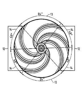
Figure 5 shows a plan view of the impeller 2 according
to the illustration in figure 4. The spacing 13 between
the bundles 12 has an angle of the blade separation of
84 . The spacing 14 of the blades 7 within the bundles
12 has an angle of the blade separation of 48 . The
angles of the blade separation between the bundles are
thus larger than the angles of the blade separation
within the bundles 12 by a factor of 1.75.
Consequently, the angles of the blade separation
between the bundles 12 are not an integer multiple of
the angles of the blade separation within the bundles
12.
Figure 6 shows a view into the non-chokable pump, in
which an impeller 2 is arranged in the pump casing part
15. The casing is a volute casing. The solids-
containing medium exits the non-chokable pump through a
discharge connector 17.
Figure 7 shows the impeller 2 according to the
illustration in figure 6 with a section line A-A. A
section along this line A-A is illustrated in figure 8.
The height h of the blades 7 decreases in the radial
CA 02910990 2017-1.2-28
WO 2017/001340 PCT/EP2016/064855
- 9 -
direction, that is to say toward the impeller outer
diameter. The decrease is in relation to a reference
plane 16, which is partially illustrated by dashed
lines in figure 8. In the exemplary embodiment, the
decrease occurs at a bevel angle a of 50
.
Figure 8 shows a ball 18 in an upper and a lower
position. The ball 18 has a diameter d and a radius a.
According to the lower position of the ball 18, the
ball 18 dips by a depth b into the spaces of the
impeller 2 between the bundles 12. This dipping segment
of the ball has a secant c.
Due to arrangement according to the invention of the
blades 7 in bundles 12, it is possible for a ball which
has a diameter d which corresponds to the diameter of
the suction mouth D to dip by a depth b into the spaces
between the bundles 12. This allows the spacing A of
the blade front to the suction-side casing wall 11 to
be reduced in comparison with the diameter d by this
depth b, with the result that the non-chokable pump has
higher efficiency and still ensures the maximum ball
passage d of the diameter D of the suction mouth 10.
The following relationship exists between the spacing
A, the depth b and the diameter D:
A + b = D (formula 1).
The depth can be calculated as follows:
b - a -11a2 -(c)2 (formula 2).
2