Note: Descriptions are shown in the official language in which they were submitted.
CA 02991319 2018-01-03
WO 2017/007933 PCT/US2016/041333
LED PANEL LIGHTING SYSTEM
CROSS-REFERENCE TO RELATED APPLICATIONS
[0001] This application claims the benefit of U.S. Provisional Patent
Application No. 62/190,163
filed on July 8, 2015, entitled "LED Panel Lighting System," and U.S.
Provisional Patent
Application No. 62/193,020 filed on July 15, 2015, entitled "LED Panel
Lighting System," each
of which is incorporated by reference herein in its entirety.
FIELD OF THE TECHNOLOGY
[0002] The technology generally relates to light emitting diode (LED) lighting
systems, and in
particular to LED panel lighting systems with improved light extraction
efficiency, light quality,
and design flexibility.
BACKGROUND OF THE TECHNOLOGY
[0003] Panel lighting systems for residential and commercial applications have
increasingly
utilized LEDs as a light source due to their high lumen output, decreased
energy consumption,
and extended life cycle compared to traditional light sources such as
fluorescent or incandescent
light bulbs. Conventional edge-lit LED panel lighting systems generally
include a frame in
which white LEDs emit light into the edge of a light guide having features to
distribute and emit
light for illuminating a room, corridor, or other area. The need for maximum
utilization of energy
drives the design of components and features that reduce optical losses.
[0004] Currently white LEDs are obtained through the down-conversion of a
fraction of the blue
light emitted from a blue LED chip to produce yellow light, which upon mixing
with the
remaining (unconverted) blue light yields a spectrum that appears white to the
human eye.
CA 02991319 2018-01-03
WO 2017/007933 PCT/US2016/041333
Conventional white LEDs typically use a coating containing one or more rare-
earth-containing
phosphors to realize such a color conversion.
[0005] However, the conventional implementation suffers from a variety of
problems, including
far-field color non-uniformity originating from poor control of phosphor
dispersion, significantly
reduced external quantum efficiency due to phosphor quenching and unfavorable
scattering
losses, poor color rendition capability of saturated red hues (termed R9), and
high material cost
at the required phosphor loading level, as well as high binning costs when the
lighting
application has a tight tolerance for color quality variations.
SUMMARY OF THE TECHNOLOGY
[0006] In an embodiment a lighting device includes a frame having a first
edge; at least one light
emitting diode and coupled to an interior of a second edge of the frame; a
light guide panel
positioned in the frame, an edge of the light guide panel in communication
with the at least one
light emitting diode; at least one reflective sheet coupled to a rear surface
of the light guide
panel; and at least one color conversion sheet coupled to a front surface of
the light guide panel.
In some embodiments the at least one light emitting diode includes a flat-top
lens (and/or may
exclude a domed lens). The light emitting diode may emit blue light. The at
least one color
conversion sheet may be configured to convert the blue light emitted by the at
least one light
emitting diode to a white light. The lighting device may further include a
power supply coupled
to the frame, the power supply providing power to the at least one light
emitting diode, and in
some cases may further include a dimming control coupled to the at least one
light emitting
diode and/or a proximity sensor and/or a light sensor coupled to one or more
of the power supply
and the dimming control. In some embodiments the lighting device may include a
diffuser,
which in some cases may be coupled to a front surface of the color conversion
sheet. The
2
CA 02991319 2018-01-03
WO 2017/007933 PCT/US2016/041333
lighting device may further include a reflective strip that is in
communication with an edge of the
light guide panel, wherein the edge of the light guide pane that is in
communication with the
reflective strip is not in communication with the blue light emitting diode.
[0007] In some embodiments the color conversion sheet comprises a first layer
and a second
layer, wherein the first layer comprises a first dye and the second layer
comprises a second dye.
The first dye may be configured to absorb light emitted by the at least one
light emitting diode
and the second dye may be configured to absorb light emitted by the first dye.
In some
embodiments, the first dye and second dye are each independently selected from
the group
consisting of rylenes, xanthenes, porphyrins, and phthalocyanines. In
particular, in some
embodiments the first dye and the second dye are each independently selected
from the group
consisting of 3-cyanoperylene-9,10-dicarboxylic acid 2',6'-
diiosopropylanilide, 3,4,9,10-perylene
tetracarboxylic acid bis(2,6-diisopropyl) anilide, 1,6,7,12-tetraphenoxy-N,N'-
di(2,6-
diisopropylpheny1)-3,4:9,10-perylenediimide, Rhodamine B, Eosin Y,
fluorescein, 5,10,15,20-
tetrapheny1-21H,23H-tetraphenylporphine, and 2,3,7,8,12,13,17,18-octaethy1-
21H,23H-
porphine. In specific embodiments the yellow light emitting dye includes 3-
cyanoperylene-9,10-
dicarboxylic acid 2'6'-diisopropylanilide. In specific embodiments the green
light emitting dye
comprises diisobutyl 4,10-dicyanoperylene-3,9-dicarboxylate. In specific
embodiments the red
light emitting dye comprises 1,6,7,12-tetraphenoxy-N-N'-di(2,6-
diisopropylpheny1)-3,4:9,10-
perylenediimide. In some embodiments the second layer comprises a yellow light
emitting dye
and the first layer comprises at least one of a green light emitting dye and a
red light emitting
dye. The second layer may be positioned between the first layer and the light
guide panel.
[0008] In some embodiments a lighting device includes any or all of the
features described
above and further includes at least one light injection optic coupled to the
at least one light
3
CA 02991319 2018-01-03
WO 2017/007933 PCT/US2016/041333
emitting diode and the edge of the light guide panel, the at least one light
injection optic
configured to direct a first light emitted from the at least one light
emitting diode into the edge of
the light guide panel. The at least one light injection optic has a focal
point and, in some
embodiments, the at least one light emitting diode is positioned at the focal
point of the at least
one light injection optic. The at least one light injection optic may include
a lens or a mirror. In
some embodiments the at least one light injection optic is a mirror having a
pyramidal structure
having a base, which may be oriented parallel to the second edge of the frame.
In some
embodiments the at least one light injection optic is a mirror having a
conical structure having a
base. In some embodiments the at least one light injection optic comprises an
array of light
injection optics. In some embodiments where the at least one light injection
optic comprises an
array of light injection optics, the at least one light emitting diode
includes a plurality of light
emitting diodes, wherein the array of light injection optics comprises a light
injection optic for
each of the plurality of blue light emitting diodes. In other embodiments the
at least one light
injection optic consists of a single light injection optic having a base that
extends a length of the
second edge of the frame.
[0009] In some embodiments a lighting device includes any or all of the
features described
above and further includes a driver configured to modulate intensity of a
light emitted from the
lighting device at a rate of about 20 to about 70 MHz. In such embodiments the
at least one color
conversion sheet may include a dye having a fluorescence lifetime of about 5
ns or less. Such a
lighting device may be configured to function as a wireless communication
device.
[0010] In some embodiments a lighting device includes any or all of the
features described
above and further includes a color neutralization device for neutralizing a
color of the at least one
color conversion sheet.
4
CA 02991319 2018-01-03
WO 2017/007933 PCT/US2016/041333
[0011] The color neutralization device may be configured to reduce an amount
of ambient light
interacting with the at least one color conversion sheet. In such embodiments,
the color
neutralization device may comprise a shutter. In a specific embodiment, the
color neutralization
device may further comprise a power source, wherein the shutter is in
electronic communication
with the power source and is configured to mechanically close in response to
the power source
not providing power. In another specific embodiment, the color neutralization
device may further
comprise a power source, wherein the shutter is in electronic communication
with the power
source and is configured to appear opaque in response to a power source not
providing power.
[0012] The color neutralization device may be configured to reduce the amount
of converted
yellow light emitted from a front surface of the lighting device. In such
embodiments, the color
neutralization device may comprise a gasket configured to provide an air gap
between one or
more of the at least one color conversion sheet and the light guide panel, the
light guide panel
and the at least one reflective sheet, and a diffuser and the at least one
color conversion sheet. In
other embodiments where the color neutralization device is configured to
reduce the amount of
converted yellow light emitted from a front surface of the lighting device,
the color
neutralization device includes an electrophoretic display configured to change
a color of the at
least one reflective sheet. In still other embodiments the color
neutralization device is configured
to redirect converted yellow light away from a line of sight of a viewer. For
example, the color
neutralization device may include at least one light direction control optic
configured to direct
ambient light reflected from the at least one color conversion sheet at an
angle substantially
greater than an angle of dispersion of light emitted from the lighting device.
[0013] The color neutralization device may be configured to provide additional
blue light to
neutralize a yellow color of the lighting device when the at least one light
emitting diode is off.
CA 02991319 2018-01-03
WO 2017/007933 PCT/US2016/041333
In such an embodiment, the color neutralization device may include a power
limiting circuit or
limited power source configured to limit the power provided to the at least
one light emitting
diode from one or more of a battery and a second power supply. A power
limiting circuit or
limited power source may provide sufficient power to the at least one light
emitting diode to
stimulate emission of white light from a photoluminescent component in the at
least one color
conversion sheet sufficient to neutralize a color of the at least one color
conversion sheet.
[0014] In some embodiments a lighting device includes any or all of the
features described
above and further includes, wherein the first edge comprises an access panel.
In some
embodiments a lighting device may further comprise a hinge connecting the
access panel to the
frame, while in other embodiments the access panel comprises one or more
removable fasteners
connecting the access panel to the frame, or both one or more removable
fasteners connecting the
access panel to the frame and a hinge connecting the second edge to the frame.
In some
embodiments wherein the first edge comprises an access panel, one or more of
the light guide
panel, the at least one reflective sheet, and the at least one color
conversion sheet may be
configured to be removed from the lighting device via the access panel without
otherwise
disassembling the frame.
[0015] In some embodiments a lighting device includes any or all of the
features described
above and may further include a stability enhancement layer. In some
embodiments the stability
enhancement layer may include polyvinyl alcohol, ethylene vinyl alcohol
copolymers, polyvinyl
chloride, polyyinylidene chloride copolyiners (saran), nylons, acrylonitril
es, polyethylene
terephthalate polyester, polyethylene naphthalate, polytrimethyl
terephthalate, liquid crystal
polymers, transparent inorganic oxide coatings, nanocoinposites, oxygen
scavengers, aromatic
polyketones and any combinations or blends thereof. In some embodiments the
stability
6
CA 02991319 2018-01-03
WO 2017/007933 PCT/US2016/041333
enhancement layer may comprise a singlet oxygen quencher. In some embodiments
the color
conversion sheet may comprise a singlet oxygen quencher. A singlet oxygen
quencher for use in
a stability enhancement layer and/or a color conversion sheet may include
2,2,6,6-tetrametliy1-4-
piperidone, 1,4-diazabicyclo[2.2.2]octane, or diphenylsultide
[0016] In some embodiments a lighting device includes any or all of the
features described
above and may be used for an audio device, which may include a speaker. In
such embodiments,
the light guide panel may define a light guide panel hole, and/or the at least
one color conversion
sheet may define a color conversion sheet hole, wherein the light guide panel
and/or the at least
one color conversion sheet are positioned such that the light guide panel hole
and/or the color
conversion sheet hole are aligned with the speaker. The lighting device for an
audio device may
further include an acoustic scrim. The lighting device for an audio device may
further include a
first layer of a first ink, wherein the first ink comprises a first
photoluminescent dye. The first
layer of the first ink may define an image or pattern. The first layer of the
first ink may be
adhered to the at least one color conversion sheet; alternatively, the first
layer of the first ink may
be adhered to the acoustic scrim.
[0017] In an embodiment, a method of making an edge-lit light emitting diode
sign includes:
providing: a frame having a first edge; at least one blue light emitting diode
coupled to an
interior of a second edge of the frame; a light guide panel positioned in the
frame, an edge of the
light guide panel in communication with the at least one blue light emitting
diode; at least one
reflective sheet coupled to a rear surface of the light guide panel; and at
least one color
conversion sheet coupled to a front surface of the light guide panel; and
printing an image on the
at least one color conversion sheet with an ink comprising a photoluminescent
dye.
7
CA 02991319 2018-01-03
WO 2017/007933 PCT/US2016/041333
[0018] Embodiments of the technology described herein are directed to LED
panel lighting
systems including features that overcome deficiencies of conventional LED
panel lighting
systems.
[0019] In one aspect, the technology relates to a lighting device including
various combinations
of features. The lighting devices can includes a frame having a first edge
with an access panel
and at least one light emitting diode coupled to an interior of a second edge
of the frame. The
lighting device can further include a light guide panel positioned in the
frame. An edge of the
light guide panel is in communication with the at least one light emitting
diode. The lighting
device can further include at least one light injection optic coupled to the
at least one light
emitting diode and the edge of the light guide panel. The at least one light
injection optic is
configured to direct a first light emitted from the at least one light
emitting diode toward the edge
of the light guide panel. The lighting device can further include at least one
reflector coupled to
the at least one light emitting diode. The at least one reflector is
configured to direct a second
light emitted from the at least one light emitting diode toward the edge of
the light guide panel.
The lighting device can further include at least one reflective sheet coupled
to a rear surface of
the light guide panel and at least one color conversion sheet coupled to a
front surface of the light
guide panel. The lighting device can further include a cover coupled to a rear
of the frame.
[0020] In some embodiments, the lighting device further includes various
combinations of
features. The lighting device can include a power supply coupled to the frame.
The power
supply provides power to the at least one light emitting diode. The lighting
device can further
include a dimming control coupled to the at least one light emitting diode.
The lighting device
can further include a proximity sensor coupled to one or more of the power
supply and the
dimming control. The lighting device can further include a wireless
communication device
8
CA 02991319 2018-01-03
WO 2017/007933 PCT/US2016/041333
coupled to one or more of the frame, the power supply, the dimming control,
and the proximity
sensor. The wireless communication device is configured to communicate with
one or more of a
remote lighting controller and a wireless communications device of a second
lighting device.
The lighting device can further include a color neutralization device for
neutralizing a color of
the at least one color conversion sheet. The color neutralization device can
include one or more
of (i) a power limiting circuit or a limited power source configured to affect
the off-state color by
providing power to the at least one light emitting diode from a battery or
second power supply,
(ii) a closeable shutter configured to conceal the at least one color
conversion sheet, (iii) a gasket
configured to provide an air gap between one or more of the color conversion
sheet and the light
guide panel, the light guide panel and the reflective sheet, and a diffuser
and the color conversion
sheet, (iv) at least one light direction control optic configured to direct a
third light (e.g., an
ambient light) reflected from the color conversion sheet at an angle
substantially greater than a
viewing angle of light emitted from the system, and (v) an electrophoretic
display configured to
change a color of the reflective sheet.
[0021] In some embodiments, the lighting device is configured to provide light
for illuminating
the premises of a commercial building. In some embodiments, the lighting
device is configured
for replacing or retrofitting an existing lighting device based on an
incandescent, fluorescent, or
halogen light source. In some embodiments, the lighting device can be
configured to provide
graphical or image display as for signage. In some embodiments, the lighting
device is
configured to provide surface illumination, including graphical or image
display, for an
acoustical system. In some embodiments, the lighting device is configured as a
fixture for
providing light to an interior of an automobile. In some embodiments the
lighting device is
configured as a fixture for providing light to an interior of a boat or other
transportation vehicle.
9
CA 02991319 2018-01-03
WO 2017/007933 PCT/US2016/041333
[0022] Other aspects of the technology will become apparent from the following
detailed
description, taken in conjunction with the accompanying drawings, illustrating
the principles of
the technology by way of example only.
BRIEF DESCRIPTION OF THE DRAWINGS
[0023] The foregoing and other objects, features, and advantages of the
presently-described
technology as well as the technology itself, will be more fully understood
from the follow
description of various embodiments, when read together with the accompanying
drawings.
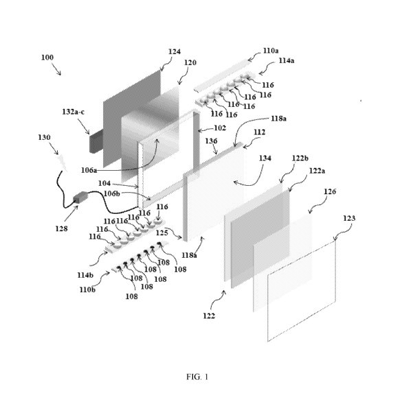
[0024] FIG. 1 is an exploded perspective view of an LED panel lighting system
according to
embodiments of the technology described herein.
[0025] FIG. 2A is an exploded side perspective view of an LED panel lighting
system showing a
closeable access panel feature according to embodiments of the technology
described herein.
[0026] FIG. 2B is an exploded side perspective view of an LED panel lighting
system showing a
closeable access panel feature according to embodiments of the technology
described herein.
[0027] FIG. 2C is an exploded side perspective view of an LED panel lighting
system showing a
closeable access panel feature according to embodiments of the technology
described herein.
[0028] FIG. 2D is an exploded side perspective view of an LED panel lighting
system showing a
closeable access panel feature according to embodiments of the technology
described herein.
[0029] FIG. 3A is a perspective view of a v-groove reflector for reflecting
light emitted by an
LED according to embodiments of the technology described herein.
[0030] FIG. 3B is a perspective view of a parabolic reflector for reflecting
light emitted by an
LED according to embodiments of the technology described herein.
[0031] FIG. 3C is a side view of a truncated v-groove reflector for reflecting
light emitted by an
LED according to embodiments of the technology described herein.
CA 02991319 2018-01-03
WO 2017/007933 PCT/US2016/041333
[0032] FIG. 4A illustrates the normalized spectral power distribution by
wavelength in nm of the
absorption spectrum (dashed line) and the radiation spectrum in (solid line)
for a yellow
luminescent dye.
[0033] FIG. 4B illustrates the normalized spectral power distribution by
wavelength in nm of the
absorption spectrum in dashed lines and the radiation spectrum in solid line
for a red luminescent
dye.
[0034] FIG. 4C illustrates the normalized spectral power distribution by
wavelength in nm of the
absorption spectrum in dashed lines and the radiation spectrum in solid line
for a green
luminescent dye.
[0035] FIG. 4D illustrates the normalized spectral power distribution by
wavelength in nm of the
radiation spectrum in solid line for a blue light emitting diode.
[0036] FIG. 4E is a side view of a lighting panel system in accordance with an
embodiment of
the invention.
[0037] FIG. 5 is an exploded side cut-away view of a speaker including a
lighting panel system
in accordance with an embodiment of the invention.
[0038] FIG. 6A is a side view of a domed LED in relation with the edge of a
light guide panel.
[0039] FIG. 6B is a graph illustrating the normalized radiative intensity vs.
radiation angle for a
flat-lens light emitting diode.
[0040] FIG. 6C is a side view of a flat-lens LED.
[0041] FIG. 6D is a side view of a domed lens LED.
DETAILED DESCRIPTION
[0042] The technology described herein relates to LED panel lighting systems
and applications
thereof. Using the components and configurations described below, an LED panel
lighting
11
CA 02991319 2018-01-03
WO 2017/007933 PCT/US2016/041333
system can be constructed to accommodate a wide variety of lighting system
applications. For
example, the LED panel lighting system can be configured for use in large form
factor lighting
systems (e.g., lighted billboards, commercial lighting), as well as small form
factor lighting
systems (e.g., retrofit lamps, automotive interior lighting).
[0043] FIG. 1 is an exploded perspective view of an LED panel lighting system
100 ("system
100") according to embodiments of the technology described herein. System 100
includes a
fixture frame 102 for housing and/or mounting the various components of system
100 and a
cover 124 coupled to the rear of fixture frame 102 to secure the various
components of system
100 in fixture frame 102.
[0044] Fixture frame 102 can include features for mounting the components of
system 100. For
example, the interior edges of fixture frame 102 can include grooves or other
features configured
to position the various components of system 100 within fixture frame 102.
Fixture frame 102
can be any LED panel frame or lightbox known in the art. In some embodiments,
fixture frame
102 is a rectangular frame having four planar edges.
[0045] Cover 124 can be a metal or plastic panel with tabs or other attachment
features for
coupling cover 124 to fixture frame 102. In some embodiments, cover 124
includes mounting
features to facilitate securing system 100 to a surface such as a ceiling or
wall.
[0046] In some embodiments, fixture frame 102 includes an access panel 104
configured to
enable access to the components of system 100 mounted inside of fixture frame
102. Access
panel 104 is discussed in more detail below with respect to FIGS. 2A-2E.
[0047] System 100 further includes at least one LED 108 as a light source, and
power supply
128 for providing power to the at least one LED 108 in addition to other
components of system
100 discussed below. Power supply 128 can be any power converter for
converting a line
12
CA 02991319 2018-01-03
WO 2017/007933 PCT/US2016/041333
voltage 130 to a DC voltage that can be used to power the components of system
100. In some
embodiments, line voltage 130 is an AC power source, and power supply 128 is
an AC to DC
converter. In some embodiments, line voltage 130 is a DC power source, and
power supply 128
is a DC to DC converter.
[0048] LED 108 can be a blue LED that emits light having a wavelength
substantially in the
range of 440-495nm. In some embodiments, at least one LED 108 is mounted to a
carrier such
as a rigid, flexible, or semi-flexible printed circuit board to form an LED
strip that can be
mounted to an interior edge of fixture frame 102. For example, as shown in
FIG. 1, LED strip
110b includes seven LEDs 108 arranged in a single row with a fixed distance
between each LED
108. (LED strip 110a likewise includes seven LEDs 108, however the perspective
angle of FIG.
1 shields them from view.) It should be appreciated that any number and/or
color of LEDs,
arranged on a variety of carriers in a variety of circuit configurations
(e.g., series-connected
LEDs, parallel-connected LEDs) can be used without departing from the scope of
the
technology.
[0049] In some embodiments LED 108 comprises a lens, such as a domed lens or a
flat lens.
Preferably, LED 108 comprises a flat-top lens. A domed lens in LED 108 may
interfere with the
ability to inject light from the LED into a light guide panel 112. For
example, a wider angle of
divergence of light emitted from the LED requires a shorter preferable
distance between the LED
108 and the light guide panel 112, in order to maximize the number of photons
emitted from the
LED 108 and injected into the light guide panel 112. A domed lens may limit
the number of
photons that can be injected into the light guide panel by limiting the
proximity between the LED
108 and the light guide panel 112. In some embodiments LED 108 comprises a
flat-top lens and
the lighting device 100 is configured to obtain greater than 90% efficiency of
capture of light
13
CA 02991319 2018-01-03
WO 2017/007933 PCT/US2016/041333
emitted from the LED 108 into the light guide panel 112. In some embodiments
LED 108
comprises a flat-top lens and the lighting device 100 is configured to obtain
greater than 70%
efficiency of capture of light emitted from the LED 108 into the light guide
panel 112.
[0050] The efficiency of the capture of light into light guide panel 112 may
depend on
characteristics of LED 108 (e.g. the angle of dispersion of light emitted) as
well the
configuration of LED 108 and light guide panel 112 (e.g. the ratio of the
distance between LED
108 and light guide panel 112 to the thickness of the light guide panel 112).
In some
embodiments system 100 can achieve greater than 90% efficiency of capture of
light emitted
from the LED 108 into the light guide panel 112 where the ratio of the
distance between the LED
108 and the light guide panel 112 to the thickness (i.e. width of the edge) of
the light guide panel
112 is no greater than 1:10, no greater than 1:8, no greater than 1:6, no
greater than 1:5, or no
greater than 1:4. In some such embodiments LED 108 may include a flat-top
lens. In some
embodiments the system 100 is configured to obtain greater than 70% efficiency
of capture of
light emitted from the LED 108 into the light guide panel 112, where the ratio
of the distance
between the LED 108 and the light guide panel 112 to the thickness (i.e. width
of the edge) of
the light guide panel 112 is no greater no greater than 1:6, no greater than
1:5, or no greater than
1:4, no greater than 1:3, no greater than 1:2.5, or no greater than 1:2. In
some such embodiments
LED 108 may include a flat-top lens.
[0051] LED strips 110 can be mounted to an interior edge of fixture frame 102.
For example,
LED strip 110a can be mounted to interior edge 106a of fixture frame 102.
Likewise, LED strip
110b can be mounted to interior edge 106b of fixture frame 102.
[0052] System 100 further includes light guide panel 112, color conversion
sheet 122, and
reflective sheet 120 mounted inside fixture frame 102, with color conversion
sheet 122 disposed
14
CA 02991319 2018-01-03
WO 2017/007933 PCT/US2016/041333
in front of light guide panel 112, and reflective sheet 120 disposed behind
light guide panel 112,
where front refers to a position closer to an end viewer, or the direction in
which light emittance
is maximized, and behind refers to a position farther from an end viewer and
opposed to the
front.
[0053] Light guide panel 112 is a rectangular panel formed of a transparent or
translucent
material such as acrylic configured to distribute and emit light emitted by
LEDs 108. For
example, light guide panel 112 is positioned in fixture frame 102 such that
edge 118a is
substantially adjacent to the light emitted by LEDs 108 of LED strip 110a, and
edge 118b is
substantially adjacent to the light emitted by LEDs 108 of LED strip 110b.
Light emitted from
LEDs 108 enters edges 118 and is distributed throughout light guide panel 112.
The light guide
panel 112 typically incorporates a pattern of features designed to scatter
guided optical modes of
light transmission such that they are emitted from a front face 134 of light
guide panel 112 to
provide illumination. In some embodiments, a pattern of features is provided
by surface
deformation, such as etching. In other embodiments, a pattern of features is
provided by
embossing, molding, or otherwise including discrete prismatic structures
within the light guide
panel 112. In still other embodiments, a pattern of features is provided by
printing a thin layer of
coating material onto the desired areas of the light guide panel 112. The
coating material may
have substantially the same refractive index as the light guide panel 112 and
one or more light
scattering materials substantially dispersed therein.
[0054] Reflective sheet 120 is formed of a reflective film or foil, and
redirects any light emitted
from a rear face 136 of light guide panel 112 toward front face 134. An
intimate contact between
the reflective sheet 120 and the back surface of light guide panel 112 (side
farther from viewer)
is preferred. The reflective sheet 120 can be attached to the back surface of
the light guide panel
CA 02991319 2018-01-03
WO 2017/007933 PCT/US2016/041333
112 by applying a thin and/or fine line of non-absorbing adhesive running
along the
circumference of the back surface of the light guide panel 112. The adhesive
should be selected
to not interfere with light guide panel extraction patterns.
[0055] In embodiments where at least one edge of the light guide panel 112 is
not in
communication with one or more LEDs 108, an edge reflective strip 125 can be
attached to or in
communication with an edge of the light guide panel 112 where no LEDs 108 are
distributed.
This reflective strip may prevent photons propagating within the light guide
panel 112 from
escaping from the edges where no LEDs 108 are distributed. Edge reflective
strip 125 is formed
of a reflective film or foil.
[0056] In some embodiments, at least one light injection optic 116 is
positioned between LED
108 and an edge 118 of light guide panel 112 to direct light emitted from LED
108 into light
guide panel 112 more efficiently than in conventional LED panel lighting
systems. For example,
light injection optic 116 can be a cylindrical lens or other refractive optic
capable of directing
light emitted by LED 108 into light guide panel 112 at angles that facilitate
the light being
guided out of front face 134 rather than escaping near an edge of light guide
panel 112. In some
embodiments light injection optic 116 directs light emitted by LED 108 into
light guide panel
112 by collimating or focusing light emitted by LED 108 into light guide panel
112.
[0057] In some embodiments, at least one light injection optic 116 is mounted
to a carrier to
form a light injection strip 114 that can be respectively mounted between LED
strip 110 and
edge 118 of light guide 112. As shown in FIG. 1, light injection strip 114a
includes seven light
injection optics 116 arranged in a single row with a fixed distance between
each light injection
optic 116. The fixed distance between each light injection optic 116 is chosen
to substantially
align one light injection optic 116 with each LED 108 of an LED strip 110. In
some
16
CA 02991319 2018-01-03
WO 2017/007933 PCT/US2016/041333
embodiments the light injection optics 116 are molded into edges 118 of light
guide panel 112.
Alternatively, such a light injection optic 116 can be designed as a lens
(e.g. a cylindrical lens)
that acts on two or more LEDs. In still another embodiment, such a light
injection optic 116 can
be designed as a single lens (e.g. a cylindrical lens) that acts collectively
on the array of LEDs
108 arranged near the edge of the light guide 112 to inject light from the
LEDs into the light
guide 112.
[0058] In some embodiments, the use of a light injection optic 116 comprising
a refractive
optical component between LEDs and the edge 118 of light guide panel 112 may
increase the
distance between the LED and the edge 118 of the light guide panel 112. In
such embodiments,
whether or not the refractive optical component should be included can be
determined by
considering the angle of dispersion of the primary light emission from the
LEDs. If the angle of
dispersion of the LEDs is sufficiently acute, e.g., about 160 or less, about
140 or less, about
120 or less, or about 100 or less, a smaller distance between the LEDs and
edge of the light
guide is preferred, such that no refractive optical component would be
positioned between the
LED and the edge of the light guide panel. In some embodiments the preferred
distance between
the LED and the edge of the light guide is about 10 mm or less, about 5 mm or
less, about 2 mm
or less, about 1 mm or less, about 0.75 mm or less, about 0.5 mm or less,
about 0.25 mm or less.
about 0.1 mm or less, or about 0.05 mm or less. In some embodiments the
preferred distance
between the LED and the edge of the light guide is about 0.1 mm to about 5 mm,
about 0.1 mm
to about 2 mm, about 0.1 mm to about 1 mm, about 0.01 mm to about 1 mm, about
0.01 mm to
about 0.05 mm, or about 0.01 mm to about 0.1 mm.
[0059] System 100 can include components for improving the light output of
system 100 by
increasing the number of light photons emitted from LEDs 108 that are injected
into light guide
17
CA 02991319 2018-01-03
WO 2017/007933 PCT/US2016/041333
panel 112 and ultimately collected and converted by color conversion sheet
122. For example, a
reflector can be positioned behind (e.g., underneath) and around each of LED
strips 110 to
collect light, including both primary light from LEDs 108 and secondary light
arising from light
scattering/reflection from optical surfaces, that would otherwise be lost from
being outside of the
entrance pupil to light guide panel 112 or due to back-reflection from the
entrance edge of light
guide panel 112, and instead direct this light into light guide panel 112 at
angles that benefit total
internal reflection of the injected light.
[0060] FIG. 3A is a perspective view of a v-groove reflector 302 for
reflecting light emitted by
LEDs 108 according to embodiments of the technology described herein. As shown
in FIG. 3A,
LED strip 110 is positioned at or near vertex 304 such that the reflective
surfaces of v-groove
reflector 302 are positioned substantially behind and around the LEDs 108 of
LED strip 110.
Accordingly, the reflective surfaces of v-groove reflector 302 direct light
photons emitted from
the bottom and sides of LEDs 108 substantially toward edge 118 of light guide
panel 112, which
is positioned adjacent to LEDs 108 as described above. In embodiments of
system 100 including
at least one light injection optic 116, the reflective surfaces of v-groove
reflector 302 direct light
photons emitted from the bottom and sides of LEDs 108 substantially toward the
at least one
light injection optic 116. V-groove reflector 302 can have a first arm 302a
and a second arm
302b with an angle a between the first arm 302a and second arm 302b of about
450, about 50 ,
about 55 , about 60 , about 65 , about 70 , about 75 , about 80 , about 85 ,
about 90 , about
95 , about 100 , about 105 , about 110 , about 115 , about 120 , about 125 ,
about 130 , about
135 , or about 140 . V-groove reflector 302 can have a first arm 302a and a
second arm 302b
with an angle a between the first arm 302a and second arm 302b in a range of
about 45 to about
60 , about 55 to about 70 , about 60 to about 75 , about 70 to about 85 ,
about 75 to about
18
CA 02991319 2018-01-03
WO 2017/007933 PCT/US2016/041333
90 , about 80 to about 95 , about 90 to about 105 , about 95 to about 110 ,
about 105 to
about 120 , about 110 to about 125 , about 120 to about 135 , or about 125
to about 140 . In
some embodiments a single v-groove reflector 302 is provided for LED strip
110. In some
embodiments individual v-groove reflectors 302 are provided for each of LEDs
108. In some
embodiments LED 108 or LED strip 110 is placed at the vertex of v-groove
reflector 302.
[0061] In cases where the use of an optical reflector positioned between or
extending between
LEDs 108 and the edge 118 of the light guide panel 112 increases the distance
between LED 108
and the edge 118 of the light guide panel 112, whether or not the optical
reflector should be
included can be determined as described above for an optical refractive
optical component. That
is, whether or not a light injection component 116 comprising a reflector that
is positioned or
extends between LED 108 and the edge 118 of light guide panel 112 should be
included can be
determined by considering the angle of dispersion of the primary light
emission from the LEDs
108. If the angle of dispersion of the LEDs 108 is sufficiently acute, e.g.
about 160 or less,
where angle of dispersion is, two times the off-axis angle where the LED's
luminous intensity is
half the intensity at direct on-axis view, about 140 or less, about 120 or
less, or about 100 or
less, a smaller distance between the LEDs 108 and edge 118 of the light guide
panel 112 is
preferred, such that no reflective optical component would be positioned or
extend between the
LED and the edge of the light guide panel.
[0062] In some embodiments LED strip 110 is positioned at vertex 304; however
in other
embodiments v-groove reflector 302 does not extend to a vertex, but rather
forms a truncated
prism, as shown in Fig. 3C. As shown in Fig. 3C, in some embodiments the
truncated v-groove
reflector 302 can be described as having a maximum width, d, defined by the
width of the light
guide panel 112 and a minimum width, L, defined by the width of LED 108. Since
the reflector
19
CA 02991319 2018-01-03
WO 2017/007933 PCT/US2016/041333
should ideally intersect the edges of the LED 108 and the light guide panel
112, the distance of
the LED, h', relative to the total height of the truncated groove reflector
304, h, is defined by the
ratio of the width of LED 108, L, to the width of the light guide panel 112,
d:
1006311/2 L/x = 1/2 dlh= tan 0
[0064] Such that
[0065] L/d= xlh= (h-h)lh
[0066] Or, rearranging,
[0067] h'Ih = 1 -(Lid).
[0068] In some embodiments, the v-groove reflector 302 may be designed as
isolated elements
and inject light from each emitter individually, with a single v-groove
reflector corresponding to
a single LED. In such embodiments each reflector can have a pyramidal
structure, with the base
of the pyramid aligning with the edge of the light guide. In some embodiments
adjacent
pyramidal v-groove reflectors would share an edge of their bases, as shown for
light injection
optic 116 in FIG. 1.
[0069] FIG. 3B is a perspective view of a parabolic reflector 306 for
reflecting light emitted by
an LEDs 108 according to embodiments of the technology described herein. As
shown in FIG.
3B, LED strip 110 is positioned at or near vertex 308 such that the reflective
surfaces of
parabolic reflector 306 are positioned substantially behind and around the
LEDs 108 of LED
strip 110. Accordingly, the reflective surfaces of parabolic reflector 306
direct light photons
emitted from the bottom and sides of LEDs 108 substantially toward edge 118 of
light guide
panel 112, which is positioned adjacent to LEDs 108 as described above. In
embodiments of
system 100 including at least one light injection optic 116, the reflective
surfaces of parabolic
reflector 306 direct light photons emitted from the bottom and sides of LEDs
108 substantially
CA 02991319 2018-01-03
WO 2017/007933 PCT/US2016/041333
toward the at least one light injection optic 116. In some embodiments, the
shape of the parabola
and the distance of the LED 108 from the edge of the light guide panel 112 are
defined by the
width of the light guide panel 112, d, and the width of the LED, L.
Preferably, the parabolic
reflector 306 will intersect the edges of both the light guide panel 112 and
the LED 108.
Preferably the LED 108 is placed at the focus of the parabolic reflector 306.
Where the parabolic
reflector 306 intersects the edges of both the light guide panel 112 and the
LED 108, and where
the LED 108 is positioned at the focus of the parabolic reflector 306, the
distance of the LED
108 from the edge of the light guide, h' is given by:
[0070] h' = (d2 L2)/(4L)
[0071] In some embodiments a single parabolic reflector 306 is provided for
LED strip 110. In
some embodiments individual parabolic reflectors are provided for each of LEDs
108. In some
embodiments LED 108 or LED strip 110 is placed at the focal point of parabolic
reflector 306.
[0072] In some embodiments, the parabolic reflector 306 may be designed as
isolated elements
and inject light from each emitter individually, with a single parabolic
reflector corresponding to
a single LED. In such embodiments each reflector can have a conical structure.
[0073] The v-groove reflector 302, including the truncated v-groove reflector,
and parabolic
reflector 306 respectively shown in FIGS. 3A, 3C, and 3B can comprise
materials such as metals
or plastics, and can be formed by any of several manufacturing processes known
in the art such
as casting, injecting molding, and extrusion. In some embodiments, the
reflector is formed from
plastic that is coated in a secondary process with a material such as
aluminum, silver, metal
alloy, reflective film, or any other reflective material. In some embodiments,
the reflector is
formed from uncoated white plastic. In some embodiments, the reflector further
includes
endwalls (not shown in FIGS. 3A, FIG. 3B, and FIG. 3C).
21
CA 02991319 2018-01-03
WO 2017/007933 PCT/US2016/041333
[0074] Advantages provided by the reflectors described above can be best
illustrated by way of a
comparison between the extraction efficiency achieved by conventional LED
panel lighting
systems and the system 100 described herein. Extraction efficiency is
expressed as a percentage
according to the ratio of the radiant power of the light extracted (e.g.,
emitted) from a lighting
system (e.g., system 100) to the radiant power emitted by the lighting
system's light source (e.g.,
LEDs 108). In conventional LED panel lighting systems, the extraction
efficiency can be 80% to
as low as 30%. Based on the configuration of system 100, and the components
used to assemble
system 100 such as color conversion sheet 122, system 100 can have an
extraction efficiency
substantially greater than 80%. Further, in embodiments of system 100 that
include a reflector
such as v-groove reflector 302 and parabolic reflector 306 described above,
extraction efficiency
can be as high as 90-95%. Accordingly, the use of such reflectors allows
system 100 to consume
less power since a larger percentage of the light emitted from LEDs 108
contributes to the
radiant power output of system 100.
[0075] Color conversion sheet 122 is an energy conversion structure that can
convert light
emissions of short wavelengths, such as those emitted by electroluminescent
devices (e.g., LEDs
108), to one or more longer wavelengths. Color conversion sheet 122 is
positioned in front of
front face 134 of light guide panel 112 to convert the wavelength of the light
emitted from LEDs
108 into one or more wavelengths of light that will be emitted from system
100. For example,
color conversion sheet 122 can convert light having a substantially blue color
to light having a
substantially white color. Color conversion sheet 122 can be rendered as a
cast, coated,
injection-molded, or extruded sheet, planar or otherwise, generally including
one or more layers
comprising one or more photoluminescent (e.g. phosphorescent or fluorescent)
materials such as
organic fluorescent dyes. In some embodiments, color conversion sheet 122 is a
color
22
CA 02991319 2018-01-03
WO 2017/007933 PCT/US2016/041333
conversion structure according to embodiments described in U.S. Patent Nos.
8,415,642 and
8,664,624, the contents of which are incorporated herein by reference in their
entireties.
[0076] In some embodiments a color conversion sheet comprises a first layer
comprising or
consisting essentially of a first matrix and a first photoluminescent
material. In some
embodiments a color conversion sheet further comprises a second layer
comprising or consisting
essentially of a second matrix and a second photoluminescent material. The
first and second
matrices may comprise or consist essentially of the same material, or in some
embodiments may
comprise or consist essentially of distinct materials. The first
photoluminescent material may be
characterized by a first Stokes shift and a first radiation absorption
structure and the second
photoluminescent material may be characterized by a second Stokes shift and a
second radiation
absorption spectrum. Preferably, the second absorption spectrum at least
partially overlaps with
the first radiation spectrum.
[0077] The matrix into which the dyes are dispersed can comprise of polymers
or glasses.
Polymers are particularly useful due to the greater range of available
materials from which to
sub-select so as to form a homogeneous mixture of the photoluminescent
material and the
polymer. Acceptable polymers include acrylates, polyurethanes, polycarbonates,
polyvinyl
chlorides, silicone resins, and other common polymers. Materials with glass
transition
temperatures above the normal operating temperature of the material are
particularly useful. The
polymer matrix is preferably capable of preventing aggregation of the
photoluminescent
material, that is creating a homogeneous mixture of the photoluminescent
material and the
polymer, or a solid state solution of the photoluminescent material and
polymer.
[0078] The photoluminescent materials used in the color conversion sheet of
the lighting system
described herein are selected based on their absorption and emission
properties, with preference
23
CA 02991319 2018-01-03
WO 2017/007933 PCT/US2016/041333
given to materials with high quantum yields. Preferably, the color conversion
sheet comprises
one or more photoluminescent (e.g. phosphorescent or fluorescent, in
particular organic
fluorescent) dyes. These dyes include, but are not limited to, rylenes,
xanthenes, porphyrins,
phthalocyanines, and others with high quantum yield properties. Rylene dyes
are particularly
useful. Rylene dyes include, but are not limited to, perylene ester and
diimide materials, such as
3-cyanoperylene-9,10-dicarboxylic acid 2',6'-diiosopropylanilide, 3,4,9,10-
perylene
tetracarboxylic acid bis(2,6-diisopropyl) anilide and 1,6,7,12-tetraphenoxy-
N,N'-di(2,6-
diisopropylpheny1)-3,4:9,10-perylenediimide for example. Xanthene dyes
include, but are not
limited to, Rhodamine B, Eosin Y, and fluorescein. Porphyrins include, for
example, 5,10,15,20-
tetrapheny1-21H,23H-tetraphenylporphine and 2,3,7,8,12,13,17,18-octaethy1-
21H,23H-porphine.
[0079] In some embodiments a photoluminescent material (e.g. a phosphorescent
or fluorescent
dye) emits light having a longer wavelength than the light absorbed by the
photoluminescent
material, as illustrated in FIGS. 4A-4C. In FIGS. 4A-4C, dotted lines
represent the absorption
spectrum for a given dye and solid lines represent the emission spectrum for a
given dye. For
example, a photoluminescent (e.g. phosphorescent or fluorescent) dye may
absorb blue light (e.g.
in a range of about 450 nm to about 495 nm) and emit green light (e.g. in a
range of about 495
nm to about 570 nm), yellow light (e.g. in a range of about 570 nm to about
590 nm), orange
light (e.g. in a range of about 590 nm, to about 620 nm) and/or red light
(e.g. in a range of about
620 nm to about 750 nm). In some embodiments a photoluminescent (e.g.
phosphorescent or
fluorescent) dye may absorb green light (e.g. in a range of about 495 nm to
about 570 nm) and
emit yellow light (e.g. in a range of about 570 nm to about 590 nm), orange
light (e.g. in a range
of about 590 nm to about 620 nm), and/or red light (e.g. in a range of about
620 nm to about 750
nm). In some embodiments a photoluminescent (e.g. phosphorescent or
fluorescent) dye may
24
CA 02991319 2018-01-03
WO 2017/007933 PCT/US2016/041333
absorb yellow light (e.g. in a range of about 570 nm to about 590 nm), and
emit orange light (e.g.
in a range of about 590 nm to about 620 nm) and/or red light (e.g. in a range
of about 620 nm to
about 750 nm). In some embodiments a photoluminescent (e.g. phosphorescent or
fluorescent)
dye may absorb orange light (e.g. in a range of about 590 nm to about 620 nm)
and emit red light
(e.g. in a range of about 620 nm to about 750 nm).
[0080] In some embodiments a photoluminescent (e.g. phosphorescent or
fluorescent) dye may
have an absorption spectrum that such that the photoluminescent (e.g.
phosphorescent or
fluorescent) dye can absorb more than one color of light. For example, in some
embodiments a
photoluminescent (e.g. phosphorescent or fluorescent) dye may absorb light in
a range of from
about 380 nm to about 520 nm, about 380 nm to about 560 nm, or about 380 to
about 600 nm.
[0081] In some embodiments, it is desirable that the color conversion panel
122 and/or system
100 produce white light. The generation of white light from a blue source
entails the creation of
green, yellow, and red spectral components from the blue source. The proper
combination of
these components can lead to white light, with the quality characteristics,
such as correlated color
temperature (CCT) and color rendering index (CRI) defined by the amount of
each spectral
component included in the combined spectrum. The dyes used in these
constructions absorb
incident light and emit their fluorescence isotropically (in all directions).
These dyes do not
absorb blue light equally, but can be part of an energy cascade to shift
generally shorter
wavelengths to longer wavelengths, with each shorter wavelength emission being
absorbed, to
some extent, by a dye responsible for a longer wavelength spectral component.
For example, as
a result, green light, generated by a green-emitting dye, will have a tendency
to be absorbed by a
yellow emitter to be converted to yellow light. Such conversion will in turn
reduce the color
temperature and reduce the CRI of the emitted white light. In preferred
embodiments, color
CA 02991319 2018-01-03
WO 2017/007933 PCT/US2016/041333
quality management can be handled by separating the conversion dyes, for
example, such that
the green and red color emitters are placed in a separate layer, or such that
green and red color
emitters are placed together in a layer separate from a yellow color emitter.
In particular, it is
preferred that green and red color emitters are placed closer to the viewer
(farther from the blue
light emitting diode source), with the yellow emitting dye being placed closer
to the source. In
this way, the distribution of green light into the viewing hemisphere can be
maximized.
[0082] Accordingly, the spectrum of light emitted from the lighting device can
be controlled by
separating some or all of the photoluminescent (e.g. phosphorescent or
fluorescent) components
into separate layers, and/or separating photoluminescent (e.g. phosphorescent
or fluorescent)
components from other dyes and/or pigments that can absorb light emitted from
the light
emitting diode or other photoluminescent (e.g. phosphorescent or fluorescent)
components
within the color conversion sheet into separate layers. In some embodiments
lower wavelength
spectral components may be optimized by separating the color changing
components so that the
photoluminescent (e.g. phosphorescent or fluorescent) components (and other
dyes and/or
pigments) that absorb such lower wavelength spectral components are positioned
behind (e.g.
closer to the light guide panel 112) another layer of the color conversion
sheet 122 that contains
photoluminescent (e.g. phosphorescent or fluorescent) components that absorb
high wavelength
spectral components.
[0083] In some embodiments a first layer may comprise a first photoluminescent
material and a
second layer may comprise a second photoluminescent material, the first
photoluminescent
material having a first absorption spectrum and a first radiation spectrum,
and the second
photoluminescent material having a second absorption spectrum and a second
radiation
spectrum. Preferably, at least one of the first and second absorption spectra
at least partially
26
CA 02991319 2018-01-03
WO 2017/007933 PCT/US2016/041333
overlaps with a primary radiation spectrum of the primary emission source
(i.e. the light emitting
diode). In some embodiments both of the first and second absorption spectra at
least partially
overlap with a primary radiation spectrum of the primary emission source (i.e.
a light emitting
diode). In a specific embodiment, the second photoluminescent material has an
absorption
spectrum that at least partially overlaps with the radiation spectrum of the
first radiation
spectrum.
[0084] In some embodiments a first layer may comprise a first photoluminescent
material and a
second layer may comprise a second photoluminsecent material, the first
photoluminscent
material having a first absorption spectrum and emitting light having a first
average wavelength,
and the second photoluminescent material having a second absorption spectrum
and emitting
light having a second average wavelength. Preferably, at least one of the
first and second
absorption spectra at least partially overlaps with a primary radiation
spectrum of the primary
emission source (i.e. the light emitting diode). In some embodiments both of
the first and second
absorption spectra at least partially overlap with a primary radiation
spectrum of the primary
emission source (i.e. a light emitting diode). In some embodiments the first,
second and third
photoluminescent materials serve to shift the primary emission from the
primary light source (i.e.
the light emitting diode) to an emitted light from the lighting device,
wherein the emitted light
has a longer wavelength than the primary emission. In some embodiments the
first average
wavelength corresponds to a green color and the second average wavelength
corresponds to a
yellow, orange, or red color. In some embodiments the first average wavelength
corresponds to a
yellow color and the second average wavelength corresponds to an orange or red
color. In some
embodiments a first average wavelength corresponds to an orange color and the
second average
wavelength corresponds to a red color.
27
CA 02991319 2018-01-03
WO 2017/007933 PCT/US2016/041333
[0085] In some embodiments a first layer may comprise a first photoluminescent
material and a
second photoluminescent material, and a second layer may comprise a third
photoluminsecent
material, the first photoluminscent material having a first absorption
spectrum and a first
radiation spectrum, the second photoluminescent material having a second
absorption spectrum
and a second radiation spectrum, and the third photoluminescent material
having third absorption
spectrum and a third radiation spectrum. Preferably, at least one of the
first, second, and third
absorption spectra at least partially overlaps with a primary radiation
spectrum of the primary
emission source (i.e. the light emitting diode). In some embodiments two, or
all of the first,
second, and third absorption spectra at least partially overlaps with a
primary radiation spectrum
of the primary emission source (i.e. a light emitting diode). In a specific
embodiment, the third
photoluminescent material has an absorption spectrum that at least partially
overlaps with the
radiation spectrum of at least one of or both the first radiation spectrum and
the second radiation
spectrum. In some embodiments the second absorption spectrum may at least
partially overlap
with the first radiation spectrum.
[0086] In some embodiments a first layer may comprise a first photoluminescent
material and a
second photoluminescent material, and a second layer may comprise a third
photoluminsecent
material, the first photoluminscent material having a first absorption
spectrum and emitting light
having a first average wavelength, the second photoluminescent material having
a second
absorption spectrum and emitting light having a second average wavelength, and
the third
photoluminescent material having third absorption spectrum emitting light
having a third average
wavelength. Preferably, at least one of the first, second, and third
absorption spectra at least
partially overlaps with a primary radiation spectrum of the primary emission
source (i.e. the light
emitting diode). In some embodiments two, or all of the first, second, and
third absorption
28
CA 02991319 2018-01-03
WO 2017/007933 PCT/US2016/041333
spectra at least partially overlaps with a primary radiation spectrum of the
primary emission
source (i.e. a light emitting diode). In a specific embodiment, the third
photoluminescent material
has an absorption spectrum that at least partially overlaps with one or both
of the first and second
average wavelength. In some embodiments the second absorption spectrum may at
least partially
overlap with the first average wavelength.
[0087] In some embodiments the first, second and third photoluminescent
materials serve to shift
the primary emission from the primary light source (i.e. the light emitting
diode) to an emitted
light from the lighting device, wherein the emitted light has a longer
wavelength than the
primary emission. In some embodiments the first or second average wavelength
corresponds to a
green color and the third average wavelength corresponds to a yellow, orange,
or red color. In
some embodiments the first or second average wavelength corresponds to a
yellow color and the
third average wavelength corresponds to an orange or red color. In some
embodiments a first or
second average wavelength corresponds to an orange color and the third average
wavelength
corresponds to a red color.
[0088] In some embodiments where a color conversion sheet 122 comprises more
than one layer,
one of a first layer 122a and a second layer 122b can include dyes that emit
green light, such as
diisobutyl 4,10-dicyanoperylene-3,9-dicarboxylate, fluorescein, and Coumarin
6. In some
embodiments where a color conversion sheet 122 comprises more than one layer,
one of a first
layer 122a and a second layer 122b can include dyes that emit red light, such
as 1,6,7,12-
tetraphenoxy-N,N'-di(2,6-diisopropylpheny1)-3,4:910-perylene-diimide and
5,10,15,20-tetra(9,9-
dihexy1-9H-fluoren-2-yl)porphyrin. In some embodiments where a color
conversion sheet 122
comprises more than one layer, one of a first layer 122a and a second layer
122b can include one
or more dyes that emit green light such as diisobutyl 4,10-dicyanoperylene-3,9-
dicarboxylate,
29
CA 02991319 2018-01-03
WO 2017/007933 PCT/US2016/041333
fluorescein, and Coumarin 6, and one or more dyes that emit red light, such as
1,6,7,12-
tetraphenoxy-N,N'-di(2,6-diisopropylpheny1)-3,4:910-perylene-diimide and
5,10,15,20-tetra(9,9-
dihexy1-9H-fluoren-2-yl)porphyrin. In some embodiments where a color
conversion sheet 122
comprises more than one layer, one of a first layer 122a and a second layer
122b can include
dyes that emit yellow light, such as 3-cyanoperylene-9,10-dicarboxylic acid
2'6'-
diisopropylanilide and Eosin Y. In some embodiments where a color conversion
sheet 122
comprises more than one layer, one of a first layer 122a and a second layer
122b can include one
or more dyes that emit green light, such as diisobutyl 4,10-dicyanoperylene-
3,9-dicarboxylate,
fluorescein, and Coumarin 6, and one or more dyes that emit red light, such as
1,6,7,12-
tetraphenoxy-N,N'-di(2,6-diisopropylpheny1)-3,4:910-perylene-diimide and
5,10,15,20-tetra(9,9-
dihexy1-9H-fluoren-2-yl)porphyrin, while the other of a first layer 122a and a
second layer 122b
can include one or more dyes that emit yellow light, such as 3-cyanoperylene-
9,10-dicarboxylic
acid 2'6'-diisopropylanilide and Eosin Y. The foregoing embodiments are
provided as examples
of layering of different types of photoluminescent (e.g. phosphorescent or
fluorescent) dyes
within color changing sheet 122; other combinations of layers comprising
different dyes are
within the scope of the invention.
[0089] In a specific embodiment, a lighting device comprises a color
conversion sheet
comprising a first layer 122a comprising diisobutyl 4,10-dicyanoperylene-3,9-
dicarboxylate and
1,6,7,12-Tetraphenoxy-N,N'-di(2,6-diisopropylpheny1)-3,4:910-perylene-diimide,
and a second
layer 122b comprising 3-cyanoperylene-9,10-dicarboxylic acid 2'6'-
diisopropylanilide.
[0090] In some embodiments, color conversion sheet 122 further includes
materials to optically
scatter the light emitted into color conversion sheet 122 by light guide panel
112 and/or the
converted light that is ultimately emitted from color conversion sheet 122.
The scattering of the
CA 02991319 2018-01-03
WO 2017/007933 PCT/US2016/041333
light can increase the effective optical path length of the color conversion
sheet 122 thereby
increasing the amount of light that is absorbed and converted to a desired
wavelength. For
example, the scattering of the emitted light serves to alter the path of
emitted light rays that
would otherwise be emitted from the edges of the color conversion sheet 122
due to total internal
reflection.
[0091] Color conversion sheet 122 enables system 100 to provide distinct
advantages over
existing LED lighting systems. For example, light guide panels used for
conventional lighting
systems typically include structures such as unevenly-spaced bumps formed
within them to
uniformly extract light from the front of the light guide panel. Since these
scattering structures
can be undesirable from an aesthetic standpoint, conventional lighting
applications typically
include an additional diffuser sheet or component placed in front of the light
guide panel to
conceal the scattering structures. Color conversion sheet 122 can eliminate
the need for such an
additional diffuser panel component as the materials used to optically scatter
the light in the
color conversion sheet sufficiently diffuse the light emitted from system 100
without negatively
affecting the aesthetic appeal of system 100.
[0092] Further, due to the molecular dissolution of the organic dyes used for
color conversion
sheet 122, the light converted by color conversion sheet 122 provides a
superior color uniformity
and conversion efficiency over existing LEDs that use a rare-earth-containing
phosphor coating
to effect a color conversion. Accordingly, the superior color uniformity
provided by color
conversion sheet 122 allows LEDs having a wider binning tolerance to be used
to achieve a
desired color of light. In addition, the increased conversion efficiency
allows fewer LEDs to be
used for a given lighting application, which results in a component cost
savings, as well as a
31
CA 02991319 2018-01-03
WO 2017/007933 PCT/US2016/041333
reduction in energy consumption and thermal management challenges for a
desired lumen
output.
[0093] Further advantages are provided by the structure of color conversion
sheet 122, which is
highly customizable, and can be used to create more vivid and saturated colors
to satisfy specific
requirements. For example, color conversion sheet 122 can include several
different color
conversion materials such as phosphorescent or fluorescent (e.g. organic
fluorescent) dyes
configured to convert the color of the light emitted by LEDs 108 to multiple
colors. In some
embodiments, color conversion sheet 122 includes color conversion materials
that are arranged
to reproduce a color image for applications such as billboard advertising. In
some
embodiments, color conversion materials are applied to color conversion sheet
122 in a printing
process.
[0094] In some embodiments, system 100 may further comprise a stability
enhancement layer
126. Exemplary stability enhancement layers are described in U.S. Patent No.
8,664,624 to
Kingsley, et al., which is incorporated by reference herein. Stability
enhancement layer 126 may
protect said photoluinin.escent materials of the color conversion sheet 122
from light-induced
(photolytic) degradation and/or thermal degradation, so as to provide
sustained emissions. In one
aspect of creating device 100 and as shown in Fig. 1, the stability
enhancement layer 126 can be
rendered as a discrete layer. While this is preferable, it should be
recognized that some
functionality of the stability enhancement layer 126 can also be achieved
within the color
conversion sheet 122 itself by suitable selection of the polymer matrix of the
color conversion
sheet 122. In certain applications it is advantageous to have a stability
enhancement layer 126 on
both the top and bottom surfaces of the color conversion sheet 122.
32
CA 02991319 2018-01-03
WO 2017/007933 PCT/US2016/041333
[0095] In some embodiments a polymer for use in a stability enhancement layer
126 is thermally
stable. Generally, it is advantageous to select a polymer which glass
transition temperature is
higher than the expected operating temperature of the system 100. In some
embodiments it
would be desirable to select a polymer with a glass transition temperature
that is 10 C. to 15 C.
higher than the operating temperature of device 100. In many cases, color
change upon
prolonged periods of exposure to heat may be evidence of thermal degradation.
[0096] In some embodiments a polymer for use in a stability enhancement layer
126 is
photolytically stable. Specifically, materials that are known to significantly
retard the diffusion
of oxygen may have a dramatic impact on improving photolytic stability.
[0097] Thus, to extend the stability of the photoluminescent materials, in
some embodiments
stability enhancement layer 126 includes, for example, a number of materials
commonly used
today to inhibit the transmission of air, especially in applications such as
food packaging. Such
materials include, but are not limited to, polyvinyl alcohol, ethylene vinyl
alcohol copolymers,
polyvinyl chloride, polyvinylidene chloride copolymers (saran), nylons,
acrylonitriles,
polyethylene terephthalate polyester, polyethylene naphthalate, polytrimethyl
terephthalate,
liquid crystal polymers, transparent inorganic oxide coatings, nanocomposites,
oxygen
scavengers, aromatic polyketones and any combinations or blends thereof Such
materials may
be used in a discrete stability enhancement layer 126 and/or incorporated into
color conversion
sheet 122.
[0098] In certain situations it is advantageous to have the stability
enhancement layer 126 on
both the front and bottom surfaces of the color conversion sheet 122. One of
the preferred ways
of achieving that is to create a stability enhancement layer 126 that inhibits
the transmission of
oxygen on one side of the color conversion sheet 122, for example on the side
of the converted
33
CA 02991319 2018-01-03
WO 2017/007933 PCT/US2016/041333
emission emitting surface, and for the other side the reflection layer. The
low diffusion of
oxygen through the reflective sheet 120 (e.g. metal oxide layers) may serve as
an effective
second stability enhancement layer in this case. It should also be noted that
for certain
applications, a suitably thick polyester substrate onto which are rendered the
energy conversion
layer and the stability enhancement layer can also provide some functionality
in retarding the
diffusion of oxygen on from the opposite side.
[0099] Singlet molecular oxygen is presumed to be an important reactive
species in the
photolytic degradation of dyes. While reducing the concentration of oxygen is
an effective
deterrent to the creation of singlet oxygen, this species can also be quenched
by a number of
additives, thereby preventing it from reacting with the photoluminescent dye.
In some
embodiments such quenchers may be placed in the layer in which the singlet
oxygen is most
readily formed, that is in the color conversion sheet 122. Examples of singlet
oxygen quenchers
that may be included in color conversion sheet 122 and/or stability
enhancement layer 126
include, but are not limited to, 2,2,6,6-tetramethy1-4-piperidone, 1,4-
diazabicyclo[2.2.2]octane,
and diphenylsulfide.
[00100] Conversion sheet 122 can have a substantially different color when
light from a
light source is being applied to it by LEDs 108 as opposed to when light is no
longer being
applied. For example, the color conversion sheet 122 used to convert light
having a substantially
blue color to light having a substantially white color can have a
substantially yellow color when
the light source (e.g., LEDs 108) is off (e.g. the "off-state"). In the "off
state," the blue
component of ambient (white) light hitting the color conversion sheet 122 will
be converted to
yellow light, providing the color conversion sheet 122 with a yellow
appearance. Under such
circumstances there is no longer enough blue light being applied to color
conversion sheet 122 to
34
CA 02991319 2018-01-03
WO 2017/007933 PCT/US2016/041333
change the viewer's perception that the light being emitted is white. Without
the blue light being
applied from LEDs 108, color conversion sheet 122 absorbs a substantial amount
of blue light
from the ambient light entering system 100 making color conversion sheet 122
appear yellow in
color. Accordingly, it can be desirable from an aesthetic standpoint to
neutralize the "off-state"
color (e.g., yellow color) of color conversion sheet 122 such that system 100
has a substantially
white color even when turned off.
[00101] Off-state color neutralization can be achieved in several ways. In
some
embodiments off-state color is neutralized by blocking or reducing the amount
of ambient light
hitting the color conversion sheet surfaces to avoid or reduce down-conversion
of ambient light,
In some embodiments off-state color is neutralized by reducing or minimizing
the amount of
converted yellow light that emits from the luminaire front surface. In still
other embodiments,
off-state color is neutralized by redirecting the converted ambient light away
from the viewer. In
other embodiments, off-state color is neutralized by providing additional blue
light to neutralize
the yellow "off-state" color.
[00102] In some embodiments, system 100 includes a power limiting circuit
or limited
power source that is enabled when the main power to system 100 is turned off.
The power
limiting circuit or limited power source can be configured to provide a small
amount of power to
LEDs 108 such that LEDs 108 generate just enough light to be absorbed by color
conversion
sheet 122 and change its off-state color to a more aesthetically-pleasing
color, for example from
a yellow off-state color to white. In some embodiments, the power provided to
LEDs 108 by the
power limiting circuit or limited power source is less than 1% of the nominal
operating power of
system 100. In other embodiments it is far less than 1%, such as less than
0.5%, less than 0.25%,
less than 0.1%, less than 0.05%, less than 0.01%, less than 0.005%, less than
0.001%, less than
CA 02991319 2018-01-03
WO 2017/007933 PCT/US2016/041333
0.0005% or less than 0.0001%. The power limiting circuit or limited power
source can provide
power to LEDs 108 from a battery, e.g., mounted to fixture frame 102, and the
power limiting
circuit or limited power source can include a circuit for charging the battery
when main power is
applied to system 100. In some embodiments, the power limiting circuit or
limited power source
is configured to provide power from a second power supply having a lower power
output rating
than power supply 128. In some embodiments, the power limiting circuit or
limited power
source is configured to reduce the power provided to LEDs 108 when the main
power to system
100 is turned on.
[00103] System 100 can further include proximity sensor 132a mounted to
fixture frame
102 for detecting the movement of a person in proximity to system 100. In some
embodiments,
proximity sensor 132a is mounted to a front surface of fixture frame 102. In
some embodiments,
proximity sensor 132a is mounted to fixture frame 102 in an orientation
according to where
movement will being sensed. Proximity sensor 132a can be used in conjunction
with the power
limiting circuit to conserve power when the power limiting circuit or limited
power source is
sourcing its power from a battery. For example, the power limiting circuit or
limited power
source can be configured to only provide power to change the off-state color
of color conversion
sheet 122 when proximity sensor 132a senses that a person is nearby. In some
embodiments,
proximity sensor 132a is used in conjunction with the main power circuit to
conserve power in
substantially the same manner when main power is on, i.e., main power is only
applied to system
100 when proximity sensor 132a senses that a person is nearby. In some
embodiments, system
100 includes a power source other than main power or battery power for
supplying power to
proximity sensor 132a and/or the power limiting circuit or limited power
source.
36
CA 02991319 2018-01-03
WO 2017/007933 PCT/US2016/041333
[00104] In some embodiments, system 100 includes a mechanically-actuated
louver or
shutter that can be closed to conceal color conversion sheet 122 when main
power to system 100
is turned off. In some embodiments, a two-way mechanical switch coupled to the
main power of
system 100 is actuated to open and close the louver or shutter when the main
power is turned on
and off respectively.
[00105] In some embodiments, an air gap between the components of system
100 can be
used to neutralize the off-state color of color conversion sheet 122. For
example, color
conversion sheet 122 and light guide 112 can be mounted in fixture frame 102
such that there is
an air gap between adjacent surfaces of the two components. The width of the
air gap can be
chosen such that the amount of ambient light that is reflected back out of
system 100 is
minimized to reduce or prevent illumination of color conversion sheet 122 and
to reduce or
prevent light emission from the color conversion sheet 122 in the off-state.
In some
embodiments, an air gap is used between light guide 112 and reflective sheet
120 to limit the
amount of ambient light that is reflected back out of system 100 to reduce or
prevent the
illumination of color conversion sheet 122 and to reduce or prevent light
emission from the color
conversion sheet 122 in the off-state. In some embodiments, system 100
includes a diffuser
sheet 123 positioned in front of color conversion sheet 122 and an air gap is
similarly used to
limit the amount of ambient light that is reflected back out of system 100 to
reduce or prevent the
illumination of color conversion sheet 122. In some embodiments, a gasket is
installed between
color conversion sheet 122 and light guide 122, light guide 122 and reflective
sheet 120 and/or
between a diffuser sheet 123 and color conversion sheet 122 to set the width
of the air gap. In
some embodiments the ratio of the thickness of the air gap to the thickness of
the color
conversion sheet 122 is about 10:1, about 15:1, about 20:1, about 25:1, about
30:1, about 35:1,
37
CA 02991319 2018-01-03
WO 2017/007933 PCT/US2016/041333
about 40:1, about 45:1, or about 50:1. In some embodiments the ratio of the
thickness of the air
gap to the thickness of the color conversion sheet is in a range of about 10:1
to about 50:1, about
10:1 to about 25:1, or about 25:1 to about 50:1.
[00106] In some embodiments, system 100 includes light direction control
optics such as
brightness enhancement film (BEF), microlenses, or macrolenses, for directing
reflected ambient
light to a larger viewing angle (i.e. angle of dispersion) , where the viewing
angle refers to the
angle of the cone of emitted (e.g. reflected ambient) light. For example, a
larger viewing angle
may direct reflected ambient light (e.g., toward the ceiling) to reduce the
reflected ambient light
from color conversion sheet 122 that can be seen by people occupying a room.
In some
embodiments, system 100 includes light direction control optics such as
brightness enhancement
film (BEF), microlenses, or macrolenses to limit the irradiance of ambient
light upon the energy
conversion film by limiting the angle of light reaching the film. In such
embodiments, reflection
of light from the color conversion sheet 122 is diffuse and the emission is
isotropic, most of the
light leaving the conversion film will not be at an angle to successfully
leave the brightness
enhancement optic, limiting the intensity of reflected and emitted (e.g.
yellow) light. In some
embodiments one or more light direction control optics are positioned in front
of the color
conversion sheet 122.
[00107] In some embodiments, the reflective surface of reflective sheet
120 comprises an
electrophoretic film or material that changes from a substantially reflective
color (e.g., white) to
a substantially non-reflective color (e.g., black) when the main power is
turned off to minimize
the amount of ambient light that is reflected back out of system 100 so that
color conversion
sheet 122 is accordingly only dimly illuminated, or not illuminated. In some
embodiments device
100 includes an electro-optic shutter that is transparent or substantially
transparent, allowing
38
CA 02991319 2018-01-03
WO 2017/007933 PCT/US2016/041333
light from the color conversion sheet 122 to pass through the electro-optic
shutter when the main
power is turned on, but changes to opaque or substantially opaque when the
main power is off,
preventing or minimizing light from the color conversion sheet 122 from
passing through the
electrophoretic shutter.
[00108] System 100 can include a dimming control 132b coupled to fixture
frame 102 for
enabling the brightness of the light provided by system 100 to be adjusted. In
some
embodiments, dimming control 132b adjusts the brightness of the light provided
by system 100
by adjusting the power provided by power supply 128 to LEDs 108. Dimming
control 132b can
be any analog or digital dimming circuit known in the art. For example,
dimming control 132b
can be a potentiometer, variable resistor, or similar device that is coupled
in series with power
supply 128 to adjust the power that power supply 128 provides to LEDs 108. In
some
embodiments, dimming control 132b includes a control circuit to adjust the
voltage that power
supply 128 provides to LEDs 108. In some embodiments, dimming control 132b
adjusts the
power provided by power supply 128 to LEDs 108 by varying the pulse width of a
pulse wave
modulated (PWM) power signal.
[00109] In some embodiments, device 100 can be coupled with a driver to
modulate the
intensity of light emitted from device 100. Device 100 when coupled with an
intensity
modulating driver can be used to perform Visible Light Communication
(VLC)/LiFi (Light
Fidelity), providing primary connectivity of digital devices (computers,
laptops, tablet, and smart
phones) to each other and to the broader interne. Connectivity may be provided
through an array
of access points, as described in the IEEE 802.11 standard, which is
incorporated herein by
reference, and its variants. To produce a useful data signal, the intensity of
the light emitted
from device 100 is rapidly modulated by the driver, with the maximum
modulation rate limited
39
CA 02991319 2018-01-03
WO 2017/007933 PCT/US2016/041333
by the decay profile of the light source (e.g. phosphorescent or fluorescent
dye in color
conversion sheet 122). In some embodiments a driver modulates light from
device 100 at
electronic communication speeds, typically measured in MHz, in order to
transmit information to
receivers embedded in electronic devices. In some embodiments, a driver is
configured to
modulate the intensity of light emitted from lighting device 100 at a rate of
about 10-100 MHz,
about 20-70 MHz, or about 20-50 MHz. For the blue LED 108, this can be
extremely fast, (e.g.
picosecond timescale). However, the rate at which light intensity can be
modulated of typical
phosphor-converted white light emitting device is limited by the emission
lifetime (1/e value) of
the conversion phosphor, which for the YAG phosphors typical of white LED
sources is usually
around 70 nanoseconds, limiting the raw data rate to approximately 10
Mbits/second. In
embodiments of the invention, the one or more photoluminescent (e.g.
photoluminescent (e.g.
phosphorescent or fluorescent) dyes of color conversion sheet 122 take the
place of the YAG
phosphor. The emission lifetimes of such fluorescent dyes are around 5-8
nanoseconds, in some
embodiments, about an order of magnitude smaller than that of the phosphor, so
that the data rate
can be increased to around 100 Mbits/second by using a lighting device
according to an
embodiment of the invention. In some embodiments a lighting device includes a
color
conversion panel comprising a fluorescent dye with an emission lifetime of
about 1-30 ns, about
1-20 ns, about 1-10 ns, about 5-15 ns, about 5-10 ns, about 1 ns, about 2 ns,
about 3 ns, about 4
ns, about 5 ns, about 6 ns, about 7 ns, about 8 ns, about 9 ns, or about 10
ns. Accordingly, in
some embodiments a lighting device can emit light capable of transferring data
at a rate of about
50 Mbits/second to about 150 Mbits/second, about 75 Mbits/second to about 125
Mbits/second,
about 70 Mbits/second, about 80 Mbits/second, about 90 Mbits/second, about 100
Mbits/second,
about 110Mbits/second, or about 120 Mbits/second.
CA 02991319 2018-01-03
WO 2017/007933 PCT/US2016/041333
[00110] In some embodiments, device 100 can be coupled with a central
management
system and driven by Power over Ethernet ("PoE"). In such embodiments, a
central management
system comprises an ethernet cable through which electrical power and data can
be transmitted.
The central management system may comprise a server that manages the
distribution of power to
one or more lighting devices and/or other devices. In some embodiments the
central management
system may further comprise a patch panel, a switch, and/or a power supply.
[00111] In some embodiments, system 100 can include a Wi-Fi communications
device
132c coupled to fixture frame 102 for enabling system 100 to wirelessly
communicate with a
remotely-operated computing device such as a smartphone or laptop computer. In
some
embodiments, Wi-Fi communications device 132c is coupled to dimming control
132b, and can
provide instructions for dimming control 132b to adjust the brightness of the
light provided by
system 100 in response to commands received from a remotely-operated computing
device.
[00112] In some embodiments, a Wi-Fi communications device 132c from a
first system
100 can communicate with Wi-Fi communications devices 132c from one or more
other systems
100 to coordinate operation of multiple systems 100. In some embodiments, a Wi-
Fi
communications device 132c from a first system 100 communicates with Wi-Fi
communications
devices 132c from one or more other systems 100 in a master-slave arrangement
to coordinate
the execution of commands received from a remotely-operated computing device.
For example,
in response to receiving commands to dim the lighting in a particular room or
area of a room, a
first system 100 can act as a master and provide appropriate commands to one
or more other
slave systems 100 in proximity to the first system 100 to coordinate dimming
of the lighting
provided by all systems 100 in a particular room or area. In some embodiments,
systems 100
coordinate the execution of commands to create a desired brightness gradient
within a room or
41
CA 02991319 2018-01-03
WO 2017/007933 PCT/US2016/041333
an area of a room according to the location of each system 100. For example,
systems 100
located within a conference room in which a projector is being operated can
coordinate using
Wi-Fi communications devices 132c to provide lighting such that a first group
of systems 100
located a first distance from the projector dim their lighting by a first
amount (e.g., reduce
brightness by 80% of full brightness), a second group of systems 100 located a
second distance
from the projector greater than the first distance dim their lighting by a
second amount (e.g.,
reduce brightness by 50% of full brightness), and a third group of systems 100
located a third
distance from the projector greater than the second distance maintain their
existing brightness
level (e.g., reduce brightness by 0% of full brightness).
[00113] In some embodiments, Wi-Fi communications device 132c is further
coupled to
proximity sensor 132a and is configured to broadcast a command to one or more
systems 100 in
response to the detection of movement by proximity sensor 132a. For example, a
room or area
can include several systems 100 that have entered a dimmed or off state as a
result of not having
detected movement for a period of time (e.g., a timeout). Upon detection of
movement by the
proximity sensor 132a of a first system 100, Wi-Fi communications device 132c
can wirelessly
broadcast a command to one or more systems 100 in the area to indicate that
all systems 100
should begin or resume illumination of the room or area.
[00114] FIG. 2A is an exploded side perspective view of system 100 showing
access panel
104 according to embodiments of the technology described herein. Access panel
104 can be a
planar structure or panel constructed of substantially similar materials as
fixture frame 102. In
some embodiments access panel 104 may be fully removeable from fixture frame
102, while in
other embodiments access panel 104 may remain partially attached to fixture
frame 102 when in
an open position. As shown in FIG. 2A, access panel 104 includes fasteners 204
for coupling
42
CA 02991319 2018-01-03
WO 2017/007933 PCT/US2016/041333
access panel 104 to fixture frame 102 via threaded inserts 206. Fasteners 204
can be screws,
bolts, thumbscrews, or any fastening device known in the art. In some
embodiments, access
panel 104 includes "quick release" fittings that require no more than about
1/2 turn to decouple
access panel 104 from fixture frame 102. In some embodiments, access panel 104
is coupled to
fixture frame 102 by a hinge that can be further fitted with a spring to force
access panel 104
closed when access to opening 202 is not needed. As shown in FIG. 2B, in some
embodiments a
hinge 103 may be coupled to a long edge of access panel 104, or as shown in
FIG. 2C, in other
embodiments a hinge 103 may be coupled to a short edge of access panel 104. In
some
embodiments, system 100 includes a second access panel at an edge of fixture
frame 102
opposite access panel 104, i.e., an edge that does not have an LED strip 110
mounted to it. As
shown in Fig. 2D, some embodiments include a second access panel 104, for
example in which
LED strip 110 may be coupled to fixture frame 102 by a hinge 103. In this way
components
mounted within fixture frame 102 may be accessed through multiple openings
202; e.g. one, two,
or three edges of fixture frame 102 may comprise an access panel.
[00115] Access panel 104 can be removed from fixture frame 102 to reveal
opening 202,
which allows access to components mounted within fixture frame 102. This
provides advantages
over conventional LED panel lighting systems which are typically sealed upon
assembly and not
reopened, or require substantial disassembly to service or replace components.
For example,
access panel 104 can easily be removed to service or replace components such
as light guide
panel 112, color conversion sheet 122, or reflective sheet 120 while system
100 remains mounted
to a ceiling or wall. Although not shown in FIGS. 2A-2D, it should be
appreciated that opening
202 can be configured to provide access to other components of system 100
mounted in fixture
102 without departing from the scope of the technology described herein.
Further, to meet the
43
CA 02991319 2018-01-03
WO 2017/007933 PCT/US2016/041333
different color temperature and color rendition requirements of many
commercial lighting
applications, conventional LED panel lighting systems typically must replace
their LED light
sources which can require substantial disassembly or even replacement of the
entire lighting
system. Conversely, the present technology can easily accommodate any changes
in desired
color temperature and color rendering index simply by replacing the existing
color conversion
sheet 122 with a color conversion sheet that converts the light emitted from
LEDs 108 according
to the new lighting requirements.
[00116] A further advantage provided by the technology described herein is
its scalability,
i.e., its ability to accommodate both large and small form factor lighting
system applications.
For example, system 100 can be assembled using components configured for use
in large form
factor lighting systems (e.g., lighted billboards, commercial lighting) that
employ hundreds or
thousands of LEDs 108, as well as small form factor lighting systems (e.g.,
retrofit lamps,
automotive interior lighting) that employ tens of LEDs 108 to as few as one
LED 108.
[00117] Embodiments of the technology for small form factor lighting
systems include
automotive interior lighting applications. For example, system 100 can be
configured as a flat
panel lighting system for use as an overhead dome or map light for the
interior of an automobile.
In this configuration, system 100 can be mounted underneath a sun roof or
directly mounted to
the ceiling of an automobile. A small form factor system 100 can also be
integrated into a
ceiling-mounted overhead console having a hinged door that can be opened and
closed to
respectively expose and hide system 100. In some embodiments, system 100 is
integrated into a
vanity mirror assembly mounted to the driver's side or passenger's side sun
visor. System 100
can be further configured as a dashboard light, reading light, gas/brake pedal
light, door/step
light, trunk light, and cargo area light.
44
CA 02991319 2018-01-03
WO 2017/007933 PCT/US2016/041333
[00118] As described above, system 100 can be configured to reproduce a
color image.
For example, color conversion sheet 122 can be formed using a screen printing
process to deposit
one or more color conversion materials (e.g., inks made with organic
fluorescent dyes) on a film
or sheet of transparent or translucent material (e.g., acrylic, polycarbonate)
to reproduce text
and/or an image. Imagewise printing of color conversion materials may be
accomplished using
screen printing, inkjet printing, gravure printing, or other printing methods,
and can be used for
any form factor, including illuminated billboards and small area graphics such
as illuminated
emblems or logos. An embodiment of system 100 for an automotive lighting
application can
include a color conversion sheet 122 printed with a logo or design associated
with an automobile
manufacturer.
[00119] The automotive lighting applications of system 100 described above
are meant to
be exemplary, not exhaustive. It should be appreciated that system 100 can be
configured in a
variety of form factors using any number of color schemes to provide lighting
to any interior
surface of an automobile without departing from the scope of the technology
described herein.
[00120] Embodiments of the technology for small form factor lighting
systems include
speaker applications. As described above, system 100 can be configured to
reproduce a color
image or text. Such system can be incorporated into a speaker structure in
order to display a logo
or other image. Fig. 5 illustrates a side view of a cross-section of a speaker
500 in accordance
with an embodiment of the invention. Such a speaker may include a speaker
grill 505, an
acoustical scrim 510, one or more spacers 515, and a lighting device 520. The
lighting device
520 may comprise at least one LED 520a, or a plurality of LEDs in a LED strip.
The lighting
device 520 may further comprise a light guide panel 520b with one or more
holes 520c, which
can be positioned in front of one or more speakers to allow sound to pass
undistorted. Light
CA 02991319 2018-01-03
WO 2017/007933 PCT/US2016/041333
guide panel 520b may include a patterning as described herein with respect to
light guide panel
112. Placement of LEDs 108 patterning of light guide panel 520b preferably
account for holes
520c to achieve uniform light distribution over the full area, including the
acoustically
transparent holes. A color conversion panel 522 may comprise a matrix and one
or more
photoluminescent (e.g. phosphorescent or fluorescent) dyes, as described
above, and be
positioned adjacent to the light guide, or preferably, a color conversion
panel 522 for use in a
speaker may comprise an acoustic scrim and one or more photoluminescent (e.g.
phosphorescent
or fluorescent) dyes. A color conversion panel 522 for use in a speaker can be
formed using a
screen printing process to deposit one or more color conversion materials
(e.g., organic
fluorescent dyes) on an acoustic scrim (e.g., polyester, polypropylene) to
reproduce text and/or
an image. An embodiment of speaker 500 can include a color conversion sheet
522 printed with
a logo or design associated with a speaker manufacturer. A logo, design, word,
or other image
can be printed on color conversion sheet 522 using any screen printing, spray
printing, or other
transfer printing technology. Similarly, the acoustic scrim 510 may also be
provided or patterned
with color conversion materials so as to produce an image instead of or in
addition to any image
produced on acoustic scrim 522.
[00121] Examples
[00122] Certain aspects of the present invention may be better understood
as illustrated by
the following examples, which are meant by way of illustration and not
limitation.
[00123] Example 1. Comparison of Efficiency of Flat Lens LED and Dome Lens
LED
[00124] The efficiency of a given light guide panel (LGP) 112 is mainly
determined by:
(1) Panel thickness (c/); (2) Spatial distribution of LED luminous intensity,
including viewing
angle etc.; and (3) Distance between the LED chip and the injection edge of
LGP (h), with these
46
CA 02991319 2018-01-03
WO 2017/007933 PCT/US2016/041333
parameters illustrated in Fig. 6a, showing a side view of a LGP and a dome
lens LED. The
angular displacement of relative luminous intensity of a commercially
available blue LED
having a dome lens is shown in Fig. 6b. The photon injection efficiency (or
light extraction
efficiency from the LED source into the light guide panel) can be calculated
for light guide
panels having different thickness:
d (mm) h (mm) Light extraction
efficiency
6 5 25.6%
6 4 34.8%
6 3 49.6%
6 2 72.3%
6 1 95.6%
3 5 8.3%
3 4 12.5%
3 3 19.7%
3 2 34.8%
3 1 72.3%
1001251 The data in Table 1 shows that thicker LGP generally has higher
efficiency. It is
also shown that if a LED has a flat-top lens as shown in Fig. 6c, with a
package height of about
0.8 mm, the efficiency can get as high as 95.6% for a 6 mm LGP, while if a
dome lens is used
instead with a package height of about 3 mm, the efficiency drops to less than
50% as illustrated
in Fig. 6d.
47
CA 02991319 2018-01-03
WO 2017/007933 PCT/US2016/041333
[00126] While the concepts of the present technology have been
particularly shown and
described above with reference to exemplary embodiments thereof, it will be
understood by
those of ordinary skill in the art, that various changes in form and detail
can be made without
departing from the spirit and scope of the concepts described herein. It is to
be understood that
features from any one embodiment described herein may be combined with
features of any other
embodiment described herein to form another embodiment of the invention.
48