Note: Descriptions are shown in the official language in which they were submitted.
Title: Ready to assemble sofa and method for
packaging same
BACKGROUND OF THE INVENTION
The present invention relates generally to ready-to-assemble
("RTA") furniture. More specifically, the present invention
1
CA 2991517 2018-01-10
relates to RTA sofas, RTA love seats, RTA chairs and similar
articles of RTA furniture that are configured for rapid assembly
from a partially assembled state to a fully assembled state
after shipping and storage stages.
BRIEF SUMMARY OF THE INVENTION
This present invention, an article of RTA furniture, although a
sofa is generally described, the present invention is suitable
in RTA chairs, love seats, sofas, etc. and includes a base
assembly, a back assembly and left and right arm assemblies that
are constructed and arranged for minimizing packaging volume in
a partially assembled state and for rapid assembly from said
partially assembled state to a fully assembled state with
minimal effort and tools.
In one embodiment, the invention comprises an upholstered
furniture system comprising:
a first assembled configuration for seating;
a second unassembled configuration for storage and shipping,
comprising:
2
CA 2991517 2018-01-10
a horizontal seat support frame having front and rear support
frame members; wherein said rear support member comprises at
least two male fasteners for receiving complementary female
fasteners from a seat back frame;
left and right side support frame members, wherein said left and
right side support frame members each comprise at least 2
orifices for receiving two male fasteners for interacting with
complementary female fasteners from a respective arm member;
a back member, having male fasteners for assembling with
complementary female fasteners secured to said horizontal seat
support frame;
left and right arm members, each of said left and right arm
members having a female fastener for receiving male fasteners
attached to said horizontal seat support frame; and
wherein said horizontal seat support frame comprises a cavity to
contain, in said unassembled configuration, each of said arm
members to be used with said furniture system.
The cavity may, in one embodiment, further contain cushions used
in said assembled configuration.
3
CA 2991517 2018-01-10
In the furniture system of the present invention, said
unassembled configuration is substantially rectangular. Previous
to construct a furniture system as per the present invention
were unsuccessful because those attempts did not account for
storage of arm portions. The present invention provides that in
said unassembled state, arm portions nest within a cavity formed
within the border of said horizontal seat support frame.
Said arm portions may interconnect in a dissembled state such
that they nest within the boundary of said cavity in said
horizontal seat support frame.
Said back member is constructed and arranged to connect to said
horizontal seat support frame by a male-female connection.
In the furniture system each of said left and right arm members
attach to said horizontal seat support frame by interacting with
male connection of placed through said frame with orifices on
each of said left and right arm members and said left and right
arm members are secured with hand tightening nuts, such as wing
nuts. This assembly system provides a process that allows
assembly without the use of tools.
4
CA 2991517 2018-01-10
Also contemplated is a method of shipping Ready to Assemble
(RTA) furniture, comprising the steps of:
a) providing RTA components of furniture comprising:
a horizontal seat support frame;
left and right side pieces;
a back frame;
cushions;
b) assembling said RTA components such that they form a
rectangular configuration, wherein said rectangular
configuration provides said left and right side portions
constructed and arranged to nest within the underside of said
horizontal seat support frame, and said back portion nests on
top of said frame; and
packaging said RTA furniture into a conventional shipping
container such that each unit forming said rectangular frame
efficiently utilizes the available shipping space within a
conventional shipping container.
CA 2991517 2018-01-10
In another embodiment the present invention is an upholstered
furniture system consisting of:
a first assembled configuration for seating;
a second unassembled configuration for storage and shipping,
comprising:
a horizontal seat support seat support frame having front and
rear support frame members; wherein said rear support member
comprises at least two male fasteners for receiving
complementary female fasteners from a seat back frame;
left and right side support frame members, wherein left and
right side support frame members each comprise a pair of male
fasteners for receiving complementary female fasteners from a
respective arm member;
a back member, having male fasteners for assembling with
complementary female fasteners secured to said horizontal seat
support frame;
left and right arm members, each of said left and right arm
6
CA 2991517 2018-01-10
members having an female fastener for receiving male fasteners
attached to said horizontal seat support frame; and
wherein said horizontal seat support frame comprises a cavity to
contain each of said arm members and cushions to be used with
said furniture system.
The cavity may, in one embodiment, further contain cushions used
in said assembled configuration. In the furniture system of the
present invention, said unassembled configuration is
substantially rectangular. Previous attempts at providing RTA
furniture and systems to maximize shipping space did not account
for storage of arm portions.
The present invention provides that in said unassembled state,
arm portions nest within a cavity formed within the border of
said horizontal seat support frame. Said arm portions may
interconnect in a dissembled state such that they nest within
the boundary of said cavity in said horizontal seat support
frame.
Said back member is constructed and arranged to connect to said
horizontal seat support frame by a male-female connection.
7
CA 2991517 2018-01-10
In the furniture system each of said left and right arm members
attach to said horizontal seat support frame by interacting with
a male connection placed through said frame with orifices on
each of said left and right arm members and said left and right
arm members are secured with wing nuts, or hand tightening nuts.
Thus assembly is without the use of tools.
The base assembly includes a. base frame having a storage cavity
for receiving the left and right arm assemblies for storage
during shipment and storage of the article of furniture. Use of
movable supports transversing the storage cavity facilitates
storage of the arm assemblies when the supports are moved out of
the way and provides needed strength and rigidity when the
supports are moved into a support position during final assembly
of the article of RTA furniture. This novel feature of storing
the arms in the base cavity allows for a significant reduction
of shipping volume per unit of furniture, which in turn greatly
reduces shipping and handling costs. Conventionally, the RTA
arms would be shipped in a shipping box separate from the box
housing the base and back assemblies. In addition to the saving
in reduction of volume, handling costs and inventory losses are
reduced because shipping is consolidated to a single shipping
box.
8
CA 2991517 2018-01-10
In one preferred embodiment, the base frame is a box frame
having a base front frame portion, a base rear frame portion,
and right frame portion and left frame portion. Upon final
assembly, one or more movable support members transverse the
storage cavity to provide structural support of the base
assembly during use of the article of furniture. In one
preferred embodiment, the moveable support members comprise
swing gates. The base frame also includes right and left base
extensions for receiving the left and right arm assemblies for
rapid assembly of the RTA article of furniture. The frame
extensions each include a lower arm mounting assembly upon which
an upper arm mounting assembly of the respective arm assembly is
received. Fast operating fastener components pre-mounted upon
the upper and lower arm mounting assemblies allow for rapid
attachment of the arm to the base frame extension. In one
preferred embodiment, wing-nut fastener assemblies are used. In
another preferred embodiment snap-in fasteners are used.
The base assembly also includes base cushions and a cushion
support, such as interwoven webbing or box springs. The base
assembly further includes upholstery covering portions of the
base frame. One advantage of this assembly is that the right and
left base extensions are not upholstered while the front, the
outside, the top and the inside portions of the arm assemblies
9
CA 2991517 2018-01-10
are fully upholstered. This provides a small vertical crevasse
between the upholstered arm and the upholstered front of the
base assembly. This is characteristic of conventionally
manufactured furniture. The arm fronts of prior art RTA
furniture have only the upper portion upholstered while the
front face of the base assembly is fully upholstered. This
creates an elongated horizontal crevasse along the front of each
arm.
The base assembly further has a quick connecting bracket either
receiving or being received by the opposite gendered bracket of
the back assembly. The base cushions and the back cushions (if
detachable) are vacuum packed and stacked between the base
assembly (with the arms placed in the storage cavity) and the
back assembly in a minimal volume configuration. The RTA article
is optionally compressed further and placed in a storage
container such as a shipping box.
It is another object of the present invention to provide a ready
to assemble furniture system that assembles without the use of
tools.
In one embodiment the present invention is
CA 2991517 2018-01-10
An upholstered furniture system comprising: (a) a first
assembled configuration for seating; (b) a second unassembled
configuration for storage and shipping, said upholstered
furniture system comprising: (i) a horizontal seat support
frame, said frame having opposing front and rear panels and
opposing side panels, said panels arranged fixedly and
continuously to define a rectangular storage cavity, said frame
further comprising a fixed support members extending generally
perpendicularly between said front and rear panels and within
said cavity, said support members has opposing vertical sides
that are parallel and adjacent to an inner surface of each of
said front and rear panels and is positioned within said cavity
and extend in a perpendicular orientation between each of said
front and rear panels, said support member defines a portion of
said cavity into at least two subcavities, wherein each
subcavity receives arm members and cushions configured to nest
in said sub cavity in said unassembled configuration; (ii) a
back frame member; (iii) left and right arm members; (iv)
wherein said rear support panel connects with said back frame
through male-female fasteners; (v) wherein said left and right
side support frame panels connect to respective arm member
utilizing male-female connectors; and wherein in said second
unassembled configuration said arm members and a plurality of
cushions to be used in said system are positioned in said cavity
11
CA 2991517 2018-01-10
each in a subcavity.
And further the present invention, in one embodiment is
a method of shipping Ready to Assemble (RTA) furniture
comprising the steps of: (a) providing RTA components of
furniture comprising: i) a horizontal seat support frame, said
frame having opposing front and rear panels and opposing left
and right side panels, said panels arranged fixedly and
continuously to define a rectangular storage cavity, said frame
further comprising a fixed support members extending generally
perpendicularly between said front and rear panels and within
said cavity, said support members has opposing vertical sides
that are parallel and adjacent to an inner surface of each of
said front and rear panels and is positioned within said cavity
and extend in a perpendicular orientation between each of said
front and rear panels, said support member defines a portion of
said cavity into at least two subcavities, wherein each
subcavity receives arm members and cushions configured to nest
in said sub cavity in said unassembled configuration; (ii) a
back frame member; (iii) left and right arm members; (iv)
wherein said rear support panel connects with said back frame
through male-female fasteners; (v) wherein said left and right
side support frame panels connect to respective arm member
utilizing male-female connectors; and wherein in said second
12
CA 2991517 2018-01-10
unassembled configuration said arm members and a plurality of
cushions to be used in said system are positioned in said cavity
each in a subcavity; (b) assembling said RTA components such
that they form a rectangular configuration, wherein said
rectangular configuration provides said left and right arm
members; nest within the rectangular storage cavity of said
horizontal seat support frame when said movable support members
are moved in a swivel motion about a said pin, to a horizontal
orientation relative to said frame, to facilitate storage of
said RTA components in said horizontal seat support frame, and
said back portion nests on top of said frame; (c) packaging the
rectangular configuration of the RTA components into a
conventional shipping container and substantially maximizing
utilization of available shipping space within said conventional
shipping container.
In another embodiment, the present invention is an upholstered
furniture system comprising: (a) a first assembled configuration
for seating; (b) a second unassembled configuration for storage
and shipping, said upholstered furniture system comprising: (i)
a horizontal seat support frame, said frame having opposing
front and rear panels and opposing side panels, said panels
arranged fixedly and continuously to define a rectangular
storage cavity, said frame further comprising a movable support
13
CA 2991517 2018-01-10
member extending generally perpendicularly between said front
and rear panels and within said cavity, said support is
positioned within said cavity and extend in a perpendicular
orientation between each of said front and rear panels, said
support member swivels on a pivot incorporated with each
horizontal portion of said frame, said support member defines a
portion of said cavity into at least two subcavities, wherein
each subcavity receives arm members and cushions configured to
nest in said sub cavity in said unassembled configuration; (ii)
a back frame member; (iii) left and right arm members; (iv)
wherein said rear support panel connects with said back frame
through male-female fasteners; (v) wherein said left and right
side support frame panels connect to respective arm member
utilizing male-female connectors; and wherein in said second
unassembled configuration said arm members and a plurality of
cushions to be used in said system are positioned in said cavity
each in a subcavity.
The horizontal frame is substantially rectangular.
The rectangular configuration is defined by horizontal planes
corresponding to upper and lower sides of said horizontal seat
support frame when said frame is resting on a surface in an
environment of use.
14
CA 2991517 2018-01-10
Arm portions interconnect in a dissembled state such that said
arm portions nest within the boundary of a single subcavity in
said horizontal seat support frame.
The horizontal support frame supports a back longitudinal frame
member having a vertical angular offset.
Each arm member is constructed and arranged providing each arm
member, in said assembled configuration, has a base portion that
affixes to the uppermost portion of said support frame. There
may be an extending portion along the front of the furniture in
the assembled configuration, but the connecting of the arms is
the planer base connecting to the top of the support frame.
That is to say, each arm member has a base portion that
generally forms a horizontal plane, wherein said horizontal
plane is positioned directly upon an upper surface of said
support frame when said frame is on a generally flat surface for
use.
Each arm member, in said unassembled configuration, is provided
with padding, upholstery, and unobstructed access to said male-
female connectors for assembly to said assembled configuration.
CA 2991517 2018-01-10
The present invention is also a method of shipping Ready to
Assemble (RTA) furniture comprising the steps of: (a) providing
RTA components of furniture comprising: i) a horizontal seat
support frame, said frame having opposing front and rear panels
and opposing side panels, said panels arranged fixedly and
continuously to define a rectangular storage cavity, said frame
further comprising a movable support member extending generally
perpendicularly between said front and rear panels and within
said cavity, said support is positioned within said cavity and
extend in a perpendicular orientation between each of said front
and rear panels, said support member swivels on a pivot
incorporated with each horizontal portion of said frame, said
support member defines a portion of said cavity into at least
two subcavities, wherein each subcavity receives arm members and
cushions configured to nest in said sub cavity in said
unassembled configuration; (ii) a back frame member; (iii) left
and right arm members; (iv) wherein said rear support panel
connects with said back frame through male-female fasteners; (v)
wherein said left and right side support frame panels connect to
respective arm member utilizing male-female connectors; and
wherein in said second unassembled configuration said arm
members and a plurality of cushions to be used in said system
16
CA 2991517 2018-01-10
are positioned in said cavity each in a subcavity; (b)
assembling said RTA components such that they form a rectangular
configuration, wherein said rectangular configuration provides
said left and right arm members; nest within the rectangular
storage cavity of said horizontal seat support frame when said
arm members nest within within a subcavity bounded by said fixed
support member, to facilitate storage of said RTA components in
said horizontal seat support frame, and said back portion nests
on top of said frame; (c) packaging the rectangular
configuration of the RTA components into a conventional shipping
container and substantially maximizing utilization of available
shipping space within said conventional shipping container.
Preferably, the cushions are vacuum packaged to reduce volume of
space needed for storage and shipping.
The present invention is also an upholstered furniture system
comprising: (a) a first assembled configuration for seating; (b)
a second unassembled configuration for storage and shipping,
said upholstered furniture system comprising: (i) two horizontal
seat support frames, said frames having opposing front and rear
panels and opposing side panels, said panels arranged fixedly
and continuously to define a rectangular storage cavity, said
frames each defining a storage cavity, wherein each cavity
17
CA 2991517 2018-01-10
receives arm members and cushions configured to nest in said
cavity in said unassembled configuration; (ii) a back frame
member for each frame; (iii) at least one arm member; (iv)
wherein said rear support panel connects with said back frame
through male-female fasteners; (v) wherein said left and right
side support frame panels connect to respective arm member
utilizing male-female connectors; and wherein in said second
unassembled configuration said arm members and a plurality of
cushions to be used in said system are positioned in said cavity
each in a cavity.
Each horizontal support frame is constructed and arranged to
detachably connect to the other in an assembled configuration to
form a single article of furniture.
The detachable connection is through male-female connectors.
In a configuration utilizing two or more frames, the horizontal
frames may be either detachably connected one to another, or
each frame, in an assembled configuration, is an independent
article of furniture.
18
CA 2991517 2018-01-10
BRIEF DESCRIPTION OF THE DRAWINGS
FIG. 1, shows a perspective view of the assembled (A) and
unassembled (B) configurations.
FIG. 2 shows perspective (A) and side views (B) of one
embodiment of the sofa packaged for shipping.
FIG. 3 shows close up views of the male-female connectors (A)
for the back frame and the connected arrangement (B) and the
disconnected arrangement (C) for the back frame portion of the
sofa to the frame.
FIG. 4 shows close up views (A) and (B) depicting the attachment
of the back and side portions to the frame.
FIG. 5 shows an alternative embodiment whereby side pieces and
cushions nest within a cavity on the underside of the frame for
shipping. The cushions are vacuum packaged to reduce volume of
space needed for storage and shipping.
19
CA 2991517 2018-01-10
Fig. 6 is a close up partial cross section showing connection of
a screw attaching into a t-nut set into a sidepiece.
Fig. 7 is a perspective view of the support frame with a swivel
swing gate in a vertical position relative to the frame.
Fig. 8 is a perspective view of the support frame with a swivel
swing gate moved along directional arrow from a vertical
position relative to the frame.
Fig. 9 is a side view of an assembled sofa.
Fig. 10 is a perspective view showing a sofa frame with end
portions in an elevated horizontal plane relative to the
longitudinal portions connecting each end portion.
Fig. 10A is an expanded view from Fig. 10 showing a swivel pin
and insertion orifice in the frame.
Fig. 10B is an expanded view from Fig. 10 showing the swivel of
the swing gate about the axis of the inserted swivel pin.
Fig. 10C is an expanded view from Fig. 10 showing the horizontal
planer offset of the frame end piece to the longitudinal frame
portion.
Fig. 10D is an expanded view from Fig. 10 showing the movement
of the swivel swing gate in the frame.
CA 2991517 2018-01-10
Fig. 11 is a perspective view of disassembled components near
points of assembly.
Fig. 12 is a partial expanded view of arm and back portions to
be assembled on the frame.
Fg. 12A shows an embodiment of male-female connectors.
Fig. 12B is an expanded view showing male-female connectors
attaching back portion to frame.
Fig. 13A shows connectors used in attaching side arm portions.
Fig. 13B is an expanded view showing arm portion attaching to
frame and secured with connectors from Fig. 13A.
Fig. 14 shows a disassembled sofa and directional arrows for
component placement.
Fig. 15 is an expanded view of arm extension.
Fig. 16 is an expanded view of arm extension.
Fig. 17 is an expanded view of a corner of the frame.
Fig. 18 is an expanded view of back portion placement.
Figs. 19-21 show expanded view of male-female connectors for
back portion connecting to the sofa frame.
Fig. 22 is a partial perspective view showing the horizontal
offset utility in accommodating storage in the cavity when a
support spring is present.
Fig. 23A is an expanded view showing connection of side arm
portion to frame.
21
CA 2991517 2018-01-10
Fig. 23B is an expanded view showing connection of side arm
portion to frame.
Fig. 24 is a perspective view showing arms and cushions nested
within a frame.
Fig. 25 shows the frame with central support member.
Fig. 26-29 not used
Fig. 30 is a partial perspective view of the sofa of the present
invention wherein the cushion is configured to wrap around the
front of the arm piece.
Fig. 31 is a separated partial perspective view showing arm
portion 20A separated from frame 40.
Fig. 32 is a partial connected view of a sofa of the present
invention.
Fig. 33 is a partial separated view showing arm 20B separated
from frame 40.
Fig. 34 is a view of arm portion 20B of the present invention
showing a portion of upholstery that is folded upward, as
indicated by directional arrow, for an unassembled
22
CA 2991517 2018-01-10
configuration, and is extended downward when the arm is used in
an assembled configuration.
Fig. 35 is a partial perspective view showing placement of
cushions within the frame of the present invention and showing
that support springs are movable along the horizontal axis on
the underside of the frame.
Fig. 36 is one embodiment showing swivel swing gate of the
present invention with an orifice in the frame for receiving a
swivel swing gate swivel pin.
Fig. 37 is a partial view showing swivel swing gate in an
upright position so as to not interfere with storage within the
storage cavity.
Fig. 38 is expanded view of the swivel swing gate of the present
invention.
Fig. 39 is an expanded view showing the swivel swing gate
rotation of the present invention rotating on a swivel from
perpendicular downward, to parallel with the horizontal frame,
to perpendicular upward relative to the frame.
23
CA 2991517 2018-01-10
Fig. 40 is a perspective view of the frame of the present
invention.
Fig. 41 is a partial view of the present invention in the
embodiment of two frame portions.
Fig. 42 is a separated view of the arm piece and frame of the
present invention.
Fig. 43 is a view of a single assembled sofa of the present
invention when the invention is formed of two or more frame
portions.
Fig. 44 is a view of a single assembled sofa of the present
invention when the invention is formed of two or more frame
portions showing removal of the arm portion.
Fig. 44a is a view of a single assembled sofa of the present
invention when the invention is formed of two or more frame
portions showing the side portion configured for connection to a
corresponding frame.
Fig. 44b is a partial cut away view of a single assembled sofa
of the present invention when the invention is formed of two or
24
CA 2991517 2018-01-10
more frame portions showing the side portion configured for
connection to a corresponding frame.
Fig. 45 is a separated view of a sofa in which 2 frames are
configured to be ultimately be assembled and attached one to
another.
Fig. 46 is a detail from Fig. 45 showing assembled configuration
of two back portions into a single article of furniture.
Fig. 47 is a separated view of connectors used to connect either
arms to the frame or to connect 2 frames one to another,
Fig. 48 is view of the components of the sofa of the present
invention in which 2 frame portions are packaged in an
unassembled configuration with arm portions there between.
Fig. 49 shows a single frame configuration with arm portions
nested within frame cavity.
Fig. 50 shows an embodiment having the back portion provide as
two pieces that are connected in the assembled configuration.
CA 2991517 2018-01-10
Fig. 51 shows a configuration with arm portions nested within a
frame cavity and cushions positioned on top of the unassembled
configuration.
Fig. 52 shows the stacking of 2 frame portions whereby the are
storage cavities are on the outside of the stacked unassembled
configuration and the arm portions are stored between the
stacked frames
Fig. 53 shows a single unassembled frame with arm portions
stored in the storage cavity.
DETAILED DESCRIPTION OF THE INVENTION
Referring now to FIG. 1A, is one embodiment of the fully
assembled RTA frame 5 and is shown including the base assembly
frame 40 and the left and right arm frames 20 connected to each
side portion 30 with a screw 60, and the back frame 10 joined to
rear portion of frame 50 by male connector 70 and female
connector 80 in an assembled configuration. This RTA frame is
typically obscured by padding and upholstery when the RTA
furniture is manufactured. FIG. IB shows a perspective view with
26
CA 2991517 2018-01-10
each of the aforementioned elements separated from their
attached configuration.
Referring now to FIG. 2A shows a perspective view of the
unassembled system. The front of the frame 40 side portion of
frame 30, and, in the shown embodiment, cushions 90 are shown
placed on top of frame 40 for storage to substantially form a
rectangular configuration. Said rectangular configuration is
defined as a horizontal planes corresponding to each side of
said horizontal seat support frame. That is to say, component
pieces do not extend outward past the sidepieces of the
horizontal seat support frame. The component pieces also do not
extend outward past each of the front and back potions of the
horizontal seat support frame. Previous attempts at RTA
furniture for storage were deficient in that the arm portions
extended outward from the frame when stored. The extensions of
the arm portions from the rectangular configuration in which the
configuration is defined by the shape of the base alone has made
shipping such systems less efficient than those systems
manufactured according to the current invention. Also shown is
FIG. 2B, a side view whereby arm portions 20 are placed in a
nesting arrangement in a cavity inside frame 40. Back portion 10
is placed on top of frame 40 and cushions 90 are on top of back
portion 10.
27
CA 2991517 2018-01-10
Referring now to FIG. 3A a detail of the embodiment, as is shown
in male connector 70, which was shown in FIG. I attached to the
rear portion of the frame interacts with female connector 80,
which was shown in FIG. 1 connected to back frame portion 10.
The interaction of the male-female 70 and 80 connection allows
the back portion to be secured to the frame. In a preferred
embodiment, no tools are required to effectuate the interaction
and connection. FIG. 3B shows a view of the male connector 70
and female connector 80 attaching along transverse portion of
support frame 50 in their interconnected state and FIG. 30 shows
male connector 70 and female connector 80 attaching along
transverse portion of support frame 50 in their disconnected
positions. Although this connection gives one embodiment of the
male-female connector relationship, the invention is not limited
to this particular configuration. As seen in Figs. 19-21,
Female connector 217 is connected to rear portion of frame 50
and connects to the back portion through complimentary male
connector 216.
Referring now to FIG. 4A, is a cut away view of the upper
drawing shows side 20 that will receive mounting screw 60
through an incorporated orifice. The lower drawing shows a close
up view of the attachment of side 20. In a preferred embodiment,
28
CA 2991517 2018-01-10
a T-nut (shown in FIG. 6 close-up) is permanently attached to
sidepiece 20 and the inner portion of T-nut creates a
complementary threaded orifice to receive the threads from screw
60. In this embodiment, screws 60 have heads suitable for
tightening by hand. Also shown in FIG. 4A is support brace 35
which is on the interior of frame 40 and helps to support and
stabilize the full assembled system. FIG. 4B further show
receiver 65 whereby the shaft of screw 60 is inserted into a
central orifice in receiver 65 and the shaft interconnects with
T-nuts located within channel 75 incorporated into sidepiece 20.
In an alternative embodiment of this invention shown in FIG. 5,
the entire article of RTA furniture is in a stacked
configuration, with the interlocked arms 20 and cushions 90
stored in the storage cavity. Cushions 90 may be placed in a
vacuum sealed bag to reduce the volume required and make them
smaller to ship because typically, cushions are foam or feather
and contain a significant volume of space occupied by air.
Removing the air reduces the volume required to store and ship
cushions 90. In this alternate embodiment, the back assembly,
the back and seat cushions and the arm assemblies may be vacuum
packaged separately or in combination.
29
CA 2991517 2018-01-10
Referring to FIG. 6, a T-nut 64 is mounted onto sidepiece 20 in
channel 75 (previously shown). The t-nut 64 has inner
circumferal threaded portion 66 that forms a circular channel
68. The inner circumferal threaded portion 66 interacts with the
screw threaded shaft 62 of screw 60 and serves to secure
sidepiece 20 onto the aforementioned frame. Referring to
figures 7-8, support brace 35 is a swivel swing gate that
supports frame 50 in a vertical orientation and pivots to a
horizontal orientation resulting in an unobstructed cavity
within the sofa frame. Figs. 7-8 show progressive steps of
swivel swing gate moving from vertical to horizontal
orientations.
In assembling a preferred embodiment, the article of the present
invention, the components are separated and the frame is placed
in an upright position, e.g. positioned upright so as to receive
the component parts and be usable upon assembly. Back portion 10
is connected to the back frame 50 using the male-female
connectors described. Then each sidepiece is connected to the
frame through use of hand screws interacting with T-nuts
permanently mounted into incorporated orifices into each of said
side pieces. An appropriate support may then be attached to the
frame to hold desired seat portions and/or cushions. The
assembled system may now receive any appropriate upholstery
CA 2991517 2018-01-10
covering for the side and back portions. As previously
mentioned, the assembly of the present invention may be
assembled without the use of tools. Many RTA products require
numerous component parts, tools, and take a significant amount
of time and effort to assemble. The RTA system of the present
invention provides not only a cost savings in shipping, but also
a savings in labor for assembling. One the article is unpacked
from shipping configuration; it comprises 4 major components and
assembles quickly. Attach the back with the aforementioned male-
female connectors, attach each of the sidepieces and secure with
hand screws, and the RTA assembly is completed. Additionally,
the manufacturing costs are reduced because the majority of the
system is assembled from 4 major components.
Assembly of the system of the present invention on a commercial
scale is also economized because any assembly line processes can
be done quickly and without the use of tools.
In one embodiment, as shown in Fig. 9, the assembled sofa has a
back 10 with an angular deflection I'D" relative to a
perpendicular line from the top of back 10 to the floor below.
In conventional sofas, the back portion is substantially
vertical. The present invention provides, angular deflection
that allows a back portion to extend beyond the periphery of the
31
CA 2991517 2018-01-10
frame. In one embodiment, the angular deflection is from about
lrand 35* relative to a perpendicular line to the horizontal
frame and towards the front on the sofa, as indicated by
dimension "D" in Fig. 9.
Part of the tilt is in the frame 10 and the remainder of the
angle is provided by construction of the back portion. A
typical sofa has a frame of depth "C". In providing a sofa in
the present configuration, instead of requiring shipping of a
frame with depth "C", distance "A" is not required in the depth
of the frame such that the frame only has a depth "B" and
provides a shorter depth which is advantageous in packaging the
sofa for shipping.
The present invention includes an offset frame configuration as
shown in Figs. 10, 10C, and 10D. Frame ends pieces 50b are
offset above the horizontal plane along the top of long frame
member 50a by a distance represented by dimension "R". In one
embodiment, the distance of dimension "R" is between about 0.5-2
inches. The offset has been shown to accommodate the
unassembled configuration desired in the present invention when
support spring 220 as shown in Fig. 22, is present. This allows
for the storage of arms and cushions in the cavity without need
to remove support spring 220.
32
CA 2991517 2018-01-10
As shown in Fig. 10, 10A, 10B, and 10D, one embodiment provides
a swivel pin 210 on swivel swing gate 35a that inserts into pin
receiving socket 210a. Receiving socket is any acceptable
complimentary structure for receiving swivel pin and includes an
orifice incorporated in frame 50 and structures attached to
frame 50 or to long frame member 50a for facilitating
connection. Furthermore, the male-female relationship may be
reversed and the swing gate may have a female swing structure,
such as an orifice and the like and the frame a male connector,
such as a swivel pin. Additionally, although swing gates, as
described herein, are shown as rotating about an axis defined by
a swivel pin, it is contemplated that other rotational and
movement devices that provide the same effect could be used.
Movement about a rotational ball and socket, rotational hinges,
snap-fit arrangements and the like, as long as they provide for
the desired movement of moving the support out of the cavity to
provide an unobstructed cavity for storage in the unassembled
configuration and placement within the cavity for the assembled
configuration. It is desirable that swing gate 35 be positioned
between the front and back panels in each of the assembled and
unassembled configurations. in an assembled configuration, the
swing gate provides the desired structural support of an
assembled sofa. In an unassembled configuration, the position
33
CA 2991517 2018-01-10
prevents the frame from collapsing due to any forces or stresses
of shipping.
In some embodiments, as shown in Figs. 14-17, arm piece 20 is
constructed and arranged such that attachment to the frame is on
the topside of frame 50 where the underside of arm side piece 20
attaches along the top of frame 50, and arm side piece 20 has a
side extension portion 211 in which lip 212 secures under frame
edge. The lip 211 provides a region where a covering placed on
arm side piece 20 is attached such that said attachment is not
visible in the assembled configuration. Additionally, back
piece 10 is now similarly constructed with an extension member
213 terminating in lip 214. Lip 214 provides an area for
attachment of covering material over back portion 10 such that
the attachment is not viewable in the assembled configuration.
Covering 215 covers the frame and panel and has closure
underneath the sofa such that the closure seam is hidden from
view. Attachment of a covering over each of side pieces 20 and
back piece 10 are performed in manners known in the art such has
hook and loop fasteners, snaps, zippers, and the like. The
shape and configuration provides the advantage that in an
assembled configuration, the point of attachment is not easily
seen or readily apparent. Similarly a covering material 215, as
seen in Figs. 14 and 17, covers the frame. Also, as shown in
34
CA 2991517 2018-01-10
Figs. 11 and 12C arm side piece 20 has a forward extension 20P
constructed and arranged to extend along the vertical face of
the assembled frame. On the interior portion (the surface
facing the sofa frame) 20? has incorporated thereon connector
205 that fastens to complementary connector 200 to provide a
fastening of side arm piece 20 to the assembled sofa and further
provides additional strength and support to the assembled
structure. In one embodiment, the connector 205 attached to 20P
and connector 200 attached to the frame, are complimentary male-
female connectors. They may also be male-female connectors with
a snap-fit configuration.
In one embodiment, side arm portion 20 connects on top of the
base to keep the height of the arm (20) short in height so that
both arms side portions 20 can be packed in an unassembled
configuration side by side within the cavity in the unassembled
configuration. This saves space to allow packing cushion and
other parts within the cavity in the unassembled configuration.
Arm portions 20 can further be provided completely upholstered
or semi upholstered with removable upholstery positioned such
that assembly portions on arm portions 20 are accessible.
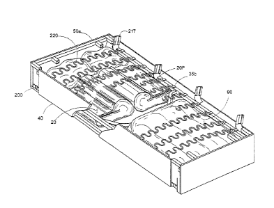
In one embodiment, as shown in Figs. 24 and 25, rigid central
support 35b is fixed and does not move. While there are
CA 2991517 2018-01-10
distinct advantages to the swivel gate 35 as described herein,
the present invention has a configuration in which the central
support is rigid central support 35b. The present invention
recognizes that the basic support frame 50a must have transverse
support extending generally perpendicular from the front to the
back of frame 50a. Each arm section 20 is constructed and
arranged such that in an unassembled configuration, they will
nest within a portion of the cavity defined by rigid central
support 35a.
In this embodiment, the overall purpose of having an unassembled
configuration in which components nest within the cavity is
still achieved without the need for the swivel swing gate.
Cushions 90 are similarly configured to nest within a portion of
the cavity defined by rigid central support 35a. Although
described as a "central support" it is not necessary that rigid
central support 35a be precisely centered and may be somewhat
off centered by +/- 20% of the length the long side of the frame
while still being substantially perpendicular to each of the
front and back longitudinal sides. In one embodiment, cushion
90a is configured to extend around the front of arm piece 20a.
In another embodiment, cushion 90b is flush along the legth of
arm piece 20b.
36
CA 2991517 2018-01-10
In one embodiment, the present invention includes each arm
section 20 configured to attach on top of support frame 50a.
In another embodiment, as is generally known, RTA furniture
typically is shipped without padding on features such as arms
and backs. The present invention, in one embodiment, has
provided not only RTA furniture, but also done so in a manner
such that padding and covering are shipped in a preassembled and
preconfigured arrangement. In one embodiment, arm 20A affixes
on to frame 40, and arm 20A has an extension portion 306A with a
bottom portion 302 and a corner portion 301 that assists for
affixation on to frame 40. In one embodiment, as shown in Fig.
35, spring portions 220 are constructed and arranged such that
they have sufficient movement in order to facilitate placement
of arm portions 20a within the cavity of frame 40. As shown in
Figs. 36 and 37 swivel swing gate 307 swivels by virtue of
connection into opening 308 of frame 50A. Swivel swing gate has
a generally perpendicular position when frame 58 is assembled as
a sofa and generally perpendicular orientation is moved to a
parallel orientation as shown in Fig. 39. This rotation of
either parallel to the general horizontal plane of frame 58 or
in the alternative rotation 180 degrees from its downward
perpendicular to an upward perpendicular orientation. This
37
CA 2991517 2018-01-10
upward perpendicular orientation further facilitates placement
of arm pieces 20A within frame 40.
As is generally understood, most RTA furniture products do not
come with articles such as upholstery and padding affixed
thereto. However, the present invention has developed a unique
configuration whereby RTA furniture, specifically RTA sofa and
RTA chairs, are shipped with padding and upholstery affixed
thereto. Affixation of upholstery is in any manner. A
preferred embodiment provides the upholstered arm and back
portions in which upholstery is affixed using hook and loop
fasteners as is known in the art. In general terms, the
upholstery has a general configuration corresponding to the
shape of an arm or back portion. One edge, preferably the lower
edge on which the arm or back portion attaches to the frame, has
hook and loop fasteners that both hold the upholstery in place,
and provide access to the male-female connectors used to fasten
the arm or back portion to the frame.
In an embodiment of the present invention, arm pieces are
affixed to the top of a frame without the need to have any
portion of an arm piece extend downward along side a frame. In
this configuration, an arm piece is still able to be securely
attached to a frame and provide ease of assembly of an RTA piece
38
CA 2991517 2018-01-10
of furniture. Additionally, RTA sofa and chairs of the present
invention are shipped with a back portion fully upholstered and
padded such that affixation of the back portion onto the frame
constitutes the complete assembly of the back portion of the RTA
furniture. In one embodiment a decorative panel on the front of
the arm piece extends downward along the height of the frame, as
best seen in Figs. 32 and 43.
As seen in Fig. 35, support springs 220 can be constructed to
move along the horizontal portion of frame 50a such that any
desired distance, such as distance represented by dimension "E"
and "F" in Fig. 35 can be varied as desired. A swivel swing
gate 307 in Fig. 35, is swiveled out of the storage cavity to
provide maximum storage volume form arm pieces 20a stored
within.
As is understood and shown in Figs. 35-37, swivel swing gate 307
is rotatable 360 degrees on a swivel through connection in
swivel cavity 308 in frame 50a. This allows swing gate 307 to
extend downward, perpendicular to the frame in an assembled
configuration and swing out of the storage cavity in an
unassembled configuration. Completely removing swing gates is
generally not desired as the swing gate provides strength and
stability and keeps the horizontal portions of the frame from
39
CA 2991517 2018-01-10
bowing inward towards each other.
In one embodiment, as shown in Figs. 41-45, more than one frame
is provided and the frames are connected when assembled to form
a larger article of furniture. Frame 601 has a support 606 and
connecting panel 605. There are also legs 608 along and
underneath panel 605. As shown in Fig 47, connection of 2 or
more frames at panel 605 and support 606 is through any
acceptable connection means. One such RTA connection utilizes
male-female connectors such as connecting screws 607.
In a disassembled configuration, as shown in Fig. 48, each frame
604 is stacked in opposition such that arm pieces 20a are
contained there between.
In another embodiment, the back portion can be split into 2 or
pieces. This can be in combination with a single frame
accommodation a two or three piece back portion or any other
configuration that facilitates the assembled and disassembled
storage, shipping, and assembly of the present invention. IN
one embodiment, as shown in Fig. 53, a frame with a length
denoted by dimension "F" is used as a single article of
furniture and can serve a dual purpose of a single article, or
assembled as an attached article to one or more additional
CA 2991517 2018-01-10
frames. In some embodiments, such as Fig. 53, even though a
particular frame 601 can be used as a single article without
attachment, it still may be required to have swing gate 307
incorporated therein in order to provide support such that
springs 220 do not urge horizontal portions of frame 50a towards
each other and distort the rectangular orientation of either 50a
601 or both.
Further, the present invention contemplates one taking a
complete assembled sofa, and separating the frames 601 of an
assembled sofa into two or more articles of furniture, for
example, separation into either a smaller sofa, single chair
portions, or combinations thereof.
While the invention has been described in its preferred form or
embodiment with some degree of particularity, it is understood
that this description has been given only by way of example and
that numerous changes in the details of construction,
fabrication, and use, including the combination and arrangement
of parts, may be made without departing from the spirit and
scope of the invention.
41
CA 2991517 2018-01-10