Note: Descriptions are shown in the official language in which they were submitted.
METHOD OF OPERATING A ROTARY ENGINE
TECHNICAL FIELD
The application relates generally to internal combustion engines and, more
particularly,
to fuel injection in such engines.
BACKGROUND OF THE ART
It is generally known to completely deactivate some cylinders of a
reciprocating internal
combustion engine to reduce fuel consumption at part load. Also, dynamic skip
fire
allows to rapidly stop and restart injection within a cylinder so that a
cylinder receives
no fuel, and does not undergo combustion, for example for a single combustion
event.
This is often accompanied with high speed modifications to the valve train to
reduce
pumping loss during the skipped injections. However, completely stopping
combustion
in a cylinder may create thermal loading on the engine and impede the ability
of the
engine for a rapid relight when higher power is required.
SUMMARY
In one aspect, there is provided a method of operating a rotary engine
including a rotor
engaged to a shaft and rotationally received in a housing to define a
plurality of working
chambers of variable volume, the method comprising: delivering a pilot
quantity of fuel
into a pilot cavity in successive communication with the working chambers;
igniting the
pilot quantity of fuel within the pilot cavity; and delivering a main quantity
of fuel into the
working chambers downstream of the successive communication of the pilot
cavity with
the working chambers; wherein at least one of the pilot quantity and the main
quantity is
varied between successive rotations of the shaft.
In another aspect, there is provided a method of operating a rotary engine
including first
and second rotor assemblies and a shaft, the first and second rotor assemblies
including a rotor engaged to the shaft and rotationally received in a housing
to define a
plurality of working chambers of variable volume, and a pilot cavity in
successive
1
CA 2991582 2018-01-10
communication with the working chambers, the method comprising: delivering a
pilot
quantity of fuel into the pilot cavity; igniting the pilot quantity of fuel
within the pilot
cavity; and delivering a main quantity of fuel into the working chambers
downstream of
the successive communication of the pilot cavity with the working chambers;
wherein at
least one of the pilot quantity and the main quantity of the first rotor
assembly is varied
between successive rotations of the shaft; wherein at least one of the pilot
quantity and
the main quantity is different between the first and second rotor assemblies
during at
least one of the successive rotations of the shaft.
DESCRIPTION OF THE DRAWINGS
Reference is now made to the accompanying figures in which:
Fig. 1 is a schematic partial cross-sectional view of a rotor assembly in
accordance with
a particular embodiment;
Fig. 2 is a schematic view of an engine in accordance with a particular
embodiment,
which can include rotor assemblies such as shown in Fig. 1;
Fig. 3 is a schematic cross-sectional view of a reciprocating piston assembly
in
accordance with a particular embodiment, which may be used in the engine of
Fig. 2;
and
Figs. 4-6 are schematic cross-sectional views of rotor assemblies in
accordance with
other particular embodiments, which may be used in the engine of Fig. 2.
DETAILED DESCRIPTION
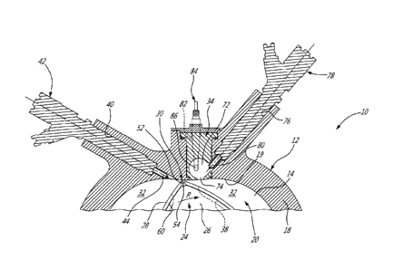
Referring to Fig. 1, a rotor assembly configured as a rotary intermittent
internal
combustion engine 10 is schematically and partially shown. The rotor assembly
10 is
known as a Wankel engine and comprises an outer body 12 having axially-spaced
end
walls 14 with a peripheral wall 18 extending therebetween to form an internal
cavity 20.
The inner surface 19 of the peripheral wall 18 of the internal cavity 20 has a
profile
defining two lobes, which is preferably an epitrochoid.
2
CA 2991582 2018-01-10
An inner body or rotor 24 is received within the internal cavity 20, with the
geometrical
axis of the rotor 24 being offset from and parallel to the axis of the outer
body 12. The
rotor 24 has axially spaced end faces 26 adjacent to the outer body end walls
14, and a
peripheral face 28 extending therebetween. The peripheral face 28 defines
three
circumferentially-spaced apex portions 30 (only one of which is shown), and a
generally
triangular profile with outwardly arched sides. The apex portions 30 are in
sealing
engagement with the inner surface of peripheral wall 18 to form three rotating
working
chambers 32 (only two of which are partially shown) between the inner rotor 24
and
outer body 12. A recess 38 is defined in the peripheral face 28 of the rotor
24 between
each pair of adjacent apex portions 30, to form part of the corresponding
chamber 32.
The working chambers 32 are sealed. Each rotor apex portion 30 has an apex
seal 52
extending from one end face 26 to the other and protruding radially from the
peripheral
face 28. Each apex seal 52 is biased radially outwardly against the peripheral
wall 18
through a respective spring. An end seal 54 engages each end of each apex seal
52,
and is biased against the respective end wall 14 through a suitable spring.
Each end
face 26 of the rotor 24 has at least one arc-shaped face seal 60 running from
each apex
portion 30 to each adjacent apex portion 30, adjacent to but inwardly of the
rotor
periphery throughout its length. A spring urges each face seal 60 axially
outwardly so
that the face seal 60 projects axially away from the adjacent rotor end face
26 into
sealing engagement with the adjacent end wall 14 of the internal cavity 20.
Each face
seal 60 is in sealing engagement with the end seal 54 adjacent each end
thereof.
Although not shown in Fig. 1, the rotor 24 is journaled on an eccentric
portion of a shaft
22 (Fig. 2) and includes a phasing gear co-axial with the rotor axis, which is
meshed
with a fixed stator phasing gear secured to the outer body co-axially with the
shaft. The
rotor 24 rotates the shaft 22 and the meshed gears guide the rotor 24 to
perform orbital
revolutions within the internal cavity 20. The shaft 22 performs three
rotations for each
orbital revolution of the rotor 24 in the internal cavity 20. Oil seals are
provided around
the phasing gear to prevent leakage flow of lubricating oil radially outwardly
thereof
between the respective rotor end face 26 and outer body end wall 14.
3
CA 2991582 2018-01-10
At least one inlet port (not shown) is defined through one of the end walls 14
or the
peripheral wall 18 for admitting air (atmospheric or compressed) into one of
the working
chambers 32, and at least one exhaust port (not shown) is defined through one
of the
end walls 14 or the peripheral wall 18 for discharge of the exhaust gases from
the
working chambers 32. The inlet and exhaust ports are positioned relative to
each other
and relative to the ignitor and fuel injectors (further described below) such
that during
each revolution of the rotor 24, each chamber 32 moves around the internal
cavity 20
with a variable volume to undergo the four phases of intake, compression,
expansion
and exhaust, these phases being similar to the strokes in a reciprocating-type
internal
combustion engine having a four-stroke cycle.
In a particular embodiment, these ports are arranged such that the rotor
assembly 10
operates under the principle of the Miller or Atkinson cycle, with its
volumetric
compression ratio lower than its volumetric expansion ratio. In another
embodiment, the
ports are arranged such that the volumetric compression and expansion ratios
are
equal or similar to one another.
A pilot cavity is defined in the outer body 12, for pilot fuel injection and
ignition. In the
embodiment shown example, the pilot cavity is in the form of a pilot
subchamber 72,
provided in an insert 34 received in a corresponding insert opening defined
through the
peripheral wall 18 of the outer body 12 and in communication with the internal
cavity 20,
for pilot fuel injection and ignition. In a particular embodiment, the insert
34 is made of a
material having a greater heat resistance than that of the peripheral wall 18,
which may
be made for example of aluminium. For example, the insert 34 may be made of an
appropriate type of ceramic or of an appropriate type of super alloy such as a
Nickel
based super alloy. Other configurations are also possible, including
configurations
where the pilot cavity (e.g. pilot subchamber 72) is defined directly in the
outer body 12,
for example in the peripheral wall 18.
The pilot subchamber 72 is in communication with the internal cavity 20. In
the
embodiment shown, the pilot subchamber 72 has a circular cross-section;
alternate
shapes are also possible. The pilot subchamber 72 communicates with the
internal
cavity 20 through at least one opening 74, and has a shape forming a reduced
cross-
4
CA 2991582 2018-01-10
section adjacent the opening 74, such that the opening 74 defines a
restriction to the
flow between the pilot subchamber 72 and the internal cavity 20. The opening
74 may
have various shapes and/or be defined by multiple holes.
The peripheral wall 18 has a pilot injector elongated hole 76 defined
therethrough in
proximity of the pilot subchamber 72, and in communication with the pilot
subchamber
72. A pilot fuel injector 78 is received and retained within the corresponding
hole 76,
with the tip 80 of the pilot injector 78 in communication with the pilot
subchamber 72.
The insert 34 and/or peripheral wall 18 have an ignitor elongated hole 82
defined
therein, also in communication with the pilot subchamber 72. An ignitor or
ignition
element 84 is received and retained within the corresponding hole, with the
tip of the
ignitor 84 communicating with the pilot subchamber 72, for example by having
the
ignitor 84 extending outside of the pilot subchamber 72 and the ignitor
elongated hole
communicating with the pilot subchamber 72 through an opening or passage 86
aligned
with the ignitor tip. In the embodiment shown, the ignitor 84 is a glow plug.
Alternate
types of ignitors 84 which may be used include, but are not limited to, plasma
ignition,
laser ignition, spark plug, microwave, etc.
It is understood that the pilot subchamber 72 may be omitted; in a particular
embodiment which is not shown, the pilot subchamber 72 is replaced by any
other
suitable type of pilot cavity formed in the outer body 12, for example a
recess defined in
the peripheral wall 18. The pilot fuel injector 78 and the ignitor 84 having
tips received in
or communicating with the pilot cavity so as to perform the fuel ignition
therein.
The peripheral wall 18 also has a main injector elongated hole 40 defined
therethrough,
in communication with the internal cavity 20 and spaced apart from the pilot
cavity and
pilot injector 78. A main fuel injector 42 is received and retained within
this
corresponding hole 40, with the tip 44 of the main injector 42 communicating
with the
internal cavity 20 at a point spaced apart from the communication between the
pilot
cavity and internal cavity 29 (e.g. from the subchamber opening 74). The main
injector
42 is located rearwardly of the subchamber opening 74 with respect to the
direction R
of the rotor rotation and revolution, i.e. downstream from the communication
74
5
CA 2991582 2018-01-10
between the pilot subchamber 72 and working chambers 32, and is angled to
direct fuel
forwardly into each of the rotating chambers 32 sequentially with a tip hole
configuration
designed for an adequate spray.
The pilot injector 78 and main injector 42 inject fuel, which in a particular
embodiment is
heavy fuel e.g. diesel, kerosene (jet fuel), equivalent biofuel, etc. into the
chambers 32.
Alternately, the fuel may be any other adequate type of fuel suitable for
injection as
described, including non-heavy fuel such as for example gasoline or liquid
hydrogen
fuel. In a particular embodiment, the pilot injector 78 and main injector 42
deliver the
same type of fuel, for example from a common fuel source; alternately, the
pilot injector
78 and main injector 42 may deliver different type of fuel. In a particular
embodiment,
up to 20% of a maximum fuel flow (sum of maximum flow of the pilot injector 78
and
main injector 42) is injected through the pilot injector 78 when used; other
values are
also possible, for example having the pilot injector 78 deliver up to 10%, or
up to 5%, of
the maximum fuel flow when used. The main injector 42 injects the fuel such
that each
working chamber 32 when in the combustion phase contains a lean mixture of air
and
fuel.
The pilot subchamber 72 may help create a stable and powerful ignition zone to
ignite
the overall lean working chamber 32 to create the stratified charge
combustion. The
pilot subchamber 72 may improve combustion stability, particularly but not
exclusively
for a rotor assembly which operates with heavy fuel below the self-ignition of
fuel. The
insert 34 made of a heat resistant material may advantageously create a hot
wall
around the pilot subchamber 78 which may further help with ignition stability.
In a particular embodiment, the rotor assembly 10 is operated in accordance
with the
following. A pilot quantity of fuel is delivered into the pilot subchamber 72
and ignited
within the pilot subchamber 72, and a main quantity of fuel is delivered into
the working
chambers 32 downstream of their communication with the pilot subchamber 72.
When
the rotor assembly 10 operates at maximum load, both the pilot quantity and
the main
quantity may correspond to a maximum pilot and main injection fuel flow,
respectively.
However, when the rotor assembly 10 operates at part load, some of the pilot
and/or
main injections are reduced or skipped, so as to reduce the fuel consumption,
noise
6
CA 2991582 2018-01-10
and/or vibrations on the rotor assembly 10. Accordingly, one or both of the
pilot and
main quantity is varied between successive rotations of the shaft 22, i.e.
between
successive working chambers 32 (since the shaft 22 performs three rotations
for each
complete revolution of the rotor 24, each shaft rotation corresponds to fuel
injection in
one of the working chambers 32). For example, the pilot and/or main injection
quantity
may be zero (skipped injection) for at least one of the successive rotations
of the shaft
22, and greater than zero (e.g., maximum value) for at least another one of
the
successive rotations of the shaft 22.
Various injection patterns may be used to vary the quantity of fuel injected
by the pilot
and/or main injector(s) 78, 42 between the successive rotations of the shaft
22. In a
particular embodiment, the injection pattern is repeated for each set of
first, second and
third successive rotations of the shaft 22, and accordingly each of the three
working
chambers 32 has its particular injection conditions. For example, for the
first shaft
rotation (first working chamber 32), the main quantity is zero and the pilot
quantity is
greater than zero, i.e. the main injection is skipped while a pilot injection
is performed;
for the second rotation (second working chamber 32), the main and pilot
quantities are
both zero, i.e. both the main and pilot injections are skipped; and for the
third rotation
(third working chamber 32), the main and pilot quantities are both greater
than zero, i.e.
a pilot and main injections are both performed.
Various other injection patterns can be used. The following are a few non-
limiting
examples, where x is a natural number greater than 1:
- the pilot injection is skipped (pilot quantity of zero) for one of x
successive
rotations of the shaft 22, and performed (pilot quantity greater than zero)
for the
remaining x-1 successive rotations of the shaft 22. For example, the pilot
injection is skipped every second shaft rotation, or every third shaft
rotation, or
every fourth shaft rotation, etc.;
-
the pilot injection is performed (pilot quantity greater than zero) for one of
x
successive rotations of the shaft 22, and skipped (pilot quantity of zero) for
the
remaining x-1 successive rotations of the shaft 22. For example, the pilot
7
CA 2991582 2018-01-10
injection is performed only every second shaft rotation, or only every third
shaft
rotation, or only every fourth shaft rotation, etc.
- the main injection is skipped (main quantity of zero) for one of x
successive
rotations of the shaft 22, and performed (main quantity greater than zero) for
the
remaining x-1 successive rotations of the shaft 22. For example, the main
injection is skipped every second shaft rotation, or every third shaft
rotation, or
every fourth shaft rotation, etc.;
- the main injection is performed (main quantity greater than zero)
for one of x
successive rotations of the shaft 22, and skipped (main quantity of zero) for
the
remaining x-1 successive rotations of the shaft 22. For example, the main
injection is performed only every second shaft rotation, or only every third
shaft
rotation, or only every fourth shaft rotation, etc.;
- the main injection includes two sequential injection pulses for each working
chamber 32 (e.g. main pulse and post injection pulses), and one of these
pulses
is omitted (skipped) for one of the x successive rotations of the shaft 22,
and
performed for the remaining x-1 successive rotations of the shaft 22. For
example, one of the pulses is skipped every second shaft rotation, or every
third
shaft rotation, or every fourth shaft rotation, etc. The other pulse can
remain
constant, have a variable quantity, or be skipped using a similar or different
pattern;
- with the main injection includes two sequential injection pulses,
and one of the
pulses is performed for one of x successive rotations of the shaft 22, and
omitted (skipped) for the remaining x-1 successive rotations of the shaft 22.
For
example, one of the pulses is performed only every second shaft rotation, or
only every third shaft rotation, or only every fourth shaft rotation, etc. The
other
pulse can remain constant, have a variable quantity, or be skipped using a
similar or different injection pattern.
8
CA 2991582 2018-01-10
It is understood that the examples of injection patterns for the pilot
injection by the pilot
injector 78 can be combined with a main injection by the main injector 42
which is
maintained throughout the x successive shaft rotations, whether with a fixed
or variable
main quantity, or skipped following any suitable injection pattern, and that
the examples
of injection patterns for the main injection by the main injector 42 can be
combined with
a pilot injection by the pilot injector 78 which is maintained throughout the
x successive
shaft rotations, whether with a fixed or variable pilot quantity, or skipped
following any
suitable injection pattern. The pilot injection can also be performed in two
or more
pulses, and the main injection can be performed in more than two pulses; each
pulse
can be varied, for example as indicated above, without or with variation of
the other
pulses.
In a particular embodiment, an engine control unit 16 (see Fig. 2), for
example forming
part of a full authority digital engine (or electronics) control (FADEC),
controls the pilot
and main fuel injectors 78, 42, for example through actuation of electronic
valves within
the fuel injectors 78, 42 to control the injection pulses. The flexibility of
the engine
control software allows for the choice of firing or skipping all injection
opportunities. For
example, a control algorithm may be created to control the injection and apply
injection
pattern(s) based on the power demand on the rotor assembly 10, so as to
implement an
injection pattern (e.g. including pilot and/or main injection skipping) when
the power
demand is lower than a threshold value, or select between multiple injection
patterns
each corresponding to a respective range in power demand.
In a particular embodiment, the ability to keep one of the pilot and main
injectors 78, 42
on while skipping the other of the pilot and main injectors 78, 42 allows for
the rotor
assembly 10 to always stay warm and reduce thermal loading, and facilitates
engine
relight when needed.
In a particular embodiment, an engine includes a single rotor assembly 10,
i.e. the rotor
assembly 10 can be referred to as a rotary intermittent internal combustion
engine. In
another embodiment, multiple rotor assemblies 10 are used together to defined
an
intermittent internal combustion engine. Referring to Fig. 2, an intermittent
internal
combustion engine 8 is schematically shown, including four (4) rotor
assemblies 10
9
CA 2991582 2018-01-10
engaged to the same shaft 22. It is understood that the engine 8 can includes
any other
suitable number of rotor assemblies 10, i.e. one (1) rotor assembly 10, two
(2) or three
(3) rotor assemblies, or more than four (4) rotor assemblies 10.
The pilot and/or main quantities of fuel can be varied as set forth above, for
a single
one, only some, or all of the rotor assemblies 10 forming part of the engine
8. In a
particular embodiment, the variation in pilot and main injection is the same
for all of the
rotor assemblies 10; in another embodiment, at least one of the rotor
assemblies 10
has a constant pilot and main injection throughout the rotations of the shaft
22, and at
least another one of the rotor assemblies 10 has a variable pilot and/or main
injection
between successive rotations of the shaft 22, as set forth above. Accordingly,
one or
both of the pilot and main quantities of fuel is different between two of the
rotor
assemblies 10 during at least one of the successive rotations of the shaft 22.
One or
both of the pilot and main quantities of fuel may be different between more
than two, for
example all, of the rotor assemblies 10 during at least one of the successive
rotations of
the shaft 22. For example, in a particular embodiment one or both of the pilot
quantity
and the main quantity is different between first, second and third rotor
assemblies 10 of
the engine 8 during the at least one of the successive rotations of the shaft
22.
Since the rotor assemblies 10 do not include valves at the inlet and outlet
ports, and the
inlet is not throttled, the injection skipping can be performed without the
need for valve
train modifications.
In a particular embodiment, implementation of injection patterns (e.g. with
pilot and/or
main injection skipping) on more than one, for example all, of the rotor
assemblies 10 of
the engine 8 allows to distribute the load reduction throughout the engine 8.
In a particular embodiment, implementation of injection patterns (e.g. with
pilot and/or
main injection skipping) allows for a reduction in fuel consumption, noise,
vibrations
and/or torque pulsing during operation at part load, while decreasing wear on
the
engine components, as compared with operation of an engine where injection in
one or
more of the rotor assemblies 10 is completely shut off during part load
operation.
CA 2991582 2018-01-10
In a particular embodiment, the engine 8 including one or more rotor
assemblies 10 is
used in a compound cycle engine system or compound cycle engine such as
described
in Lents et al.'s US patent No. 7,753,036 issued July 13, 2010 or as described
in Julien
et al.'s US patent No. 7,775,044 issued August 17, 2010, or as described in
Thomassin
et al.'s U.S. patent publication No. 2015/0275749 published October 1, 2015,
or as
described in Bolduc et al.'s U.S. patent publication No. 2015/0275756
published
October 1, 2015, the entire contents of all of which are incorporated by
reference
herein. The compound cycle engine may be used as a prime mover engine, such as
on
an aircraft or other vehicle, or in any other suitable application. In any
event, in such a
system, air is compressed by a compressor before entering the rotor assembly,
and the
engine drives one or more turbine(s) of the compound engine. In another
embodiment,
the engine 8 is used without a turbocharger, with air at atmospheric pressure.
When the engine 8 is used with a turbine, for example in a compound cycle
engine as
mentioned above, a post-injection pulse of the main injector 42 can be
maintained while
the main injection pulse of the main injector 42 and/or pilot injection of the
pilot injector
78 are skipped; maintaining the post-injection pulse may help maintain
adequate inlet
conditions for the turbine receiving the engine exhaust.
In a particular embodiment, implementation of injection patterns (e.g. with
pilot and/or
main injection skipping) allows to reduce the power provided by the engine 8
without
the need to resort to a reduction in the air compression upstream of the
engine 8 (for
example, through control of variable inlet guide vanes of the compressor in
the
compound cycle engine), and/or a change in the air temperature upstream of the
engine 8 (for example, by bypassing an intercooler).
For example, in a particular embodiment of compound cycle engine used as a
turboprop, the compressor is designed to be efficient in flight (e.g.
compression ratio of
6:1 or 7:1), but may need to have a significantly smaller compression ratio
when the
compound cycle engine is used at idle on the ground (for example, 3:1), which
may be
difficult to obtain with variable inlet guide vanes. Implementation of
injection patterns
(e.g. with pilot and/or main injection skipping) allows for a reduction of
power without
reducing the compression ratio of the compressor, which may allow the
compressor to
11
CA 2991582 2018-01-10
function at a higher compression ratio when at idle on the ground (for
example, 4:1).
Accordingly, implementation of injection patterns (e.g. with pilot and/or main
injection
skipping) may allow for an easier match between the requirements of the
components
of the compound cycle engine.
In another embodiment and still referring to Fig. 2, the engine 8 is a
reciprocating
intermittent internal combustion engine including at least two (four in the
embodiment
shown) cylinders 10' each receiving a reciprocating piston. As illustrated in
Fig. 3, each
piston 24' is received in a corresponding internal cavity 20' of the cylinder
housing 12' to
define a working chamber 32 of variable volume and undergoing the four stroke
phases
of intake, compression, expansion and exhaust, with the reciprocating pistons
24'
engaged to the engine shaft 22 (Fig. 2). The engine 8 includes, for each
cylinder 10', a
main injector 42, an ignitor 84, a pilot subchamber 72 (or other suitable
pilot cavity)
communicating with the working chamber 32 separately from the main injector
42, and
a pilot injector 78 in communication with the pilot subchamber 72.
The pilot and/or main quantities of fuel can be varied as set forth above, for
a single
one, only some, or the entirety of the cylinders 10' forming part of the
engine 8, as
described above, for example using one of the injection patterns described for
the rotor
assemblies 10, or any other suitable injection pattern. In a particular
embodiment,
implementation of injection patterns (e.g. with pilot and/or main injection
skipping) on
more than one, for example all, of the cylinders 10' of the engine 8 allows to
distribute
the load reduction throughout the engine 8.
In another embodiment, the engine 8 includes one or more rotor assemblies
configured
as a non-Wankel engine. A "non-Wankel" engine, as used herein, means a rotary
engine suitable for use with the present invention, but excluding Wankel type
engines.
In a particular embodiment, the rotor assembly may be a single or eccentric
type rotary
engine in which the rotor rotates about a fixed center of rotation. For
example, the rotor
assembly may be a sliding vane engine, such as described in US patent No.
5,524,587
issued June 11, 1996 or in US patent No. 5,522,356 issued June 4, 1996, the
entire
contents of both of which are incorporated by reference herein.
12
CA 2991582 2018-01-10
Referring to Fig. 4, an example of a rotor assembly 100 configured as a
sliding vane
engine is shown. The rotor assembly 100 includes an outer body 112 defining an
internal cavity 20 receiving a rotor 124 having a number of vanes 125. The
rotor 124
includes an inner hub assembly 127 rotating about a first axis and an outer
hub
assembly 129 rotating about a second axis offset from the first axis, with the
two hub
assemblies 127, 129 being mechanically linked. The vanes 125 are pivotally
connected
to the inner hub assembly 127 and are slidingly engaged through slots defined
between
adjacent sections of the outer hub assembly 129. The sections of the outer hub
assembly 129 are thus sealingly engaged to the vanes 125 at different
distances from
the first axis of the inner hub assembly 127, defining a plurality of chambers
32 of
variable volume within the internal cavity 20 around the rotor 124.
In the embodiment shown, the pilot subchamber 72 of the rotor assembly 100 is
defined
in the insert 34 (for example made of a material having a greater heat
resistance than
that of the peripheral wall 118) received in an insert opening of a peripheral
wall 118 of
the outer body 112; alternately the pilot subchamber 72 may be defined
directly in the
outer body 112, for example in the peripheral wall 118, or the pilot injector
72 may be
received in any other suitable type of pilot cavity formed in the outer body
112. The
peripheral wall 118 also has a main injector elongated hole 40 defined
therethrough, in
communication with the internal cavity 20 and spaced apart from the insert 34.
The
peripheral wall 118 and/or the insert 34 has the pilot injector elongated hole
76 and the
ignitor elongated hole 82 defined therethrough in communication with the pilot
subchamber 72.
In another particular embodiment, the rotor assembly may be an oscillatory
rotating
engine, including two or more rotors rotating at different angular velocities,
causing the
distance between portions of the rotors to vary and as such the chamber volume
to
change. Referring to Fig. 5, an example of such a rotor assembly is shown. The
rotor
assembly 200 includes an inner rotor 224 and an outer body or rotor 212
rotating at
different angular velocities, the outer rotor 212 defining an internal cavity
20 in which
the inner rotor 212 is received. Chambers 32 of variable volume are defined
within the
internal cavity 20 around the inner rotor 224.
13
CA 2991582 2018-01-10
In the embodiment shown, the pilot subchamber 72 of the rotor assembly 200 is
defined
in the insert 34 (for example made of a material having a greater heat
resistance than
that of the peripheral wall 218) received in an insert opening of a peripheral
wall 218 of
the outer body 212; alternately the pilot subchamber 72 may be defined
directly in the
outer body 212, for example in the peripheral wall 218, or the pilot injector
72 may be
received in any other suitable type of pilot cavity formed in the outer body
212. The
peripheral wall 218 also has the main injector elongated hole 40 defined
therethrough
spaced apart from the insert 34, and the peripheral wall 218 and/or the insert
34 has the
pilot injector elongated hole 76 and the ignitor elongated hole 82 defined
therethrough.
In another particular embodiment, the rotor assembly is configured as a
planetary
rotating engine having a different geometry than that of the Wankel engine.
Referring to
Fig. 6, an example of such a rotor assembly is shown. The rotor assembly 300
includes
an outer body 312 forming an internal cavity 20 with a peripheral inner
surface thereof
having an epitrochoid profile defining three lobes. The rotor assembly 300
also includes
a rotor 324 with four apex portions 330 in sealing engagement with the
peripheral inner
surface to form four rotating working chambers 32 of variable volume within
the internal
cavity 20 around the rotor 324. The rotor 324 is journaled on an eccentric
portion of a
shaft and performs orbital revolutions within the internal cavity 20.
In the embodiment shown, the pilot subchamber 72 of the rotor assembly 300 is
defined
in the insert 34 (for example made of a material having a greater heat
resistance than
that of the peripheral wall 218) received in an insert opening of a peripheral
wall 318 of
the outer body 312; alternately the pilot subchamber 72 may be defined
directly in the
outer body 312, for example in the peripheral wall 318, or the pilot injector
72 may be
received in any other suitable type of pilot cavity formed in the outer body
312. The
peripheral wall 318 also has the main injector elongated hole 40 defined
therethrough
spaced apart from the insert 34, and the peripheral wall 318 and/or the insert
34 has the
pilot injector elongated hole 76 and the ignitor elongated hole 82 defined
therethrough.
The above description is meant to be exemplary only, and one skilled in the
art will
recognize that changes may be made to the embodiments described without
departing
from the scope of the invention(s) disclosed. For example, the mechanical
14
CA 2991582 2018-01-10
arrangements of the rotor assemblies described above are merely examples of
many
possible configurations which are suitable for use with the present
invention(s). Any
suitable injector configuration and arrangement may be used. Hence,
modifications
which fall within the scope of the present invention will be apparent to those
skilled in
the art, in light of a review of this disclosure, and such modifications are
intended to fall
within the appended claims.
CA 2991582 2018-01-10