Note: Descriptions are shown in the official language in which they were submitted.
MULTIFOCAL METHOD AND APPARATUS FOR STABILIZATION OF
OPTICAL SYSTEMS
Cross-Reference to Related Application
[0001] [[this paragraph intentionally left blank]]
Field
[0002] This disclosure relates to microscopy. Various embodiments measure and
compensate for sample drift. The invention has particular application to high-
resolution
and super-resolution microscopy.
Background
[0003] Super-resolution microscopy techniques permit exceedingly high
resolution
imaging of specimens using optical radiation. The resolution can be finer than
the
wavelength of the optical radiation used for imaging. Such techniques include
including
stimulated emission depletion (STED) and RESOLFT microscopy (see e.g. Hell SW.
Nat.
Biotech. 2003; 21:1347; and Hell SW. Science. 2007; 316:1153.), saturated
structured
illumination microscopy (SSIM) (see e.g. Gustafsson MGL. Proc. Natl. Acad.
Sci., USA.
2005;102:13081), stochastic optical reconstruction microscopy (STORM) (see
e.g. Rust
MJ, Bates M, Zhuang X. Nat. Meth. 2006;3:793; Bates M, Huang B, Dempsey GT,
Zimang X. Science. 2007;317:1749; and Huang, Bo "Three-dimensional Super-
resolution
Imaging by Stochastic Optical Reconstruction Microscopy" Science 319 (5864):
810-813
(2008)), photoactivated localization microscopy (PALM) (see e.g. Betzig E, et
al. Science.
2006;313:1642; and Hess ST, Girirajan TPK, Mason MD. Biophys. J. 2006;91:4258)
and
other methods using similar principles (see e.g. Sharonov A, Hochstrasser RM.
Proc. Natl.
Acad. Sci., USA. 2006;103:18911; Egner A, et al. Biophys. J. 2007;93:3285; and
Bock H,
et al. Appl. Phys. B. 2007;88:161). Such techniques can achieve lateral
resolutions of
1
Date Regue/Date Received 2022-08-08
CA 02991920 2018-01-10
WO 2016/168941
PCT/CA2016/050474
better than 50 nm. Many of these techniques are single-molecule-localization
(SML)
techniques which create conditions in which light is emitted from single
molecules. The
knowledge that light emissions occur at discrete locations can be used to
create
exceptionally high resolution images.
[0004] STORM uses photo-switchable fluorescent probes to temporally separate
the
otherwise spatially overlapping images of individual molecules, allowing for
precise
localization of individual fluorescent labels in the sample. Although three
dimensional
(3D) STORM based on astigmatic single-molecule localizations has been gaining
popularity, high accuracy deep imaging still faces many challenges. In STORM
microscopy, an acquisition time of several minutes is often needed to
accumulate a
sufficient number of fluorophore positions and construct an informative image.
[0005] Sample drift is movement of a sample being imaged relative to imaging
apparatus
(e.g. relative to an objective lens and imaging sensor such as a camera).
Sample drift
compromises the precision and accuracy of imaging. Sample drift can occur in
all three
dimensions, and arises from a wide number of sources including mechanical
vibrations
and other mechanical movements, temperature changes, temperature gradients and
the
like.
[0006] Although the lateral accuracy of fluorophore localization bysuper-
resolution
imaging techniques such as STORM can be better than 10 nm, sample drift due to
thermal
gradients or mechanical motions can easily be in the hundreds of nanometers.
In
conventional fluorescence microscopy typical resolutions are on the order of
300 nm or
more and sample drifts of 100 nm n may be tolerable. In super-resolution
microscopy a
sample drift of 100 nm or more during acquisition may destroy the high
resolution nature
of the image. Therefore minimizing sample drift often becomes the most
important factor
in determining the performance of a super-resolution microscope.
[0007] Furthermore, the above techniques can require relatively long data
acquisition
times (e.g. times on the order of several minutes or more are not uncommon).
Such long
data acquisition place even higher demands on minimizing sample drift. SML
methods
may routinely take minutes to hours to obtain a single image. In SML-based
super-
resolution methods, minimizing sample drift over long periods of time is
desirable.
2
CA 02991920 2018-01-10
WO 2016/168941
PCT/CA2016/050474
[0008] Various approaches to correcting for positional drift have been
described in the
literature. These include online correction using fiducial markers (see e.g.
Pertsinidis, A.,
Zhang, Y. & Chu, S. Nature 466, 647-651 (2010) and Carter, A.R. et al. Appl.
Opt. 46,
421-427 (2007)) as well as offline processing algorithms using a bright-field
image (see
e.g. Mennella, V. et al. Nat. Cell Biol. 14, 1159-1168 (2012)) or consecutive
blink
tracking (see e.g. Geisler, C. et al. Opt. Express 20 (2012)). Other
references describing
image stabilization or drift correction techniques include:
= Ashley R. Carter et al: "Stabilization of an optical microscope to 0.1 nm
in three
dimensions", APPLIED OPTICS, vol. 46, no. 3, 1 January 2007 (2007-01-01),
page 421
= W02013063096A1 Multifunction autofocus system and method for automated
microscopy;
= US20130070339 Method and device for image stabilization in an optical
observation or measurement instrument;
= US20050141081 Method for correcting drift in an optical device; and
= US7928409 Real-time, active picometer-scale alignment, stabilization, and
registration in one or more dimensions.
[0009] Offline processing algorithms have difficulty in correcting for large
drifts. Real-
time drift correction techniques using fiducial markers have so-far produced
the best
super-resolution images. Fiducial markers, typically fluorescent beads affixed
to a
coverslip, are used as reference points to measure and correct for drift. The
positions of
bright fiducial markers can typically be determined within an error of a few
nm. However,
when the objective lens is focused at a depth into the sample greater than the
depth of field
provided by the objective lens (typically on the order of 0.51..tm or less),
the fiducial
markers on the coverslip are out of focus making it difficult or impossible to
obtain
accurate measurements of drift.
[0010] There is a need for practical and cost-effective ways to compensate for
sample drift
in super-resolution microscopy.
Summary
[0011] The invention has a number of aspects. These include, without
limitation:
= methods for super-resolution imaging which compensate for sample drift;
3
CA 02991920 2018-01-10
WO 2016/168941
PCT/CA2016/050474
= apparatus for compensating for sample drift in microscopy ¨ such
apparatus may
be integrated into a microscope or may be provided as an add-on or retrofit
system
to an existing microscope.
[0012] Methods according to some embodiments acquire light from a sample using
one
focal plane (a sample focal plane) and acquire light from one or more fiducial
markers
using a different focal plane (a fiducial marker focal plane). The same
objective lens may
be used to acquire both the light from the sample and the light from the
fiducial markers.
For example, the fiducial marker focal plane may coincide with fiducial
markers such as
microbeads, nanoparticles, or quantum dots attached to a coverslip to yield
images of the
fiducial markers that permit precise determination of changes in position of
the fiducial
markers.
[0013] The sample focal plane may be deep within the sample (e.g. deeper than
a depth of
field of the objective lens). In some embodiments, the sample focal plane is
more than
1 pm or more than 5 pm deeper than the fiducial marker focal plane. In some
embodiments, the sample focal plane is spaced deeper than the fiducial marker
focal plane
by at least 2, 3, or 5 times a depth of field of the imaging system used to
image target
features in the image focal plane.
[0014] Real-time nanometer-scale drift correction may be performed based on
the
observed changes in position of the fiducial markers. This may provide
essentially drift-
free images that more faithfully represent a labeled structure of a sample
being imaged
than images for which drift correction is not performed.
[0015] Fiducial markers and a region of interest in a sample may be imaged
using separate
focal planes in various ways. These include:
= Providing separate imaging systems which include separate imaging light
detectors
(e.g. cameras) for collecting light from the sample and the fiducial markers.
One or
both of the imaging systems include one or more variable focusing elements
such
that each of the sample focal plane and the fiducial marker focal plane may be
set
to a corresponding desired depth. The optical paths of both imaging systems
pass
through the same objective lens. Other parts of the optical paths of the
imaging
systems may also overlap.
4
CA 02991920 2018-01-10
WO 2016/168941
PCT/CA2016/050474
= Providing an optical system that focuses light from the sample to a first
area of an
imaging light detector and another optical system that focuses light from the
fiducial markers onto a second area of the imaging light detector.
= Providing one variable-focus imaging system and a controller configured
to focus
the imaging system on the sample focal plane to obtain light from the sample
and
periodically re-focus the imaging system on the fiducial marker focal plane to
image the fiducial markers. The images of the fiducial markers may be obtained
with relatively brief exposures obtained frequently enough to provide near
real-
time drift correction. This option has the advantage of reduced cost but may
provide poorer performance than the options mentioned above which can provide
continuous correction for sample drift.
[0016] In embodiments which provide separate optical paths for directing light
from the
sample and light from the fiducial markers, light from the sample and light
from the
fiducial markers may be separated using suitable filters. In some embodiments
light from
the sample and light from the fiducial markers have different wavelengths and
wavelength-selective filters such as dichroic mirrors may be used to separate
light from
these two sources. Focusing elements may be provided in parts of one or both
optical
paths that are not common to facilitate establishment of the sample focal
plane and the
fiducial marker focal plane at different depths relative to the objective
lens.
[0017] The nature of light to be collected from the sample will depend on the
type of
super-resolution imaging being performed and on the nature of the sample. In
some
embodiments the light from the sample comprises fluorescence emitted from
molecules
within the sample. Such fluorescence may be generated by applying incident
optical
radiation to the sample at one or more wavelengths that are different from the
wavelength(s) of the light to be collected from the sample for imaging
purposes.
[0018] The light to be collected from the fiducial markers may arise from
reflection from
the fiducial markers, fluorescence within the fiducial markers or some other
mechanism.
The light to be collected from the fiducial markers may result when the
fiducial markers
are exposed to incident optical radiation. The incident optical radiation may,
but does not
necessarily play a role in causing emission of the light to be collected from
the sample.
The incident optical radiation that results in the light to be collected from
the fiducial
CA 02991920 2018-01-10
WO 2016/168941
PCT/CA2016/050474
markers may have the same or different wavelength(s) as the light to be
collected from the
fiducial markers. Various possibilities exist for illuminating the sample and
fiducial
markers. These include, without limitation:
= Illuminating the sample and fiducial markers with light of a first
wavelength;
allowing the light of the first wavelength to cause the sample to emit light
of a
second wavelength (either on its own or in combination with additional
incident
light having other properties); allowing the light of the first wavelength to
reflect
from the fiducial markers; collecting light of the second wavelength from the
sample focal plane and collecting light of the first wavelength from the
fiducial
marker focal plane;
= Illuminating the sample and fiducial markers with light of a first
wavelength;
allowing the light of the first wavelength to cause the sample to emit light
of a
second wavelength (either on its own or in combination with additional
incident
light having other properties); allowing the light of the first wavelength to
cause
the fiducial markers to emit light of a third wavelength (e.g. by
fluorescence);
collecting light of the second wavelength from the sample focal plane and
collecting light of the third wavelength from the fiducial marker focal plane;
= Illuminating the sample and fiducial markers with light of a first
wavelength and
light of a fourth wavelength; allowing the light of the first wavelength to
cause the
sample to emit light of a second wavelength (either on its own or in
combination
with additional incident light having other properties); allowing the light of
the
fourth wavelength to reflect from the fiducial markers; collecting light of
the
second wavelength from the sample focal plane and collecting light of the
fourth
wavelength from the fiducial marker focal plane; and
= Illuminating the sample and fiducial markers with light of a first
wavelength and
light of a fourth wavelength; allowing the light of the first wavelength to
cause the
sample to emit light of a second wavelength (either on its own or in
combination
with additional incident light having other properties); allowing the light of
the
fourth wavelength to cause the fiducial markers to emit light of a third
wavelength
(e.g. by fluorescence); collecting light of the second wavelength from the
sample
focal plane and collecting light of the third wavelength from the fiducial
marker
focal plane.
6
CA 02991920 2018-01-10
WO 2016/168941
PCT/CA2016/050474
[0019] One aspect of the invention provides a method for imaging a sample,
comprising:
(a) providing one or more fiducial markers near the sample; (b) imaging the
sample using
a first imaging system comprising an objective lens; (c) and while imaging the
sample: (d)
imaging the one or more fiducial markers with a second imaging system by way
of the
objective lens; (e) processing images of the one or more fiducial markers
obtained by the
second imaging system to yield a measure of drift of the fiducial markers
relative to the
objective lens; and (0 controlling an actuator to correct for the drift.
[0020] In some embodiments, the method additionally comprises illuminating the
sample
and fiducial markers using light emitted from one or more lasers.
[0021] The actuator may comprise a piezoelectric actuator operative to
independently
control the position of the sample relative to the objective lens in two
dimensions
orthogonal to an optical axis of the objective lens.
[0022] In some embodiments, the first and second imaging systems are sensitive
to
different light wavelength characteristics.
[0023] The method may additionally comprise imaging the sample in a different
focal
plane than the focal plane of the fiducial markers, and independently focusing
the first and
second imaging systems.
[0024] The method may automatically focus on and image the fiducial markers.
[0025] In some embodiments, an asymmetrical optical element is provided in the
imaging
path of the second imaging system, and processing images of the one or more
fiducial
markers may comprise determining a distortion in the images of the fiducial
markers due
to astigmatism and determining a component of the drift in a direction along a
z-axis
parallel to an optical axis of the objective lens based on the distortion. The
asymmetrical
optical element may comprise, for example, a cylindrical lens, or a pair of
concave and
convex cylindrical lenses. Determining the distortion may comprise determining
an aspect
ratio of height to width in images of the fiducial markers, and operating the
actuator in
response to the determined aspect ratio.
[0026] In some embodiments, a plurality of fiducial markers is provided, and
imaging the
fiducial markers may involve averaging the drifts of each of the plurality of
markers.
Averaging the drifts may comprise eliminating one or more outliers.
7
CA 02991920 2018-01-10
WO 2016/168941
PCT/CA2016/050474
[0027] The method may additionally comprise obtaining multiple images of the
sample.
[0028] In some embodiments, detecting light from the sample comprises
detecting light
emitted by fluorophores within the sample.
[0029] In some embodiments, the first and second light sensors are provided by
different
areas of a single imaging sensor. The Imaging sensor may be a CCD array.
[0030] Some embodiments image the sample using one of a variety of microscopy
imaging techniques, including but not limited to: STED, RESOLFT, SSIM, STORM,
SIM
and PALM techniques.
[0031] In some embodiments, an electrically tunable lens (ETL) is used in an
optical path
of the second image sensor to enable the first image sensor and the second
image sensor to
independently focus at different focal planes. Using an ETL may extend the
depth of field
of the objective lens, and allows for decoupling focal planes of the first and
second image
sensors.
[0032] Some embodiments comprise gradually or stepwise increasing one or more
of: an
exposure time; a gain of the second imaging system; and an intensity of the
light source
that illuminates the fiducial markers over the course of .acquiring a super-
resolution
image. This may be done to compensate for photo-bleaching of the fiducial
markers for
example.
[0033] In some embodiments, the first and second imaging systems comprise a
single
CCD, and imaging the sample comprises alternating the focus of the imaging
system
between the fiducial markers and the sample.
[0034] In certain embodiments, the invention provides a method of stabilizing
an image
generated by an optical microscope. The method comprises: (a) applying one or
more light
sources to a sample and a fiducial element held on a nanopositioning stage,
the sample
comprising a target element affected by a positional drift; (b) detecting
photons emitted
from the fiducial element and the target element, wherein the photons emitted
by the
fiducial element and the target element are detected by independent image
sensors; (c)
using an asymmetrical optical element such as a cylindrical lens to introduce
an astigmatic
effect to locate the three-dimensional (3D) position of the fiducial markers;
and (d)
correcting the 3D positional drift of the sample using an algorithm configured
to calculate
8
CA 02991920 2018-01-10
WO 2016/168941
PCT/CA2016/050474
the location of the fiducial element and applying closed-loop feedback control
by way of a
nanopositioning stage, thereby stabilizing the sample.
[0035] In one aspect of the invention the target element and the fiducial
element are
separated in space along the path of the optical axis/z-direction.
[0036] In another aspect of the invention the image is a two dimensional (2D)
or 3D
image and is stabilized in all three dimensions to produce a drift free image.
[0037] In another aspect of the invention the nanopositioning stage is a three-
axis
nanopositioning stage used for positional feedback.
[0038] The sample being imaged may be substantially 2D or 3D. The sample may
comprise a biological cell. The sample may incorporate the fiducial
element(s).
[0039] In some embodiments, the fiducial element is affixed to or is part of
the sample.
[0040] In another aspect of the invention the sample drift is corrected to
less than about
50nm in at least one direction. In yet a further aspect of the invention the
sample drift is
corrected to less than about lOnm in one, two, or three axes. In yet a further
aspect of the
invention the sample drift is corrected to less than about 3nm in one, two, or
three axes. In
yet a further aspect of the invention the sample drift is corrected to less
than about lnm in
at least one direction.
[0041] In some embodiments of the invention the sample drift is corrected to
less than
about 2nm in the X and/or Y direction and less than 5nm in the Z direction. In
some
embodiments of the invention sample drift is corrected to less than about lnm
in the X
and/or Y direction and less than 2.5nm in the Z direction. Some embodiments
stabilize
sample drift for periods of at least several minutes. For example, some
embodiments
stabilize sample drift for about one hour or longer.
[0042] In yet a further aspect of the invention, a method of stabilizing an
image generated
by an optical microscope is provided comprising: (a) applying a light source
to a sample
and a fiducial element held on a nanopositioning stage, the sample comprising
a target
element and having a positional drift; (b) detecting photons emitted from the
fiducial
element with a first image sensor; (c) detecting photons emitted from the
target element
with a second image sensor; and (c) correcting the positional drift of the
sample using an
9
CA 02991920 2018-01-10
WO 2016/168941
PCT/CA2016/050474
algorithm configured to calculate the location of the fiducial element and
having closed-
loop feedback control of the nanopositioning stage, thereby stabilizing the
image.
[0043] In one aspect of this invention a relay lens is used in the optical
path of the first
image sensor to enable the first image sensor and the second image sensor to
independently focus at different focal planes. Using this method the image of
the target
element on the second image sensor is brought into focus and a relay lens may
be used to
bring the image of the fiducial element into focus on the first image sensor.
Alternately,
the image of the fiducial element may be brought into focus on the first image
sensor and a
relay lens may be used to bring the image of the target element into focus on
the second
image sensor.
[0044] A further aspect of the invention provides a super-resolution
microscopy system.
The system comprises: (a) an objective lens; (b) a stage; (c) a first imaging
system
operative to image a sample on the stage by way of the objective lens; (d) a
second
imaging system operative to image one or more fiducial markers on the stage by
way of
the objective lens; (e) one or more actuators connected to move the sample
relative to the
objective lens; and (0 a controller comprising a processor configured to
process image
data from the second imaging system to determine a drift of the one or more
fiducial
markers and to control the one or more actuators to compensate for the drift;
(g) wherein
the first and second imaging system are separately focusable. The system may
additionally
comprise an imaging light sensor, a wavelength selector arranged to direct
light having
selected wavelength characteristics to the imaging light sensor and an
adjustable focusing
element between the wavelength selector and the imaging light sensor.
[0045] Another aspect of the invention provides a system for stabilizing an
image
generated by an optical microscope comprising: (a) one or more light sources
configured
to provide light to a sample and a fiducial element held on a nanopositioning
stage, the
sample comprising a target element and having a positional drift; (b) a first
image sensor,
configured to detect photons emitted by the fiducial element; (c) a second
image sensor,
configured to detect photons emitted by the target element; and (d) a computer
comprising
an algorithm configured to calculate the location of the fiducial element and
having
closed-loop feedback control of the nanopositioning stage, thereby stabilizing
the image of
the optical microscope.
CA 02991920 2018-01-10
WO 2016/168941
PCT/CA2016/050474
[0046] Another aspect of the invention provides a system for stabilizing an
image
generated by an optical microscope comprising: (a) a first light source
configured to
provide light to a sample, the sample comprising a target element and having a
positional
drift; (b) a second light source configured to provide light to a fiducial
element held on a
nanopositioning stage; (b) a first image sensor, configured to detect photons
emitted by
the fiducial element; (c) a second image sensor, configured to detect photons
emitted by
the target element; and (d) a computer comprising an algorithm configured to
calculate the
location of the fiducial element and having closed-loop feedback control of
the
nanopositioning stage, thereby stabilizing the image of the optical
microscope. In some
aspects of the invention the first light source and the second light source
emit light at
different wavelengths so as to selectively stimulate fluorescence of the
target element and
the fiducial element at different wavelengths. In certain aspects of the
invention the light
from the first light source and the second light source is separated by use of
a dichroic
mirror. In one embodiment of this system a relay lens is positioned between
the dichroic
mirror and the first image sensor, such that the relay lens can adjust the
focal plane of the
first image sensor independently from that of the second image sensor.
Alternatively, the
relay lens may be positioned between the dichroic mirror and the second image
sensor,
such that the relay lens can adjust the focal plane of the second image sensor
independently from that of the first image sensor.
[0047] In addition to the exemplary aspects and embodiments described above,
further
aspects and embodiments will become apparent by reference to the drawings and
by study
of the following detailed descriptions.
Brief Description of the Drawings
[0048] Exemplary embodiments are illustrated in referenced figures of the
drawings. It is
intended that the embodiments and figures disclosed herein are to be
considered
illustrative rather than restrictive.
[0049] Figure IA is a schematic illustration of a microscope that includes an
image
stabilization system according to an example embodiment.
[0050] Figure 1B is a flow chart illustrating a method for image stabilization
according to
an example embodiment.
11
CA 02991920 2018-01-10
WO 2016/168941
PCT/CA2016/050474
[0051] Figure 1C is a schematic illustration of a microscope according to a
simple
example embodiment.
[0052] Figure 1D is a flow chart illustrating a method for image stabilization
according to
another example embodiment.
[0053] Figure 2A is a schematic illustration showing optical paths in a
microscope
according to another example embodiment.
[0054] Figures 2B, 2C and 2D are respectively graphs showing position over
time with
and without stabilization along X, Y and Z axes together with histograms
indicative of the
performance of the real-time 3D stabilization
[0055] Figure 3 is a schematic illustration showing a layout for a microscope
according to
an embodiment that includes an electrically tunable lens.
[0056] Figure 4A is a schematic illustration of an electrically tunable lens.
[0057] Figure 4B is a plot of axial focus shift as a function of electrical
current in an
electrically tunable stabilization system.
[0058] Figure 4C is a schematic representation of a cylindrical lens that may
be applied
for producing an astigmatic effect.
[0059] Figure 4D shows three cross sections of an astigmatically aberrated PSF
at
different axial positions.
[0060] Figure 4E is a plot of the aspect ratio of an astigmatic PSF as a
function of Z
displacement.
[0061] Figures 5A, 5B and 5C are graphs of position of fluorescent beads as a
function of
time with and without stabilization.
[0062] Figure 5D, 5E and 5F are histograms illustrating standard deviations of
tracking
accuracy.
[0063] Figures 6A and 6B are STORM images of transferring receptors
respectively
obtained with and without stabilization.
[0064] Figure 6C is a graph showing the actual drift that occurred during
STORM data
acquisition for Figure 6B.
12
CA 02991920 2018-01-10
WO 2016/168941
PCT/CA2016/050474
[0065] Figures 6D and 6E show insets of the regions from Figures 6A and 6B
respectively.
[0066] Figures 6F and 6G are 3D representations of regions from Figures 6D and
6E
respectively.
[0067] Figures 6H and 61 are images of transferrin clusters in the drift free
and drifted
images in Figures 6A and 6B respectively.
[0068] Figures 6J, 6K and 6L show distributions of cluster density, cluster
diameter, and
cluster circularity.
Detailed Description
[0069] Throughout the following description specific details are set forth in
order to
provide a more thorough understanding to persons skilled in the art. However,
well
known elements may not have been shown or described in detail to avoid
unnecessarily
obscuring the disclosure. Accordingly, the description and drawings are to be
regarded in
an illustrative, rather than a restrictive, sense.
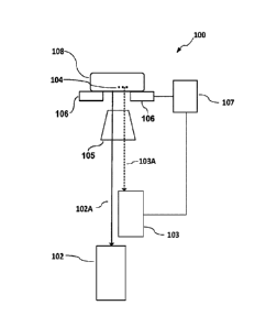
[0070] Figure lA is a block diagram showing a microscope 100 according to some
embodiments. Microscope 100 includes first and second imaging systems 102 and
103.
Imaging system 102 collects light from a sample 108 at a depth corresponding
to a first
focal plane F131. Imaging system 102 may perform super-resolution imaging.
Super-
resolution refers to a resolution better (i.e. finer) than the resolution
limit imposed by the
Abbe diffraction limit.
[0071] Imaging system 103 images one or more fiducial markers 104 at a depth
corresponding to a second focal plane FP2. Fiducial markers are features that
may be
tracked to monitor sample drift. Fiducial markers may be recognizable features
on or
within a sample, features built into a cover-slide or other sample support or
added markers
such as microbeads, nanoparticles or quantum dots. Fiducial markers may
optionally be
fluorescent. Fluorescent microbeads are convenient to use as fiducial markers.
Fiducial
markers may also be called 'fiducial elements'.
[0072] Imaging system 102 acquires light by way of an optical path 102A.
Imaging
system 103 acquires light by way of an optical path 103A. Optical paths 102A
and 103A
both pass through an objective lens 105.
13
CA 02991920 2018-01-10
WO 2016/168941
PCT/CA2016/050474
[0073] Sample 108 is mounted on a stage 106 that is movable in at least two
dimensions
(e.g. X and Y dimensions in a plane parallel to planes 14P1 and FP2). Stage
106 is
optionally movable in three dimensions (e.g. the X and Y dimensions and a Z
dimension
perpendicular to the X and Y dimensions). Stage 106 may, for example, be
controllably
positioned in two or three degrees of freedom by piezoelectric actuators.
Motions of stage
106 are controlled by a stage controller 107.
[0074] Imaging system 103 is configured to track motions of fiducial marker(s)
104 and to
provide feedback signals to stage controller 107 that cause stage 106 to move
in a way that
compensates for the observed motions.
[0075] Microscope 100 does not require that any fiducial markers 104 be within
the field
of view of first imaging system 102. In some embodiments focal planes FP1 and
FP2 are
separated by a distance that is greater than a depth of field provided by
objective lens 105.
[0076] Figure 1B is a flow chart illustrating an example image stabilization
method. Block
151 provides fiducial markers. Fiducial markers may, for example, comprise
fluorescent
microbeads and block 151 may comprise allowing the microbeads to adhere to a
coverslip.
[0077] In block 152 the sample and fiducial markers are illuminated.
Illumination may be
by light of one or more wavelengths. In block 153 light from the sample is
collected using
an optical system focused at a first focal plane. The light from the sample
may comprise
fluorescence light emitted as a result of the illumination provided in block
152.
[0078] Blocks 154, 155 and 156 are arranged to provide a real-time drift
compensation
loop 157. In block 154 light from the fiducial markers is collected using an
optical system
focused at a second focal plane. The optical system used to collect the light
from the
fiducial markers may be different from or the same as the optical system used
to collect
light from the sample in block 153.
[0079] In block 155, images acquired in block 154 are processed to determine
drift of the
fiducial markers. The processing may, for example, determine a location of one
or more
fiducial markers and compare that location to a previous location of the same
fiducial
marker (e.g. a previous location determined in a prior iteration of loop 157).
In an example
embodiment positions of one or more fiducial markers are compared to positions
of the
same fiducial marker(s) determined in a first iteration of block 155.
14
CA 02991920 2018-01-10
WO 2016/168941
PCT/CA2016/050474
[0080] In block 156 one or more actuators are controlled to move the sample
and fiducial
markers to compensate for the drift determined in block 155. In some
embodiments block
154 measures drift along each of a plurality of axes and block 155 controls a
corresponding plurality of actuators to move the sample along each of the
plurality of axes
by an amount sufficient to compensate for the drift. In some embodiments loop
157
repeats at a rate of at least a few Hz.
[0081] Figure 1C shows a microscope 160 according to a simple embodiment of
the
invention. Sample 1 contains a target element 2 which is of interest for
optical imaging.
Sample 1 is placed on a suitable transparent substrate such as a microscopy
coverslip 4.
[0082] Fiducial markers 5 are present, and may optionally be affixed to
coverslip 4.
[0083] Coverslip 4 is supported by a nano-positioning stage 21 that is capable
of
controlled movement in three-dimensions with nanometer precision.
[0084] A first light source 6 provides light 7 that is directed via dichroic
mirror 8 to
illuminate target element 2.
[0085] A second light source 9 provides light 10 that is directed via dichroic
minor 8 to
illuminate fiducial element 5.
[0086] Light 11 that may be reflected or emitted or fluoresced from target
element 2 is
directed by dichroic mirrors 8 and 12 to a sensor 13. Sensor 13 may for
example be a
camera. In some embodiments sensor 13 comprises a CCD camera.
[0087] Light 14 that may be reflected or emitted or fluoresced from fiducial
element 5 is
directed by dichroic mirrors 8 and 12 to a sensor 15. Sensor 15 may for
example be a
camera. In some embodiments sensor 15 comprises a CCD camera.
[0088] Light 14 is passed through a relay lens assembly 16 and 23, a tube lens
18 and an
asymmetrical lens such as a cylindrical lens assembly 17. Cylindrical lens
assembly 17
forms astigmatically aberrated images of the fiducial elements 5 on sensor 15.
The
astigmatically aberrated images may be processed to measure drift of the
fiducial elements
in a Z dimension parallel to an optical axis of objective lens 22. In this
manner 3D
positions of fiducial markers 5 can be established. The positions of fiducial
markers 5 so
calculated can be used in a closed feedback loop 19 to direct nano-positioning
stage
CA 02991920 2018-01-10
WO 2016/168941
PCT/CA2016/050474
controller 20 to move nanopositioning stage 21 and thereby correct for drift
of the sample
1 in the X, Y, and Z directions.
[0089] Images of target element 2 captured by sensor 13 may be brought into
focus using
objective lens 22. An image of fiducial markers 5 computed by sensor 15 can
then be
brought into focus by adjusting relay lens 16. This enables in-focus images of
both the
target element 2 and the fiducial markers 5 to be captured even though target
element 2
and fiducial markers 5 may be relatively widely separated in the Z direction.
[0090] Sample 1 may for example comprise a biological cell.
[0091] Figure ID is a flow chart illustrating another example image
stabilization method.
Block 181 provides fiducial markers. In some embodiments block 181 comprises
allowing fiducial markers to adhere to a coverslip.
[0092] In block 182 the sample and fiducial markers are illuminated.
Illumination may be
by light of one or more wavelengths. In block 183 an imaging system is focused
on a
fiducial marker plane, and the initial position of one or more fiducial
markers is
determined. In block 184 the imaging system is focused on the fiducial
markers, and their
current position is determined. In block 185 the current position of the
fiducial marker(s)
is compared to their initial position(s), and a drift of the fiducial markers
is calculated.
[0093] In block 186 an actuator is controlled to correct for the drift.
[0094] In block 187 the imaging system is focused on a sample plane, and in
block 188
the sample is imaged and the image is recorded. The light from the sample may
comprise
fluorescence light emitted as a result of the illumination provided in block
182.
[0095] In block 189, the method determines if the sample imaging is complete.
If so, the
method proceeded to block 191 and processes the recorded sample images. If
imaging is
not complete, the method repeats block 184 through to 188, until sample
imaging is
complete.
[0096] Figure 2A shows another example microscopy system 200 in which focal
planes of
the sample (target element) and fiducial marker(s) (fiducial element(s)) are
decoupled so
that imaging and tracking of the fiducial markers are independent of the depth
at which the
sample is being imaged.
16
CA 02991920 2018-01-10
WO 2016/168941
PCT/CA2016/050474
[0097] In system 200, sample 201 is imaged to CCD1 210, and fiducial markers
are
relayed to a separate camera CCD2 226. If the sample imaging depth is changed,
the
position of the relay imaging lens 220 may be adjusted to keep the fiducial
markers in
focus on CCD2 226. An astigmatism introduced into the optical path of the
fiducial
markers by compact lens 221 allows for precise 3D localization of the fiducial
marker(s).
Information regarding changes in the positions of the fiducial marker(s) is
used to stabilize
the sample position via a feedback loop 225.
[0098] The sample and fiducial markers are illuminated by light of one or more
wavelengths. As a result the sample and fiducial markers each emit light (by
reflecting the
incident light, fluorescing or some other mechanism). The light emitted by the
sample is
separable from the light emitted by the fiducial markers (e.g. the sample
emits light of a
first one or more wavelengths and the fiducial markers emit light of a second
one or more
wavelengths distinct from the first one or more wavelengths).
[0099] System 200 illustrates the possibility that light of different
wavelengths may be
applied to illuminate the sample and fiducial markers. In the illustrated
embodiment
illumination by two wavelengths causes the sample to emit light of a third
wavelength
(e.g. by exciting fluorescence in fluorophores of the sample). Illumination at
a fourth
wavelength causes the fiducial markers to emit light of a fifth wavelength
(e.g. by exciting
fluorescence in the fiducial markers).
[0100] In the illustrated embodiment a 635 nm laser 218 is used for exciting
fluorophores
in the sample, and a 405 nm laser 217 for re-activation. A 532 nm laser 216 is
used for
exciting the fiducial markers. Light from the lasers is combined using
dichroic mirrors 214
and 215, circularly polarized by a quarter-wave plate OA-) 212, and focused
and directed
into the back aperture of objective lens 203.
[0101] Fluorescence collected by objective lens 203 is filtered using a notch
filter 205 and
split by dichroic mirror 206. In the fiducial marker tracking path, a relay
lens assembly
220 and 223 transfers the image of fiducial markers (e.g. beads) into camera
CCD2 226. A
cylindrical lens assembly 221 introduces astigmatism enabling the 3D positions
of the
fiducial markers to be deteimined. Positions of the fiducial markers in the
images are used
in a closed feedback loop for 3D stabilization of the microscope stage. 231,
234 and 235
indicate the focal plane of the fiducial markers on CCD2 226.
17
CA 02991920 2018-01-10
WO 2016/168941
PCT/CA2016/050474
[0102] A cylindrical lens assembly 207 and a tube lens 209 are used to form
astigmatically aberrated images of fluorophores in the sample onto CCD1 210.
230, 232
and 233 indicate the focal plane of the sample on CCD1 220.
[0103] If the imaging depth of the sample is changed on CCD1 210, the position
of relay
lens assembly 220 may be adjusted to refocus the fiducial markers on CCD2 226.
The
fluorescent signals from the sample and fiducial markers respectively pass
through band-
pass filters 208 and 222 before entering CCD cameras 210 and 226.
[0104] Figures 2B, 2C and 2D respectively indicate the positions of the
fiducial markers
imaged using CCD1 in X, Y and Z axes in a prototype embodiment of the
invention.
Curves 250A, 251A and 252A show the position of the fiducial markers without
stabilization feedback. Curves 250B, 251B and 252B show the positions of the
fiducial
markers with stabilization feedback.
[0105] Without stabilization feedback, sample drifts in the range of a few
hundred nmn
over a period of 10 min are typical. With real-time 3D drift correction, the
sample drift is
limited to 0.7 nm (rms) in X (curve 250B) and Y (curve 251B) and 2.5 nm (rms)
in Z
(curve 252B).
[0106] Histograms 250C, 251C and 252C show the positional stability in each
direction.
The standard deviations are 0.7 nm in Y, 0.7 nm in Y and 2.6 nm in Z.
[0107] Some embodiments provide electronically tunable lenses (ETL) for
varying depths
of a sample focal plane and/or a fiducial marker focal plane. Figure 3 is
schematic
illustration showing a layout of an imaging system 300. Imaging system 300
comprises an
ETL that may be controlled to maintain fiducial markers in focus. In sonic
embodiments
the ETL is controlled automatically to keep the fiducial markers in focus.
[0108] In system 300 light of the same wavelength excites both fluorophores in
the sample
and the fiducial markers. For example, a 639 nm laser 321 may be used for
excitation of
fluorophores and fiducial markers and a 405 nm laser 320 may be used for
reactivation of
the fluorophores in the sample.
[0109] The diameters of the laser beams are adjusted using relay lenses 316,
317, 318 and
319. Beams from lasers 320 and 321 are combined using a dichroic mirror 315,
circularly
polarized by a quarter-wave plate 313, focused by a plano-convex lens 309 and
directed
18
CA 02991920 2018-01-10
WO 2016/168941
PCT/CA2016/050474
into the back aperture of objective lens 305. Mirrors 306 and 308 along with
plano-convex
lens 309 are positioned on a translation stage (not shown) to control an
incidence angle of
the excitation light.
[0110] A 3D piezo stage 304 controlled by a controller 339 is connected in a
feedback
mechanism loop 340.
[0111] Fluorescence collected by objective lens 305 is separated by dichroic
mirror 307
and filtered using notch filter 312. The fluorescence signals from the sample
and the
fiducial markers are separated using dichroic mirror 322. The fluorescence
signals
respectively pass through band-pass filters 325 and 335 before entering CCD
328 and 338.
[0112] In the fiducial marker tracking path fluorescence light passes through
a relay
system comprising tube lens 329 and relay lens 332. An electrically tunable
lens 333
extends the depth of field of objective lens 305 and refocuses the image of
the fiducial
marker(s) on CCD 338 even when imaging many micrometers deep within a sample.
[0113] A cylindrical lens assembly 334 is composed of a plano-convex and a
plano-
concave round cylindrical lens introduces astigmatism into the detection path,
enabling the
3D positions of the fiducial markers to be determined. These positions are
used in a closed
feedback loop for 3D stabilization of stage 304.
[0114] Cylindrical lens assembly 324 and tube lens 326 are used to form
astigmatically
aberrated images of the fluorophores in the sample onto EMCCD 328. 2.5X zoom
lens
323 is used to obtain an appropriate magnification of 150X on EMCCD 328. Focal
plane
302, 327 and 330 of the structure of interest is focused on EMCCD 328, and
focal plane
303 and 337 of the fiducial markers is focused on CCD 338.
[0115] Figure 4A is a schematic depiction of an example electrically tunable
lens based on
shape-changing polymer membrane technology.
[0116] Figure 4B shows axial focal shift as a function of current for an ETL
used in a
stabilization system.
[0117] Figure 4C is a schematic representation of a cylindrical lens compound,
which is
an example of an asymmetrical optical element that may be used to introduce an
astigmatic effect into the detection path of the fiducial markers.
19
CA 02991920 2018-01-10
WO 2016/168941
PCT/CA2016/050474
[0118] Figure 4D shows three x-y cross sections of an astigmatically aberrated
PSF at
different axial (Z-axis) positions.
[0119] Figure 4E shows the aspect ratio (R1y) of an astigmatic PSF as a
function of Z. The
black arrow shows the range of ellipticity which is used for tracking the
depth (Z-axis
position) of fiducial markers. This range provides sufficient sensitivity to
achieve high
accuracy tracking of fiducial markers in the axial direction.
[0120] Figures 5A, 5B and SC respectively show tracked positions of
fluorescent beads in
X, Y and Z dimensions over 10 min with the stabilization system (curves 500B,
501B and
502B) and without the stabilization system (curves 500A, 501A and 502A).
[0121] Figure 5D, 5E and 5F are respectively histograms of bead tracking
accuracy in X,
Y and Z directions. Standard deviations are 0.69 nm in X, 0.65 rim in Y and
2.71 nm in Z.
Four fiducial markers on the CCD are used for stabilizing the setup. The data
shown here
were obtained by analyzing the stability of three TetraSpeck" beads on the
EMCCD.
[0122] Figures 6A to 6L show the organization of transferrin receptors in a
drift-free
super-resolution image vs. a corresponding drifted image. Figure 6A is a STORM
image
of transferrin receptors in a B cell, obtained with the stabilization system,
and Figure 6B is
an image obtained without the stabilization system. Scale bars in both figures
are 2 gm.
[0123] Figure 6C shows the actual drift in the X 611, Y 610 and Z 612
directions that
occurred during STORM data acquisition.
[0124] Figures 6D and 6E are insets of the regions marked in Figures 6A and 6B
respectively. Scale bars in both figures are 500 nm.
[0125] Figures 6F and 6G are 3D representations of the regions marked in
Figures 6D and
6E respectively. Figures 6H and 61 are Voronol tessellation maps of regions
marked in
Figured 6D and 6E respectively. Shaded regions show the transferrin clusters
segmented
using density thresholding. Scale bars in figures 6F to 61 are 200 nm.
[0126] Figure 6J shows the cluster density in the drift-free image and the
drifted image.
[0127] Figure 6K shows the cluster diameter in the drift-free image and the
drifted image.
CA 02991920 2018-01-10
WO 2016/168941
PCT/CA2016/050474
[0128] Figure 6K shows the cluster circularity in the drift-free image and the
drifted
image.
Example Prototype Embodiments
[0129] A first prototype embodiment was made by customizing an inverted
microscope.
The prototype embodiment had the optical arrangement shown in Figure 2A. The
microscope was equipped with an apochromatic TIRF oil-immersion objective lens
(60X;
NA 1.49; Nikon Instruments, Melville, NY).
[0130] Separate illumination sources were used to cause emission of light from
the target
elements and to cause emission of light from fiducial markers. A 405 nm laser
(Thorlabs)
and a 639 nm laser (GenesisTM MX639, Coherent, Santa Clara, CA) were used for
excitation of target elements, which may be labeled using AlexaTM 647 dye
(Life
Technologies, Burlington, ON).
[0131] Excitation of fiducial markers (fluorescent beads) was provided by a
separate 532
nm laser (Excelsior OneTM, Spectra-Physics). Laser beams were collimated,
combined,
circularly polarized and focused into the back aperture of the objective lens.
[0132] A translational stage was used to shift the incident beam for either
oblique incident
excitation (deep imaging) or total internal reflection fluorescence imaging
(near-surface
imaging). A quad-band polychroic mirror (Di01-R205/488/532/636, Semrock) was
used to
reflect the excitation laser beams and transmit the fluorescence signals. A
long-pass
dichroic mirror (FF640-FDi01, Semrock) was utilized to separate fluorescence
emission of
the target element from fluorescence emissions from the fiducial markers.
[0133] In the detection path of target element, emission light passed through
a cylindrical
lens assembly 207, filtered by a band-pass filter (FF01-675/70, Semrock) and
finally
imaged to a back-illuminated CCD camera (iXon Ultra 897 BVTM, Andor) using a
200
mm achromatic doublet lens (ACA254-200-B, Thorlabs). A 2.5x magnifying lens
compound was placed before cylindrical lens assembly 207 to obtain an overall
magnification of 150x, which corresponds to a pixel size of 100 nm on CCD1
210.
[0134] A 100 mm achromatic doublet lens (AC254-100-A, Thorlabs) was placed in
the
detection path of the fiducial markers. This doublet lens functions as a relay
imaging lens
220. When the imaging depth is changed, the position of relay imaging lens 220
can be
21
CA 02991920 2018-01-10
WO 2016/168941
PCT/CA2016/050474
adjusted to keep the fiducial markers in focus on CCD2 226. A 250 mm
achromatic
doublet lens (AC254-250-A, Thorlabs) was used to form an image of fiducial
markers at
the back focal plane of relay imaging lens 220. The emission light then passed
through a
cylindrical lens assembly 221, filtered by a band-pass filter (H-01-562/40,
Semrock) and
finally imaged to CCD2 226 (Newton 970 IJBV, Andor) using a 200 mm achromatic
doublet lens (ACA254-200-B, Thorlabs).
[0135] Astigmatism was introduced into each optical path by, in each case, a
pair of 40
mm concave and -40 mm convex cylindrical lenses. This approach provides a
continuously variable astigmatic effect for obtaining the correct astigmatic
effect for deep
imaging.
[0136] To actively stabilize the microscope stage in 3D during the image
acquisition, up
to five different fiducial markers were used for tracking. Beads were
subsequently fitted
using an error function to determine their axial and lateral positions as
follows:
(x ¨ xo +0.5\ ¨ ¨0.5\\(erf (y ¨ yo +0.5
1(x,y) = A (erf ______________ erf ________
V7o-0 V7o-o -µ50-0
¨ yo ¨0.5\\
¨ erf ___________________________ + B
150-0
where I y) is the intensity, A is the amplitude and xo and yo are the emitter
positions in
lateral directions. cro and B are standard deviation and background noise,
respectively. By
taking the error-propagation-weighted average of calculated drifts for each
single fiducial
marker, an appropriate voltage was then sent to the piezo stage (Max311D,
Thorlabs)
using a 16-bit data acquisition card (PCI6323, National Instruments) and a
piezo-stage
controller (MDT693B, Thorlabs). Huang, F., Schwartz, S.L., Byars, J.M. &
Lidke, K.A.
Biomedical Optics Express 2, 1377-1393 (2011) describes one example way to
determine
drift from images of fiducial markers.
[0137] An exposure time of ¨200 ms was typically used for imaging the fiducial
markers.
With additional time of 1-2 ms for settling the piezo stage as well as ¨10 ms
for image
processing and fitting, drift correction was conducted at a rate of 4-5 Hz.
22
CA 02991920 2018-01-10
WO 2016/168941
PCT/CA2016/050474
[0138] To examine the performance of the active stabilization system,
positional stability
of 100 nm fluorescent beads on CCD1 was traced for 10 minutes. The results of
this
experiment are shown in Figure 2B.
[0139] Two different types of beads were mixed and affixed to the coverslip. A
mixture of
100nm TetraSpeckTm beads (T7279; Life Technologies, Burlington ON) at a
concentration
of 1 in 200, and 100 nm Orange FluoSpheresTM (F8800; excitation 540nm,
emission 560
nm, Life Technologies) at a concentration of 1 in 100000 were settled onto a
poly-L-lysine
coverslip overnight. The coverslip was rinsed to remove any beads that had not
firmly
attached and then mounted using a TN buffer (50 mMTris, 10 mMNaC1, pH 8). The
slide
was then mounted on the microscope stage and the cameras were synchronized.
[0140] Drift correction was conducted by tracking 100 nm Orange FluoSpheres
beads on
CCD2. TetraSpeck beads were simultaneously tracked on CCD1 for further
processing.
With active stabilization engaged, beads on CCD1 were locked within a standard
deviation
of 0.7 nm laterally and 2.6 nm axially over 10 min. The accuracy in axial
direction is
worse than that in lateral directions because the axial position is deduced
from widths of
elliptical PSF, which leads to an error accumulation.
Second Prototype Embodiment
[0141] A second prototype embodiment used an electronically-tunable lens. The
custom-
built STORM system of the first prototype embodiment was modified to
incorporate an
electrically tunable lens 333 as shown in Figure 3. The 639 nm laser was also
used for
excitation of 100 nm Infrared FluoSpheres (F8799, Life Technologies).
Activation of the
Alexa 647 fluorophores (i.e. increasing the transition rate of fluorophores
between dark
and bright states) was provided by a 405 nm laser (LRD 0405, Laserglow
Technologies,
Toronto, Canada).
[0142] Laser beams were collimated, combined, circularly polarized and focused
onto the
back aperture of the objective lens (318 and 319; AC127-030-A, 316 and 317;
AC127-
075-A, 315; FF560-FDi01, 313; AQWPO5M-600, 309; AC254-150-A, Thorlabs, Newton,
NJ). Mirror 306 and 308 were moved by a translation stage (PT1, Thorlabs) to
control
incident beam angle and to switch between epi-illumination and oblique
incident
illumination modes.
23
CA 02991920 2018-01-10
WO 2016/168941
PCT/CA2016/050474
[0143] A 3D piezo stage (Max311D, Thorlabs) equipped with a 16-bit digital-to-
analog
converter (PCI6323, National Instruments, Austin, TX) and a piezo-stage
controller
(MDT693B, Thorlabs) was used to locate the region of interest and stabilize
the
microscope during data acquisition. A quad-notch filter (312; 405/488/532/636,
Semrock)
was placed in the detection path to further block the excitation/activation
lasers. A short-
pass dichroic mirror (322; 1-1-720-1-M01, Semrock) was used to separate the
fluorescence
emission of Alexa 647 from that of the fiducial markers.
[0144] The detection path of the Alexa 647 contained a weak cylindrical lens
assembly
(324; effective focal length (EFL) = 10 m) composed of a plano-convex and a
plano-
concave round cylindrical lens with anti-reflection coating and focal lengths
of 400 mm
(LJ1363RM-B and LK1487RM-A, Thorlabs). Cylindrical lens assembly 324
introduced
astigmatism into the imaging path, creating slightly different focal planes in
the X and Y
directions. This resulted in elliptical PSFs for the fluorophores (i.e. the
ellipticity and
orientation of PSF varies along the optical axis). This allowed for the
decoding of the axial
positions of fluorophores within a few hundred nanometers above and below the
focal
plane of the objective lens 305. Concave and convex cylindrical lenses were
separated by
a distance, d.
[0145] The emission light was imaged to a back-illuminated electron
multiplying charge-
coupled device (328; iXon Ultra DU-897U, Andor, South Windsor, CT).
[0146] In the detection path of the fiducial markers, the emission light
passed through a
250 mm achromatic doublet lens (329; AC254-250-A, Thorlabs) followed by a
relay
imaging lens (332; AC254-100-A, Thorlabs). An electrically tunable lens (333;
EL-10-30-
Ci-VIS-LD, Optotune) was placed after the relay system such that it is
conjugate to the
back focal plane of the objective lens. The emitted light then passed through
a cylindrical
lens assembly (334; EFL = 2 m), which has a design analogous to that of 324;
The focal
lengths of the concave and convex components in 334 are 200 mm (LJ1653RM-B,
LK1069RM-A, Thorlabs). The emission light then passed through a band-pass
filter (335;
FF01-747/33, Semrock) and a 200 mm achromatic doublet lens (336; ACA254-200-B,
Thorlabs) before being imaged by the CCD (338; Newton 970 UBV, Andor).
[0147] In order to measure the performance of the active stabilization system,
a mixture of
100 nm TetraSpeck beads (T7279; Life Technologies) at a concentration of 1 in
200, and
24
CA 02991920 2018-01-10
WO 2016/168941
PCT/CA2016/050474
100 nm Infrared FluoSpheres (excitation 540nm; emission 560 nm) at a
concentration of 1
in 200000 were affixed onto a poly-L-lysine-coated coverslip. The coverslip
was then
rinsed to remove beads that had not firmly attached and mounted in phosphate-
buffered
saline. The 100 nm Infrared FluoSpheres were tracked on the CCD to provide
drift
correction feedback. TetraSpeck beads were simultaneously imaged on EMCCD to
measure the real stability of the imaging system.
[0148] Splenic B cells from 8-week old C57BL/6 mice were used. Splenic B cells
were
isolated, as described in S. A. Freeman, V. Jaumouille, K. Choi, B. E. Hsu, H.
S. Wong, L.
Abraham, M. L. Graves, D. Coombs, C. D. Roskelley, R. Das, S. Grinstein, and
M. R.
Gold, "Toll-like receptor ligands sensitize B-cell receptor signalling by
reducing actin-
dependent spatial confinement of the receptor," Nat Commun 6, 6168 (2015),
using a B
cell isolation kit (#19854, Stemcell Technologies) to deplete non-B cells. To
increase TfR
expression levels (J. Futran, J. D. Kemp, E. H. Field, A. Vora, and R. F.
Ashman,
"Transferrin receptor synthesis is an early event in B cell activation,"
Journal of
Immunology (Baltimore, Md.: 1950) 143, 787-792 (1989); L. M. Neckers, G.
Yenokida,
and S. P. James, "The role of the transferrin receptor in human B lymphocyte
activation,"
Journal of Immunology (Baltimore, Md.: 1950) 133, 2437-2441 (1984)). B cells
were
cultured in RPMI-1640 supplemented with 10% fetal calf serum, 2mM glutamine,
1mM
pyruvate, 50 jiM 2-mercaptoethanol, 50 U/mL penicillin and 50 g/mL
streptomycin
(complete medium) and stimulated with 5 jug/m1 E. cob 0111:B4 IPS (#L2630,
Sigma-
Aldrich catalogue) for 12 hr, as described in B. Huang, W. Wang, M. Bates, and
X.
Zhuang, "Three-Dimensional Super-Resolution Imaging by Stochastic Optical
Reconstruction Microscopy," Science 319, 810-813 (2008).
[0149] B cells were plated on coverslips (18 mm; #1.5H, Marienfeld,)
functionalized with
non-stimulatory M5/114 anti-MHCII monoclonal antibody (#12-5321, eBioscience)
for 10
min at 4 C, and subsequently fixed with ice cold 4% parafomialdehyde, 0.2%
glutaraldehyde in PBS for 90 min. Fixed cells were washed in PBS (3x),
permeabilized
with 0.1% Triton for 5 min after which they were washed in PBS again (3x). The
sample
was blocked in blocking buffer (10% noimal goat serum in PBS) for 1 hr at 4 C
and
subsequently stained with primary antibody (transferrin receptor; #13-6800,
Invitrogen)
overnight at 4 C. Cells were then washed in PBS (3x), incubated at room
temperature for
30 min with goat anti-mouse Alexa Fluor 647 (A21244, Life Technologies) and
then
CA 02991920 2018-01-10
WO 2016/168941
PCT/CA2016/050474
washed with PBS (5x) followed by a secondary fixation in 4% paraformaldehyde
for 10
min and a final series of PBS washes (5x). Fluorescent fiducial markers
(F8800, Life
Technologies) were incubated with the sample overnight at 4 C for the purpose
of sample
stabilization during image acquisition.
[0150] Imaging was performed in a standard GLOX-thiol solution (TN buffer [50
mM
Tris, 10 mM NaC1, pH 8.0], 0.5 mg/ml glucose oxidase, 401.tg/m1 catalase, 10%
(w/v)
glucose and 140 mM beta-mercaptoethanol). The coverslip along with the sample
were
mounted onto depression slides and sealed with the two-component silicone-glue
TwinsilTM (Picodent, Wipperflirth, Germany, #13001000).
[0151] The ETL used in this prototype stabilization system functions based on
the shape
changing principle. It has low dispersion in the visible range (wavefront
error < 0.25k) and
a focal length, fETL-fETL-fETLfETL, spanning from 200 mm to 100 mm (10 mm
aperture size;
C-mounted). It comprises a polymer membrane surrounded with a low dispersion
fluid on
one side and air on the other side, as shown in Figure 4A. The curvature of
the polymer
membrane increases (i.e. fETL decreases) as the current applied to the ETL is
increased;
conversely, fETL decreases by lowering the current. The whole system is
trapped between
two anti-reflection coated BK7 cover glasses and mounted using a stiff plastic
material (G.
Beadie, M. L. Sandrock, M. J. Wiggins, R. S. Lepkowicz, J. S. Shirk, M.
Ponting, Y.
Yang, T. Kazmierczak, A. Hiltner, and E. Baer, "Tunable polymer lens," Opt.
Express 16,
11847-11857 (2008); 0. Eberle, V. Chiron, and K. Wegener, "Simulation and
Realization
of a Focus Shifting Unit using a Tunable Lens for 3D Laser Material
Processing," Physics
Procedia 41, 441-447 (2013)).
[0152] A programmable lens driver equipped with a temperature sensor and a
drift
compensation mechanism was used to control the ETL. When the imaging depth was
changed, an appropriate current was applied to the ETL to tune fETL and keep
the fiducial
markers in focus on the CCD.
[0153] In order to characterize the dynamic behavior of the ETL, 100 nm
TetraSpeckTm
beads attached to the coverslip were used. Starting with the beads in focus on
the CCD
(i.e. when the ellipticity of the beads' PSFs = 1), an appropriate voltage was
applied to the
piezo stage to move the sample in the Z direction. The current was then
increased
gradually to bring the fluorescent beads back into focus on the CCD. Knowing
the actual
26
CA 02991920 2018-01-10
WO 2016/168941
PCT/CA2016/050474
shift of the sample in Z as well as the applied current, the relationship
between the control
current and the actual focal shift was obtained, as shown in Figure 4B.
Displacement of
the axial focal plane (Oz) was measured to be ¨11 jim when the control current
was
increased from 0 to 250 mA. Note that the ETL must be mounted horizontally to
avoid the
effect of gravity on its refractive power. Vertical mounting also induces a
significant
cornatic aberration into the detection path. The ETL should be aligned
precisely to ensure
that the magnification of the detection path is independent of the fETL.
Precise alignment
was achieved through an iterative process using a grid distortion test target
(R1L3S3P,
Thorlabs). fETL was changed to its maximum and minimum values and the grid
images
were recorded. The ETL was aligned such that the shift between the two images
was
insignificant. The response time of the ETL was measured to be less than 50
ms.
[0154] The ETL was paired with a weak cylindrical lens compound (334; focal
length:
fcL2) to introduce an adaptive astigmatic effect into the imaging path of the
fiducial
markers. Cylindrical lens 334 is composed of a plano-convex and a plano-
concave round
cylindrical lens with focal lengths (fa) of 200 mm, separated from each other
by a
distance d, as shown in Figure 4C. It is simpler and more cost effective
compared to
previously proposed methods based on a deformable mirror array (I. Izeddin, M.
El
Beheiry, J. Andilla, D. Ciepielewski, X. Darzacq, and M. Dahan, "PSF shaping
using
adaptive optics for three-dimensional single-molecule super-resolution imaging
and
tracking," Opt. Express 20, 4957 (2012); N. Piro, T. Pengo, N. Olivier, and S.
Manley,
"Improved 3D Superresolution Localization Microscopy Using Adaptive Optics,"
arXiv:1401.0879 [physics] (2014)). The cylindrical lens compound allows for
optimization of the depth-dependent astigmatic effect by varying the distance
between the
two cylindrical components. Therefore, one can achieve an axial localization
accuracy
down to a few nanometers when tracking beads to stabilize the microscope at
any imaging
depth that the depth of field allows. For instance, Figures 4D and 4E show an
optimized
astigmatism effect used to track fluorescent beads when imaging at a depth of
8 p.m (d =
mm). To achieve a good sensitivity, d was adjusted such that moving the beads
along
the Z direction from +200 nm to -200 nm changes their ellipticity on the CCD
from 1.5 to
0.75.
[0155] Generally, Sz is inversely proportional to the effective focal length
of the ETL,
fETL,ef f and is given by F. 0. Fahrbach, F. F. Voigt, B. Schmid, F.
IIelmchen, and J.
27
CA 02991920 2018-01-10
WO 2016/168941
PCT/CA2016/050474
Huisken, "Rapid 3D light-sheet microscopy with a tunable lens," Opt. Express
21, 21010
(2013), where n is the refractive index of the immersion medium, fRL2 is the
focal length
of relay lens 536 and M is the magnification on the CCD. f
ETL,e f f can be expressed as
fETL,eff-1 = fETL-1 fCL2 -1 ¨ dfETL -11CL2 -1 ' fETL-1 fCL2-1. Cylindrical
lens 334
can be considered as an anamorphic Fourier transform system (I. Moreno, C.
Ferreira, and
M. M. Sanchez-Lopez, "Ray matrix analysis of anamorphic fractional Fourier
systems," J.
Opt. A: Pure Appl. Opt. 8, 427 (2006); T. Szoplik, W. Kosek, and C. Ferreira,
"Nonsymmetric Fourier transforming with an anamorphic system," Appl. Opt. 23,
905
(1984)) with a ray matrix in the X direction (ScL2,,) given by:
) (1 d\( 1 0 \
SCL2,x = (cc 1 0
-1 1) 1) ¨f. -1 1 )
c t
= (1 ¨ d fci-1 1 (1)
¨dfci-2 1 + dfc1-
1)'
which gives fcL2 = . In
principle, the ray matrix for an individual cylindrical lens
s(a) sin(a))
depends on a rotation matrix given by R (a) = co , where
a is the angle
¨sin(a) cos(a)
between the direction of the lens curvature and x-axis (in case of cylindrical
lens 334, a =
0 so R (a) = I).
[0156] 8z for the current system was calculated as 12.6 iirn, which is very
close to the
experimental measurement (< 10% difference). The actual focal shift of -11
f..tm was
sufficient for imaging the transferrin receptors within B cells; the largest B
cell which was
observed had a thickness of -10 p.m. In addition, imaging at a depth larger
than that
greatly suffers from the sample-induced aberration and light scattering, which
degrades
the quality of the PSFs of single molecules. Note that Oz can be easily
extended by four
times if one decreases M by two times (i.e. M = 75).
[0157] In order to examine the performance of the stabilization system, the
positional
stability of 100 nm TetraSpeckTm beads was measured on EMCCD 328 for 10 min.
Cameras were synchronized to obtain simultaneous exposure and readout on them.
CCD
338 was set to acquire images at a rate of -3 frames per second (exposure time
= 300 ms,
piezo stage settling time = 20 ms). Five Infrared fiducial marker located
close to the center
of the frame were tracked on CCD 338 to provide drift correction feedback.
TetraSpeck
28
CA 02991920 2018-01-10
WO 2016/168941
PCT/CA2016/050474
beads were simultaneously imaged on EMCCD 328. A region of interest (ROI = 10
pixel
x 10 pixel) was set around each individual bead and ROIs were subsequently
fitted using
an error function to determine the lateral position of the beads as follows
(x ¨ xo + 0.5) (x ¨ xo ¨ 0.5))
Ik(X, y) = lo(erf erf ______
)
(2)
Y Yo + 0.5) (y ¨ yo ¨ 0.5))
x (erf( erf _________ + bo,
Aao-y
where /k (x, y) is the expected number of photons for a given pixel k, 10 is
the total number
of photons and xo and yo are the emitter positions in lateral directions. a,
and ay are the
standard deviations of the error function in X and Y, respectively, and 1)0 is
the
background noise. The ellipticity, Rxy = ax / ay, was then calculated to
determine the
axial position of a bead according to the calibration curve shown in Figure
4E.
Displacement of beads was subsequently determined by comparing their shifted
and initial
positions. The mean of the displacements was then calculated and an
appropriate voltage
was applied to the piezo stage through a feedback loop.
[0158] Figure 5A shows the positional stability of 100 nm TetraSpeckTm beads
on
EMCCD 528 with respect to time. Without the drift-correcting feedback
mechanism loop
enabled, the system drifts ¨100 nm in the lateral direction and ¨150 nm in the
axial
direction as measured over 10 min. With the feedback loop, however, the sample
was
stabilized in real-time and in three dimensions down to a few nanometers.
Figure 5B
shows the root-mean-square (rms) of the beads' position, which was measured to
be ¨0.7
nm in the X 500C and Y 501C directions and ¨2.7 nm n in the Z 502C direction.
The error
in bead localization arises from the asymmetric emission profile of
fluorescent beads, non-
linearity in the photoelectric response of the camera and the associated
computational
errors. Note that the error in Z is about four times larger than that in X and
Y. This is due
to error propagation, which occurs by estimating the axial position of a bead
using the
widths of its PSF in X and Y directions, i.e. W., and W.
Super-resolution imaging of transferrin receptors in B cells
[0159] To demonstrate the application of the real-time 3D stabilization
system, transferrin
receptors in B cells were imaged at a depth of 8 pm. The transferrin receptor
(TfR) is a
membrane glycoprotein and mediates cellular uptake of iron from a plasma
glycoprotein,
29
CA 02991920 2018-01-10
WO 2016/168941
PCT/CA2016/050474
transferrin. Iron uptake from transferrin involves the binding of transferrin
to the TfR,
internalization of transferrin within an endocytic vesicle by receptor-
mediated endocytosis
and the subsequent release of iron from the protein induced by a decrease in
endosomal
pH (P. Ponka and C. N. Lok, "The transferrin receptor: role in health and
disease," The
International Journal of Biochemistry & Cell Biology 31, 1111-1137 (1999)). In
cell
biology, TfR is a prototype marker for the recycling pathways and to probe
both cell
surface and endosornal structures in cells (H. Kobayashi and M. Fukuda, "Arf6,
Rabl 1
and transferrin receptor define distinct populations of recycling endosomes,"
Commun.
Integr. Biol. 6, e25036 (2013); R. S. Ajioka and J. Kaplan, "Intracellular
pools of
transferrin receptors result from constitutive internalization of unoccupied
receptors,"
Proc. Natl. Acad. Sci. U.S.A. 83, 6445-6449 (1986); E. M. v. Dam, T. t.
Broeke, K.
Jansen, P. Spijkers, and W. Stoorvogel, "Endocytosed Transferrin Receptors
Recycle via
Distinct Dynamin and Phosphatidylinositol 3-Kinase-dependent Pathways," J.
Biol. Chem.
277, 48876-48883 (2002)). This makes TfR an ideal choice for demonstrating the
application of the stabilization system in deep super-resolution imaging.
[0160] The 639 nm laser was used at a relatively low intensity (< 2 Wicm2 at
the sample)
for illumination. A region of interest deep within the cell was located and
the actual
imaging depth was measured using the piezo stage controller. Before turning on
the
feedback mechanism loop, an appropriate current was applied to the ETL through
the lens
drive to obtain a clear image of the fiducial markers on the CCD. The current
was adjusted
such that the beads' ellipticity was in the range of 0.75-1.5. Up to five
fiducial markers
were typically tracked during image acquisition at a rate of 3 frames per
second (fps).
[0161] Exposure time and gain of the CCD were gradually increased to
compensate for
the continuously decreasing number of photons emitted by infrared fluorescent
beads. This
ensures consistent accuracy in 3D localization of fiducial markers during the
course of
image acquisition. The intensity of the 639 nm laser was then increased to ¨5
kW/cm2 and
the sample was photobleached for ¨30 s. 40,000 frames were typically acquired
on the
EMCCD, at a rate of ¨50 fps, to accumulate a sufficient number of single-
molecule
localizations. To reactivate dye molecules and compensate for a decreasing
number of
blinks due to photobleaching, the intensity of the 405 nm laser was increased
in a stepwise
fashion (from 0 to ¨1 W/cm2) during image acquisition. The post-acquisition
processing of
images to determine the positions of single-molecules was performed using
software
CA 02991920 2018-01-10
WO 2016/168941
PCT/CA2016/050474
written in MATLAB, as described in R. Tafteh, D. R. L. Scriven, E. D. W.
Moore, and K.
C. Chou, "Single molecule localization deep within thick cells; a novel super-
resolution
microscope," J. Biophoton 9, 155-160 (2016).
[0162] A drift-free super-resolution image of transferrin receptors in a B
cell is shown in
Figure 6A. This image was constructed by plotting the density map of single-
molecule
localizations (nearest neighborhood distance (NND) = 100 nm). The
corresponding image
with drift is shown in Figure 6B. This was obtained by computationally adding
the actual
drift in all directions that occurred during image acquisition to the drift-
free image, as
shown in Figure 6C. Insets of the regions as marked in Figures 6A and 6B are
shown in
Figure 6D and 6E, respectively. The drift-free super-resolution image shown in
Figure 6D
reveals that transferrin receptors exist as well-defined clusters, which are
punctate with a
significantly higher density compared to the corresponding clusters in the
drifted image
shown in Figure 6E. Specifically, clusters in the drifted image are elongated
and blurred.
The three-dimensional representations of regions marked in Figured 6D and 6E
in are
shown in Figure 6F and 6G, respectively. The clusters in the drift-free super-
resolution
image shown in Figure 6F are isotropic and distinct from cluster to cluster.
However, the
corresponding clusters in the drifted image shown in Figure 6G are non-
isotropic and
difficult to discern as they are fused together.
[0163] To quantitatively analyze the effects of drift on topology and density
of TfR
clusters, a novel clustering method based on Voronoi tessellation was used (F.
Levet, E.
Hosy, A. Kechkar, C. Butler, A. Beghin, D. Choquet, and J.-B. Sibarita, "SR-
Tesseler: a
method to segment and quantify localization-based super-resolution microscopy
data,"
Nat. Methods 12, 1065-1071 (2015); D. Baddeley, "Detecting nano-scale protein
clustering," Nat. Methods 12, 1019-1020 (2015)). Voronof tessellation is based
on the
principle of subdividing an image into polygonal regions centered on seeds.
Any point
within a polygon is closer to its associated seed than it is to any other
seed. Figures 6H and
61 show tessellation maps of the regions as marked in Figured 6D and 6E
respectively;
segmented clusters are shaded. Segmentation of the localization data points
into clusters
was performed using a single parameter, i.e. density threshold, which was set
to twice the
average localization density. Comparing the regions marked by dashed lines in
Figures 6H
and 61, one can see that drift not only affects the separation of the closely
spaced
transferrin clusters as between regions 610A and 611A, and between regions
610B and
31
CA 02991920 2018-01-10
WO 2016/168941
PCT/CA2016/050474
611B, but it also affects the topology of the clusters (compare the clusters
in region 610C
with 611C).
[0164] A more comprehensive analysis of transferrin clusters in Figures 6J and
6K reveals
that drift has significant influences on the distribution of cluster density
(i.e. number of
localization per cluster per unit area, and cluster size). Overall, the TfR
clusters in the
drift-free image are smaller than those in the drifted image and show higher
cluster
density. This is attributed to the sample drift, which extends the area of
clusters and leads
to a lowered cluster density. TfR exist as heterogeneous nanoclusters in B
cells (as shown
by bimodal size distribution in Figure 6K). This data is consistent with
electron
microscopy (EM) studies, which show that size of TfR containing vesicles
varies from 30
nal to 160 nm (R. S. Ajioka and J. Kaplan, "Intracellular pools of transferrin
receptors
result from constitutive internalization of unoccupied receptors," Proc. Natl.
Acad. Sci.
U.S.A. 83, 6445-6449 (1986); C. Harding, J. Heuser, and P. Stahl, "Receptor-
mediated
endocytosis of transferrin and recycling of the transferrin receptor in rat
reticulocytes,"
The Journal of Cell Biology 97, 329-339 (1983); C. R. Hopkins, "Intracellular
routing of
transferrin and transferrin receptors in epidermoid carcinoma A431 cells,"
Cell 35, 321-
330 (1983); B. T. Pan, K. Teng, C. Wu, M. Adam, and R. M. Johnstone, "Electron
microscopic evidence for externalization of the transferrin receptor in
vesicular form in
sheep reticulocytes," The Journal of Cell Biology 101, 942-948 (1985)).
[0165] Figure 6L shows distribution of the cluster circularity shows that
transferrin
clusters in the drift-free super-resolution image are more circular compared
to those in the
drifted image. Cluster circularity was calculated as the ratio of the major
and minor axes
of a cluster. The majority of UR clusters in the drifted image have a
circularity of 0.5,
compared to 0.75 in the drift-free image.
Interpretation of Terms
[0166] Unless the context clearly requires otherwise, throughout the
description and the
claims:
= "comprise", "comprising", and the like are to be construed in an
inclusive sense, as
opposed to an exclusive or exhaustive sense; that is to say, in the sense of
"including, but not limited to";
32
CA 02991920 2018-01-10
WO 2016/168941
PCT/CA2016/050474
= "connected", "coupled", or any variant thereof, means any connection or
coupling,
either direct or indirect, between two or more elements; the coupling or
connection
between the elements can be physical, logical, or a combination thereof;
= "herein", "above", "below", and words of similar import, when used to
describe
this specification, shall refer to this specification as a whole, and not to
any
particular portions of this specification;
= "of', in reference to a list of two or more items, covers all of the
following
interpretations of the word: any of the items in the list, all of the items in
the list,
and any combination of the items in the list;
= the singular forms "a", "an", and "the" also include the meaning of any
appropriate
plural forms;
= "optical radiation" refers to electromagnetic radiation in the wavelength
range of
100 nm to 1 mm;
= "deep imaging" is imaging at least 1 p.m deep in a sample.
[0167] Words that indicate directions such as "vertical", "transverse",
"horizontal",
"upward", "downward", "forward", "backward", "inward", "outward", "vertical",
"transverse", "left", "right", "front", "back", "top", "bottom", "below",
"above", "under",
and the like, used in this description and any accompanying claims (where
present),
depend on the specific orientation of the apparatus described and illustrated.
The subject
matter described herein may assume various alternative orientations.
Accordingly, these
directional terms are not strictly defined and should not be interpreted
narrowly.
[0168] Embodiments of the invention may be implemented using specifically
designed
hardware, configurable hardware, programmable data processors configured by
the
provision of software (which may optionally comprise "firmware") capable of
executing
on the data processors, special purpose computers or data processors that are
specifically
programmed, configured, or constructed to perform one or more steps in a
method as
explained in detail herein and/or combinations of two or more of these. Such
hardware
may be configured for example to provide closed-loop control of a stage and/or
image
processing as described herein. Examples of specifically designed hardware
are: logic
circuits, application-specific integrated circuits ("ASICs"), large scale
integrated circuits
("LSIs"), very large scale integrated circuits ("VLSIs"), and the like.
Examples of
33
CA 02991920 2018-01-10
WO 2016/168941
PCT/CA2016/050474
configurable hardware are: one or more programmable logic devices such as
programmable array logic ("PALs"), programmable logic arrays ("PLAs"), and
field
programmable gate arrays ("FPGAs")). Examples of programmable data processors
are:
microprocessors, digital signal processors ("DSPs"), embedded processors,
graphics
processors, math co-processors, general purpose computers, server computers,
cloud
computers, mainframe computers, computer workstations, and the like. For
example, one
or more data processors in a control circuit for a device may implement
methods as
described herein by executing software instructions in a program memory
accessible to the
processors.
[0169] Processing may be centralized or distributed. Where processing is
distributed,
information including software and/or data may be kept centrally or
distributed. Such
information may be exchanged between different functional units by way of a
communications network, such as a Local Area Network (LAN), Wide Area Network
(WAN), or the Internet, wired or wireless data links, electromagnetic signals,
or other data
communication channel.
[0170] For example, while processes or blocks are presented in a given order,
alternative
examples may perform routines having steps, or employ systems having blocks,
in a
different order, and some processes or blocks may be deleted, moved, added,
subdivided,
combined, and/or modified to provide alternative or subcombinations. Each of
these
processes or blocks may be implemented in a variety of different ways. Also,
while
processes or blocks are at times shown as being performed in series, these
processes or
blocks may instead be performed in parallel, or may be performed at different
times.
[0171] Software and other modules may reside on servers, workstations,
personal
computers, microscope controllers, and other devices suitable for the purposes
described
herein. Those skilled in the relevant art will appreciate that aspects of the
system can be
practised with other communications, data processing, or computer system
configurations.
[0172] Where a component (e.g. a software module, processor, assembly, device,
circuit,
etc.) is referred to above, unless otherwise indicated, reference to that
component
(including a reference to a "means") should be interpreted as including as
equivalents of
that component any component which performs the function of the described
component
(i.e., that is functionally equivalent), including components which are not
structurally
34
CA 02991920 2018-01-10
WO 2016/168941
PCT/CA2016/050474
equivalent to the disclosed structure which performs the function in the
illustrated
exemplary embodiments of the invention.
[0173] Specific examples of systems, methods and apparatus have been described
herein
for purposes of illustration. These are only examples. The technology provided
herein
can be applied to systems other than the example systems described above. Many
alterations, modifications, additions, omissions, and permutations are
possible within the
practice of this invention. This invention includes variations on described
embodiments
that would be apparent to the skilled addressee, including variations obtained
by:
replacing features, elements and/or acts with equivalent features, elements
and/or acts;
mixing and matching of features, elements and/or acts from different
embodiments;
combining features, elements and/or acts from embodiments as described herein
with
features, elements and/or acts of other technology; and/or omitting combining
features,
elements and/or acts from described embodiments.
[0174] It is therefore intended that the following appended claims and claims
hereafter
introduced are interpreted to include all such modifications, permutations,
additions,
omissions, and sub-combinations as may reasonably be inferred. The scope of
the claims
should not be limited by the preferred embodiments set forth in the examples,
but should
be given the broadest interpretation consistent with the description as a
whole.
[0175] The following references relate generally to the field of the
disclosure and include
information that provides background for better understanding of the
invention:
1. Pertsinidis, A., Zhang, Y. & Chu, S. Nature 466, 647-651 (2010).
2. Carter, A.R. et al. Appl. Opt. 46, 421-427 (2007).
3. Mennella, V. et al. Nat. Cell Biol. 14, 1159-1168 (2012).
4. Geisler, C. et al. Opt. Express 20 (2012).
5. Huang, B., Jones, S.A., Brandenburg, B. & Zhuang, X. Nat. Meth. 5, 1047-
1052
(2008).
6. Huang, B., Wang, W., Bates, M. & Zhuang, X. Science 319, 810-813 (2008).
7. McGorty, R., Schnitzbauer, J., Zhang, W. & Huang, B. Opt. Lett. 39, 275-278
(2014.)
8. Henriques, R. et al. Nat. Meth. 7, 339-340 (2010).
9. Wolter, S. et al. Nat. Meth. 9, 1040-1041 (2012).
CA 02991920 2018-01-10
WO 2016/168941
PCT/CA2016/050474
10. Jones, S.A., Shim, S.-H., He, J. & Zhuang, X. Nat. Meth. 8, 499-505
(2011).
11. Chen-lzu, Y. et al. Biophys. J. 91, 1-13 (2006).
12. Babcock, H., Sigal, Y.M. & Zhuang, X. Opt. Nanoscopy 1 (2012).
13. Cox, S. et al. Nat. Meth. 9, 195-200 (2012).
14. Holden, S.J., Uphoff, S. & Kapanidis, A.N. Nat. Meth. 8, 279-280 (2011).
15. Radennacher, M. et al. J. Cell Biol. 127, 411-423 (1994).
16. Asghari, P. et al. Circ. Res. 115, 252-262 (2014).
17. Huang, F., Schwartz, S.L., Byars, J.M. & Lidke, K.A. Biomedical Optics
Express
2, 1377-1393 (2011)
18. Pertsinidis, A., Zhang, Y. & Chu, S. Subnanometre single-molecule
localization,
registration and distance measurements. Nature 466, 647-651 (2010)
19. Chen-lzu, Y. et al. Biophysical Journal 91, 1-13 (2006)
20. Rodrigues, B.a.S., D.L. Preparation of cardiomyocytes. (CRC Press, 1997)
21. Volkmann, H., "Ernst Abbe and His Work," Appl. Opt. 5, 1720 (1966).
22. Rayleigh, L., "XV. On the theory of optical images, with special reference
to the
microscope," Philosophical Magazine Series 5 42, 167-195 (1896).
23. Cremer, C. and Masters, B. R., "Resolution enhancement techniques in
microscopy," ERI H 38, 281-344 (2013).
24. McCutchen, C.W., "Superresolution in Microscopy and the Abbe Resolution
Limit," J. Opt. Soc. Am. 57, 1190 (1967).
25. Yildiz, A., Forkey, J. N., McKinney, S. A., Ha, T., Goldman, Y. E., and
Selvin, P.
R., "Myosin V walks hand-over-hand: single fluorophore imaging with 1.5-nm
localization," Science (New York, N.Y.) 300, 2061-2065 (2003).
26. Yildiz, A., Tomishige, M., Vale, R. D., and Selvin, P. R., "Kinesin walks
hand-
over-hand," Science (New York, N.Y.) 303, 676-678 (2004).
27. Betzig, E., Patterson, G. H., Sougrat, R., Lindwasser, 0.W., Olenych, S.,
Bonifacino, J. S., Davidson, M. W., Lippincott-Schwartz, J., and Hess, II. F.,
"Imaging Intracellular Fluorescent Proteins at Nanometer Resolution," Science
313, 1642-1645 (2006).
28. Rust, M. J., Bates, M., and Zhuang, X., "Sub-diffraction-limit imaging by
stochastic optical reconstruction microscopy (STORM)," Nat. Methods 3, 793-796
(2006).
36
CA 02991920 2018-01-10
WO 2016/168941
PCT/CA2016/050474
29. G. Giannone, E. Hosy, F. Levet, A. Constals, K. Schulze, A. I. Sobolevsky,
M. P.
Rosconi, E. Gouaux, R. Tampe, D. Choquet, and L. Cognet, "Dynamic
superresolution imaging of endogenous proteins on living cells at ultra-high
density," Biophys. J. 99, 1303-1310 (2010).
30. R. J. Ober, S. Ram, and E. S. Ward, "Localization Accuracy in Single-
Molecule
Microscopy," Biophys. J. 86, 1185-1200 (2004).
31. S. H. Lee, M. Baday, M. Tjioe, P. D. Simonson, R. Zhang, E. Cai, and P. R.
Selvin, "Using fixed fiducial markers for stage drift correction," Opt.
Express 20,
12177-12183 (2012).
32. A. Pertsinidis, Y. Zhang, and S. Chu, "Subnanometre single-molecule
localization,
registration and distance measurements," Nature 466, 647-651 (2010).
33. A. R. Carter, G. M. King, T. A. Ulrich, W. Halsey, D. Alchenberger, and T.
T.
Perkins, "Stabilization of an optical microscope to 0.1 nm in three
dimensions,"
Appl. Opt. 46, 421-427 (2007).
34. R. McGorty, D. Kamiyama, and B. Huang, "Active microscope stabilization in
three dimensions using image correlation," in Opt. Nanoscopy, (2013).
35. V. Mennella, B. Keszthelyi, K. L. McDonald, B. Chhun, F. Kan, G. C.
Rogers, B.
Huang, and D. A. Agard, "Subdiffraction-resolution fluorescence microscopy
reveals a domain of the centrosome critical for pericentriolar material
organization," Nat. Cell Biol. 14, 1159-1168 (2012).
36. C. Geisler, T. Hotz, A. Schonle, S. W. Hell, A. Munk, and A. Egner, "Drift
estimation for single marker switching based imaging schemes," Opt. Express 20
(2012).
37. M. J. Mlodzianoski, J. M. Schreiner, S. P. Callahan, K. Smolkova, A.
Dlaskova, J.
Santorova, P. JeIek, and J. Bewersdorf, "Sample drift correction in 3D
fluorescence photoactivation localization microscopy," Opt. Express 19, 15009-
15019 (2011).
38. G. Beadie, M. L. Sandrock, M. J. Wiggins, R. S. Lepkowicz, J. S. Shirk, M.
Ponting, Y. Yang, T. Kazmierczak, A. Hiltner, and E. Baer, "Tunable polymer
lens," Opt. Express 16, 11847-11857 (2008).
39. H. Ren, H. Xianyu, S. Xu, and S.-T. Wu, "Adaptive dielectric liquid lens,"
Opt.
Express 16, 14954 (2008).
37
CA 02991920 2018-01-10
WO 2016/168941
PCT/CA2016/050474
40. 0. Pishnyak, S. Sato, and 0. D. Lavrentovich, "Electrically tunable lens
based on a
dual-frequency nematic liquid crystal," Appl. Opt. 45, 4576 (2006).
41. S. Kuiper, B. H. Hendriks, L. J. Huijbregts, A. M. Hirschberg, C. A.
Renders, and
M. A. van As, "Variable-focus liquid lens for portable applications," in 2004,
100-
109.
42. R. Tafteh, D. R. L. Scriven, E. D. W. Moore, and K. C. Chou, "Single
molecule
localization deep within thick cells; a novel super-resolution microscope," J.
Biophoton 9, 155-160 (2016).
43. B. Huang, W. Wang, M. Bates, and X. Zhuang, "Three-Dimensional Super-
Resolution Imaging by Stochastic Optical Reconstruction Microscopy," Science
319, 810-813 (2008).
44. S. A. Freeman, V. Jaumouille, K. Choi, B. E. Hsu, H. S. Wong, L. Abraham,
M. L.
Graves, D. Coombs, C. D. Roskelley, R. Das, S. Grinstein, and M. R. Gold,
"Toll-
like receptor ligands sensitize B-cell receptor signalling by reducing actin-
dependent spatial confinement of the receptor," Nat Commun 6, 6168 (2015).
45. J. Futran, J. D. Kemp, E. H. Field, A. Vora, and R. F. Ashman,
"Transferrin
receptor synthesis is an early event in B cell activation," Journal of
Immunology
(Baltimore, Md.: 1950) 143, 787-792 (1989).
46. L. M. Neckers, G. Yenolcida, and S. P. James, "The role of the transferrin
receptor
in human B lymphocyte activation," Journal of Immunology (Baltimore, Md.:
1950) 133, 2437-2441 (1984).
47. G. Eberle, V. Chiron, and K. Wegener, "Simulation and Realization of a
Focus
Shifting Unit using a Tunable Lens for 3D Laser Material Processing," Physics
Procedia 41, 441-447 (2013).
48. I. Izeddin, M. El Beheiry, J. Andilla, D. Ciepielewski, X. Darzacq, and M.
Dahan,
"PSF shaping using adaptive optics for three-dimensional single-molecule super-
resolution imaging and tracking," Opt. Express 20, 4957 (2012).
49. N. Piro, T. Pengo, N. Olivier, and S. Manley, "Improved 3D Superresolution
Localization Microscopy Using Adaptive Optics," arXiv:1401.0879 [physics]
(2014).
50. F. 0. Fahrbach, F. F. Voigt, B. Schmid, F. Helmchen, and J. Huisken,
"Rapid 3D
light-sheet microscopy with a tunable lens," Opt. Express 21, 21010 (2013).
38
CA 02991920 2018-01-10
WO 2016/168941
PCT/CA2016/050474
51. I. Moreno, C. Ferreira, and M. M. Sanchez-Lopez, "Ray matrix analysis of
anamorphic fractional Fourier systems," J. Opt. A: Pure App!. Opt. 8, 427
(2006).
52. T. Szoplik, W. Kosek, and C. Ferreira, "Nonsymmetric Fourier transforming
with
an anamorphic system," App!. Opt. 23, 905 (1984).
53. P. Ponka and C. N. Lok, "The transferrin receptor: role in health and
disease," The
International Journal of Biochemistry & Cell Biology 31, 1111-1137 (1999).
54. H. Kobayashi and M. Fukuda, "Arf6, Rabl 1 and transferrin receptor define
distinct
populations of recycling endosomes," Commun. Integr. Biol. 6, e25036 (2013).
55. R. S. Ajioka and J. Kaplan, "Intracellular pools of transferrin receptors
result from
constitutive internalization of unoccupied receptors," Proc. Natl. Acad. Sci.
U.S.A.
83, 6445-6449 (1986).
56. E. M. v. Dam, T. t. Broeke, K. Jansen, P. Spijkers, and W. Stoorvogel,
"Endocytosed Transferrin Receptors Recycle via Distinct Dynamin and
Phosphatidylinositol 3-Kinase-dependent Pathways," J. Biol. Chem. 277, 48876-
48883 (2002).
57. F. Levet, E. Hosy, A. Kechkar, C. Butler, A. Beghin, D. Choquet, and J.-B.
Sibarita, "SR-Tesseler: a method to segment and quantify localization-based
super-
resolution microscopy data," Nat. Methods 12, 1065-1071 (2015).
58. D. Baddeley, "Detecting nano-scale protein clustering," Nat. Methods 12,
1019-
1020 (2015).
59. C. Harding, J. Heuser, and P. Stahl, "Receptor-mediated endocytosis of
transferrin
and recycling of the transferrin receptor in rat reticulocytes," The Journal
of Cell
Biology 97, 329-339 (1983).
60. C. R. Hopkins, "Intracellular routing of transferrin and transferrin
receptors in
epidermoid carcinoma A431 cells," Cell 35, 321-330 (1983).
61. B. T. Pan, K. Teng, C. Wu, M. Adam, and R. M. Johnstone, "Electron
microscopic
evidence for externalization of the transferrin receptor in vesicular form in
sheep
reticulocytes," The Journal of Cell Biology 101, 942-948 (1985).
39