Language selection

Search

Patent 2991945 Summary

Third-party information liability

Some of the information on this Web page has been provided by external sources. The Government of Canada is not responsible for the accuracy, reliability or currency of the information supplied by external sources. Users wishing to rely upon this information should consult directly with the source of the information. Content provided by external sources is not subject to official languages, privacy and accessibility requirements.

Claims and Abstract availability

Any discrepancies in the text and image of the Claims and Abstract are due to differing posting times. Text of the Claims and Abstract are posted:

  • At the time the application is open to public inspection;
  • At the time of issue of the patent (grant).
(12) Patent Application: (11) CA 2991945
(54) English Title: ARRANGEMENT OF CENTRAL LOAD - CARRYING TUBE OF MOTOR VEHICLE CHASSIS WITH INTEGRATED ROTARY ELECTRIC MOTOR, METHOD OF ITS PLACEMENT AND USE
(54) French Title: AGENCEMENT DE TUBE DE TRANSPORT DE CHARGE CENTRALE DE CHASSIS DE VEHICULE AUTOMOBILE AVEC MOTEUR ELECTRIQUE ROTATIF INTEGRE, PROCEDE DE MISE EN PLACE ET UTILISATION DE CELUI-CI
Status: Examination Requested
Bibliographic Data
(51) International Patent Classification (IPC):
  • B62D 21/04 (2006.01)
  • B60K 1/00 (2006.01)
  • B60K 1/02 (2006.01)
(72) Inventors :
  • POLDEN, ROBIN (Czechia)
(73) Owners :
  • GI4 S.R.O. (Czechia)
(71) Applicants :
  • GI4 S.R.O. (Czechia)
(74) Agent: CASSAN MACLEAN IP AGENCY INC.
(74) Associate agent:
(45) Issued:
(86) PCT Filing Date: 2016-04-04
(87) Open to Public Inspection: 2017-01-19
Examination requested: 2021-03-31
Availability of licence: N/A
(25) Language of filing: English

Patent Cooperation Treaty (PCT): Yes
(86) PCT Filing Number: PCT/CZ2016/000035
(87) International Publication Number: WO2017/008770
(85) National Entry: 2018-01-10

(30) Application Priority Data:
Application No. Country/Territory Date
PV 2015-500 Czechia 2015-07-15
PUV 2015-31358 Czechia 2015-07-27

Abstracts

English Abstract

Arrangement of central load - carrying tube of motor vehicle chassis with integrated rotary electric motor, method of its placement and use, wherein one or more rotary electric motors (1) are placed inside the tubular structure of the central tube (2) of vehicle chassis. Advantageously, the tubular structure of the central tube (2) of vehicle chassis is further fitted with traction components (5), (6) and (7), which, together with the rotary electric motor, form a compact unit. Use of central load - carrying tube (2) according to claims 1 to 6, fitted with rotary electric motor (1) and traction components, as a chassis of the road, commercial and military vehicles.


French Abstract

La présente invention concerne un agencement de tube de transport de charge centrale de châssis de véhicule automobile avec moteur électrique rotatif intégré, un procédé de mise en place et l'utilisation de celui-ci, un moteur électrique rotatif (1) ou plus étant placés à l'intérieur de la structure tubulaire du tube central (2) du châssis de véhicule. De manière avantageuse, la structure tubulaire du tube central (2) de châssis de véhicule est en outre équipé de composants de traction (5), (6) et (7), qui, conjointement avec le moteur électrique rotatif, forment une unité compacte. La présente invention concerne l'utilisation du tube de transport de charge centrale (2) selon les revendications 1 à 6, pourvu d'un moteur électrique rotatif (1) et de composants de traction, en tant que châssis de véhicules routiers, commerciaux et militaires.

Claims

Note: Claims are shown in the official language in which they were submitted.

CLAIMS
1. Arrangement of central load - carrying tube (2) of motor vehicle
chassis, characterized in that at least one rotary electric motor
(1) is placed inside the tubular structure of the central load -
carrying tube (2) of motor vehicle chassis, the central load -
carrying tube (2) having circular cross-section in its entire length.
2.Arrangement of central load - carrying tube (2) of motor vehicle
chassis according to claim 1, characterized in that two or more
rotary electric engines (1) are placed inside the tubular structure
of the central load - carrying tube (2) of motor vehicle chassis.
3.Arrangement of central load - carrying tube (2) of motor vehicle
chassis according to claim 1 or 2, characterized in that traction
components, in particular transmissions, axle drives, downward
gearings, clutches and differentials are further placed inside the
tubular structure of the central load - carrying tube (2) of motor
vehicle chassis.
4. Arrangement of central load - carrying tube (2) of motor vehicle
chassis according to claim 3, characterized in that traction
components is in particular a clutch (6) and/or transmission (5)
and/or axle drive (5) or (7) and/or a differential (7).
5. A method of assembly of the central load - carrying tube (2) of motor
vehicle chassis, characterized in that the structure of central load
- carrying tube (2) having circular cross-section in its entire
length is provided with one and/or multiple rotary electric motors
that are placed inside such central load - carrying tube (2) before
and/or behind the chassis axle (4) or between the axles (4).
7


6. The method of assembly of the central load - carrying tube (2) of
motor vehicle chassis according to claim 5, characterized in that
the structure of central load - carrying tube (2) is further
provided, in particular, with a transmission, axle drive, clutch,
differential, downward gearing, in a manner that all traction
components are placed inside the tube and form a compact unit
together with the rotary electric motor.
7. Use of central load - carrying tube (2) according to claims 1 to 6,
fitted with rotary electric motor (1) and traction components, as a
chassis of the road, commercial and military vehicles.
8

Description

Note: Descriptions are shown in the official language in which they were submitted.


CA 02991945 2018-01-10
W02017/008770 PCT/CZ2016/000035
Arrangement of central load - carrying tube of motor vehicle
chassis with integrated rotary electric motor, method of its
placement and use
Technical Field
The technical solution relates to a method of placement of the
rotary electric motor into a central load - carrying tube of motor
vehicle chassis, an arrangement of central load - carrying pipe of
motor vehicle chassis with integrated rotary electric motor, and
method of its placement and use.
Bacl9Tound Art
Currently the propulsion of vehicles, whose chassis comprises a
central load - carrying tube,, is solved by a combustion unit,
which is always located outside the central load - carrying tube.
The disadvantage of such solution is the poor control of the
weight distribution on the vehicle axle, a higher center of
gravity of the vehicle, problems with implementation of traction
unit, risk of mechanical damage to the traction unit by external
influences and higher losses of energy transfer.
Disclosure of the Invention
Said drawbacks are eliminated or substantially reduced in that the
rotary electric motor, or multiple rotary electric motors are
placed inside the central load - carrying tube. Chassis of a motor
vehicle, comprising a central load - carrying tube, can be fitted
with any number of rotary electric motors located inside the
central load - carrying tube both before and behind the chassis
1

CA 02991945 2018-01-10
W02017/008770 PCT/CZ2016/000035
axle. It can also be supplemented by other components such as a
transmission, axle drive, clutch, differential, etc., if this is
advantageous for a given application. The essence is that all the
traction components were placed inside the tube and form compact
unit together with the rotary electric motor.
The advantage of this solution is that the integration of one or
multiple rotary electric motors inside the central load - carrying
tube of the chassis, either alone or supplemented by other
elements, creates a compact unit which, after coupling with an
external power source and controlling the motor(s), is able to
provide movement. Such chassis can be fitted with any
superstructure or body. At the same time, even after applying one
or multiple rotary electric motors, the torsional stiffness of the
tubular structure of the central load - carrying tube is
maintained.
Brief Description of Drawings
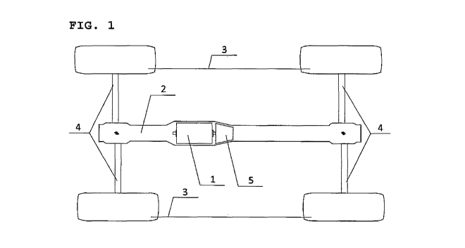
A central load - carrying tube provided inside with the integrated
rotary electric motor is described in more detail on a specific
example using the attached figures, where Fig. 1 is a schematic
drawing of a central load - carrying tube with an integrated
single rotating electric motor, Fig. 2 is a schematic drawing of
central load - carrying tube with two integrated rotary electric
motors, and Fig. 3 is a schematic drawing of central load -
carrying tube with one integrated rotary electric motor, where the
tube is attached to several axles.
2

CA 02991945 2018-01-10
W020171008770 PCUCZ2016/000035
Examples of Embodiment of the Invention
Device according to Fig. 1 and 2 comprises a central load -
carrying tube 2 fitted with two axles 4 with wheels 3, inside
which are placed two rotary electric motors 1, between which a
clutch 6 is placed, wherein transmissions / axle drives 5 are
attached on the outer side of the rotary electric motors 1. The
transmission / axle drive 5 and clutch 6 are not critical to the
subject invention and need not to be placed in a central load -
carrying tube. Conversely, the central load - carrying tube may
contain more rotary electrical motors and / or other traction
components, particularly transmissions / axle drives 5, clutches
6, differentials and downward gearings.
Device according to Fig. 3 consists of a central load - carrying
tube 2 fitted with three axles 4 with wheels 3, wherein the rotary
electric motor 1 is located inside the central load - carrying
tube 2 between the second and third axle 4 with wheels 3. The
number of rotary electric motors 1 placed inside the central load
- carrying tube may vary, as well as the rotary electric motor 1
may be supplemented by additional traction components.
Industrial Applicability
The central load - carrying tube with rotary electric motor
integrated inside is intended for road, commercial and military
vehicles. In general, this principle of central load - carrying
tube is also usable in other kinds of vehicles, assuming of course
that it is adapted to the respective type of vehicle.
3

CA 02991945 2018-01-10
WO 2017/008770
PCT/CZ2016/000035
List of reference marks
1 - Rotary electric motor
2 - Central load - carrying tube
3 - Wheel
4 - Axle
- Transmission / Axle drive
6 - Clutch
7 - Differential / Axle drive
6

Representative Drawing
A single figure which represents the drawing illustrating the invention.
Administrative Status

For a clearer understanding of the status of the application/patent presented on this page, the site Disclaimer , as well as the definitions for Patent , Administrative Status , Maintenance Fee  and Payment History  should be consulted.

Administrative Status

Title Date
Forecasted Issue Date Unavailable
(86) PCT Filing Date 2016-04-04
(87) PCT Publication Date 2017-01-19
(85) National Entry 2018-01-10
Examination Requested 2021-03-31

Abandonment History

Abandonment Date Reason Reinstatement Date
2022-10-11 R86(2) - Failure to Respond 2023-10-06

Maintenance Fee

Last Payment of $100.00 was received on 2024-03-28


 Upcoming maintenance fee amounts

Description Date Amount
Next Payment if small entity fee 2025-04-04 $100.00
Next Payment if standard fee 2025-04-04 $277.00

Note : If the full payment has not been received on or before the date indicated, a further fee may be required which may be one of the following

  • the reinstatement fee;
  • the late payment fee; or
  • additional fee to reverse deemed expiry.

Patent fees are adjusted on the 1st of January every year. The amounts above are the current amounts if received by December 31 of the current year.
Please refer to the CIPO Patent Fees web page to see all current fee amounts.

Payment History

Fee Type Anniversary Year Due Date Amount Paid Paid Date
Application Fee $200.00 2018-01-10
Maintenance Fee - Application - New Act 2 2018-04-04 $50.00 2018-03-28
Maintenance Fee - Application - New Act 3 2019-04-04 $50.00 2019-04-04
Maintenance Fee - Application - New Act 4 2020-04-06 $50.00 2020-04-06
Maintenance Fee - Application - New Act 5 2021-04-06 $100.00 2021-03-30
Request for Examination 2021-04-06 $408.00 2021-03-31
Maintenance Fee - Application - New Act 6 2022-04-04 $100.00 2022-04-01
Maintenance Fee - Application - New Act 7 2023-04-04 $100.00 2023-04-03
Reinstatement - failure to respond to examiners report 2023-10-11 $210.51 2023-10-06
Maintenance Fee - Application - New Act 8 2024-04-04 $100.00 2024-03-28
Owners on Record

Note: Records showing the ownership history in alphabetical order.

Current Owners on Record
GI4 S.R.O.
Past Owners on Record
None
Past Owners that do not appear in the "Owners on Record" listing will appear in other documentation within the application.
Documents

To view selected files, please enter reCAPTCHA code :


To view images, click a link in the Document Description column. To download the documents, select one or more checkboxes in the first column and then click the "Download Selected in PDF format (Zip Archive)" or the "Download Selected as Single PDF" button.

List of published and non-published patent-specific documents on the CPD .

If you have any difficulty accessing content, you can call the Client Service Centre at 1-866-997-1936 or send them an e-mail at CIPO Client Service Centre.


Document
Description 
Date
(yyyy-mm-dd) 
Number of pages   Size of Image (KB) 
Request for Examination 2021-03-31 5 237
Examiner Requisition 2022-06-10 4 206
Abstract 2018-01-10 1 61
Claims 2018-01-10 2 58
Drawings 2018-01-10 2 21
Description 2018-01-10 4 112
Representative Drawing 2018-01-10 1 5
International Search Report 2018-01-10 3 75
Amendment - Claims 2018-01-10 2 51
Declaration 2018-01-10 3 124
National Entry Request 2018-01-10 3 86
Cover Page 2018-03-14 1 40
Maintenance Fee Payment 2018-03-28 1 33
Maintenance Fee Payment 2019-04-04 1 33
Office Letter 2019-09-19 2 37
Maintenance Fee Payment 2024-03-28 1 33
Reinstatement / Amendment 2023-10-06 12 414
Claims 2023-10-06 2 92