Note: Descriptions are shown in the official language in which they were submitted.
MODULAR LIGHTING SYSTEM USING HANGERS AND POWER BARS
BACKGROUND OF THE INVENTION
A. Field of Invention
This invention pertains to a modular system having components that can be
assembled to form multi-level lights of various sizes, shapes and
configurations. The main
elements are canopies supporting the system, hangers, power bars, and
pendants, preferably
including light engines driving LED bulbs.
B. Description of the Prior Art
Designing lighting for a space has always been an interesting challenge
because
the lighting equipment has to meet utilitarian, technical and esthetic needs.
Thus, any such
endeavor is successful only if combining technical, architectural and artistic
skills.
Several different types of ceiling lights are presently available, including
surface
mounted lights, recessed lights and hanging lights disposed on tracks either
attached to the
ceiling or suspended below the ceiling. The first two light categories are
very conventional and
are disadvantageous because the positions of the lights are fixed and the
configurations
available for each light is very limited. Conventional track lighting provides
a little more flexibility
especially as far as the positions of the lights are concerned. However,
because of power
requirements and other factors, the number, size and shape of light fixtures
that can be used in
such systems is fairly limited.
In some instances it is advantageous to have a plurality of pendants grouped
together
for esthetic purposes and/or to provide more light for a particular space.
However conventional
track systems could accommodate such clusters only if they were factory
assembled. It would
1
CA 2991974 2019-05-27
be very helpful to have a support for a light cluster that could accommodate
several pendants
and that could be assembled in the field.
SUMMARY OF THE INVENTION
Briefly, a modular lighting system for providing light in a space includes
canopies
connectable to a power source; a plurality of horizontal bars; a plurality of
hangers, including a
first set of hangers supporting bars from said canopy and a second set of
hangers, each said
hangers including a first end disposed between and engaging said bar segment.
The system
further includes a plurality of pendants supported by the second set of
hangers from the bars.
The hangers and bars cooperate to provide electric power to said pendants from
said canopy.
Preferably, each bar includes two bar segments facing each other and being
made of a non-conductive material. Conductive rails are provided on the inner
surface of each
bar segment. The hangers include a base configured to form an interference fit
with the bar
segments. In one embodiment, the hangers are made of conductive rods or cables
that are in
electrical contact with the rails through the respective bases.
In one embodiment, the bars are straight or linear. In another embodiment, the
bars are circular or have some other curvilinear shape.
The bars preferably extend horizontally, however different bars are disposed
at
different heights and are supported from one or more canopies or straight from
a ceiling by
hangers of various configurations or cables.
Preferably, at least one of the canopies is connected to a line voltage and
transformer is used to step down the line voltage to a lower voltage such as
24 vac which is
then distributed to the pendants through the hangers and bars.
The pendants include light emitting elements such as LEDs, electronic
circuitry
for driving the LEDs, and are preferably shaped for heat dissipation. Since
the LEDs have a
long life, they are not replaceable but instead the whole pendant is replaced
as needed.
2
CA 2991974 2019-05-27
These various elements are combined in many different ways resulting in a
virtually infinite number of configurations. One class of configuration may
include several bars
disposed in a vertical plane. In another class of configurations, several bars
extend at different
angles in one plane, and are joined at a common point. Another class of
configurations may
include a combination of the first to classes. Another class of configurations
may include
several bars disposed at different heights or tiers, some bars being
perpendicular to other bars.
In one embodiment, a support arrangement for a modular lighting system
hanging from a structural element and having light generating pendants, is
provided, the said
support arrangement including a first and a second horizontal bar, each
horizontal bar including
a first and a second bar segments extending equidistant from each other to
define a vertical
space, said vertical space having identical top and bottom openings. Also
provided are a first
plurality of hangers supporting said second bar from said first bar, each said
hangers including a
first end engaging the bar segments of said first bar, a second end engaging
the bar segments
of said second bar and first and second rods extending vertically between and
being attached to
said first and second ends. Each end includes a base portion, a first outer
wall, a central wall
and a second outer wall, said walls extending perpendicularly from said base
and defining a first
slot for receiving the respective first bar segments and a second slot for
receiving the respective
second bar segments when the respective end engages one of said bars. The
central wall
extends into the respective space from said top or bottom opening.
In one embodiment, the bars are parallel to each other and the rods extend
between respective outer walls of said ends.
In one embodiment the bars are perpendicular to each other and the rods extend
between the outer walls of one end and the central wall of the other end.
In one embodiment the ends form an interference fit with the respective bars.
In one embodiment, the space is formed between inner walls of said bar
segments, said inner walls forming respective metallic channels extending
horizontally along the
3
CA 2991974 2019-05-27
length of said segments. The ends include metallic clips snapping into said
channels and
creating an electrical contact with said channel while forming an interference
fit between the
respective hanger and bar.
Preferably at least hanger is provided with a top portion for engaging a bar
and two
vertical rods having spade shaped ends that cooperate with structures in a
pendant to allow a
strong positive interlock with the pendant. The rod ends are first inserted
into holes in the
pendant and then twisted around a vertical axis. This action causes the rod
ends to twist as
well and enter a respective gap in the pendant. Once the ends enter into the
pendant past the
gap, the hanger is released to its normal position causing the rods to twist
back to their normal
position. In this position, the rod ends are trapped within the pendant
thereby providing
interlocking support for the pendant. The pendant can be removed by reversing
the operation.
The canopies include a cup-shaped body adapted for attachment to a ceiling.
Ferules
are provided that pass through the cup wall and engage the ends of hangers to
provide both
support and electrical connections thereto. Some hangers are used only for
support and,
accordingly, no electrical connection is provided.
BRIEF DESCRIPTION OF THE DRAWINGS
Fig. 1 shows an isometric view a modular lighting system constructed in
accordance with
this invention with two parallel bars suspended from a single canopy;
Fig. 2 shows an isometric view of another embodiment with bars disposed at an
angle
with each other in a single tier and suspended from a single canopy;
Fig. 3 shows an isometric view of another embodiment of the invention in which
six bars
disposed at various tiers and angles are suspended from a single canopy;
Fig. 4 shows an isometric view of another embodiment of the invention in which
several
different bars are disposed at right angle and are supported by a canopy and
other ceiling
supports;
4
CA 2991974 2019-05-27
Fig. 5 shows an isometric view another embodiment of the invention in which
two
circular bars are disposed at different tiers and supported by a single
canopy;
Fig. 6 shows another embodiment of the invention in which a single bar
disposed at a
right angle with respect to wall and supported by a wall-mounted canopy;
Figs. 7A-7K show an isometric and a cross-sectional view of a bar used in the
embodiments of Figs. 1-6;
Fig. 7L shows an isometric view of a connector used to connect three bars in
the
embodiments of Figs. 2 and 3;
Figs. 8A-8E show details of a canopy used in the embodiments of Figs. 1-6;
Figs. 9A-9J show details of a bar hanger used for interconnecting two bars in
the
embodiments of Figs. 1-6;
Fig. 10 shows a front view of a hanger used for connecting a bar to a pendant
or a
canopy in the embodiments of Figs. 1-6;
Fig. 11 shows an isometric view of a hanger with a single rod for the
embodiment of Fig.
4;
Figs. 12A-12C show views of a non-conductive hanger with a single rod for the
embodiment of Fig. 4;
Figs. 13A-13C show a top, front and isometric view of a pendant cluster used
in the
embodiment of Fig.1; and
Figs. 14A-14P show details of a bayonet-type hanger and a pendant that is
mounted
using a twisting of the hanger and is used in the embodiment of Fig. 1.
DETAILED DESCRIPTION OF THE INVENTION
The present invention pertains to a modular lighting system having a plurality
of
interchangeable elements that can be combined in many different ways to obtain
a large variety
CA 2991974 2019-05-27
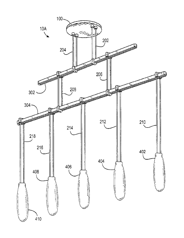
of configurations. Figs. 1-6 show four such systems identified respectively as
10A, 10B, 10C,
10D, 10E and 10F. Generally speaking, each system includes one or more
canopies 100, a
plurality of hangers 202, 204, 206, 208, 210, 212, 214, 216, 218, a plurality
of power bars 302,
304 and a plurality of pendants 402, 404, 406, 408, 410. In addition, some
systems may also
include optional connectors 500 (not shown). Unless otherwise noted, all the
hangers and all
power bars consist of two elements that have dual functions, they support the
pendants 402,
404, 406, 408, 410 and they provide power to the pendants, with one elements
forming the
positive or hot power connection and the other element defining the negative
or ground power
connection.
For example, in Fig. 1, system 10A includes a canopy 100 that supports the
system from
a ceiling or other similar architectural member in a conventional manner. In
this case, the
canopy also provides power to the system. Canopy 100 includes a conventional
power supply
connected to standard AC lines for providing power to the LED tubes in the
pendants as
discussed below. The power supply is hidden within the canopy.
Two hangers 202, 204 extend downwardly from the canopy. In one embodiment,
each
hanger discussed hereinafter consists of two solid bars or rods. These hangers
are termed the
power feed hangers. In an alternate embodiment the hangers are replaced by
multi-strand
twisted cables. As explained above, each hanger is formed of two elements
(e.g., rods or
cables). Preferably only two of the four elements (e.g., the rods of hanger
202) carry power and
the other two elements are used for support.
The hangers 202, 204 are used to support a power bar 302. Two hangers 206, 208
are
used to support a second power bar 304 and are termed bar hangers.
Another set of hangers 210-218 are used to support a plurality of pendants 402-
410.
These hangers are termed pendant hangers. The pendants 402-410 preferably
include LED.
Included in canopy 100 is a transformer steps down the line voltage from a
standard
power line to 24 VAC for the pendants 402-410. The other hanger 204 may be
6
CA 2991974 2019-05-27
electrically floating. The power from the hanger 202 flows through the bar
segments of bar 302,
hanger 206, bar 304 and hangers 210-212 to the pendants. Thus, in this
embodiment, only
some of the pendants carry power but all the power bars do.
Fig. 2 shows a system 10B in which three bars 306 are connected at a common
connector 308 that keeps the bars at a specific angle with respect to each
other to form a Y-
shaped arrangement. This angle could be 1200, 450, 135 , etc. and the bars may
but need not
be disposed at a constant angle between each other. Bars 306 are supported by
respective
hangers 202, 204, 206 from the canopy 102 as shown. The pendants and hangers
supporting
them have been omitted in this figure for the sake of simplicity.
Fig. 3 shows a system 10C with pendants arranged at several levels and
extending in
different directions from a central point below the canopy 102. This is
achieved by starting with
a Y-shaped bar arrangement of Fig. 2 formed again of three bars 306 supported
by hangers
202, 204, 206 and joined by a connector 308. However, in this case, each bar
306 is used to
support another bar 310, each bar 310 being supported by a pair of hangers
208, 210. Hanging
from each bar 310 are a plurality of pendants 410 supported by hangers 212.
All of pendants
410 supported by the same bar 310 can be disposed at different height, or
different hangers
may be disposed at different heights.
Fig. 4 shows yet another system 10D. This system 10D includes a canopy 104
with a
transformer 106. Attached to the canopy 104 is a first bar 302A using two
hangers 214. As
opposed to the hangers discussed previously, hangers 214 have a single
extended element,
such as bar, as described in more detail later. Each of the hangers 214
provides power to one
of the elements of bar 302A. However because the bar 302A is not centered
below the canopy
104 but extends in one direction away therefrom, another hanger 216, which may
be referred to
as a ceiling hanger, is used to support a distal end 314 of bar 302A. At its
top, hanger 216 is
attached to a sleeve 106 secured to the ceiling in a conventional manner.
7
CA 2991974 2019-05-27
Hangers 218 are used to attach respective pendants 402 from bar 302A. Another
hanger 220 is used to support a cluster of pendants 410.
A second bar 304A is also provided. This bar 304A is supported at one end by a
hanger
222 from bar 302A. This hanger 222 also provides power to bar 304A. A third
bar 306 is also
provided that is supported from the ceiling by ceiling hangers 216 (only one
such ceiling hanger
is being shown for the sake of clarity). Bar 306A supports the second end of
bar 304A and
receives power from said bar 304A through hanger 224. Each of the bars 302A,
304A, 306A
can be used to hang pendants of various sizes and shapes and arranged in
different
configurations as desired.
Fig. 5 shows another system 10E having a canopy 100E supporting two ring-
shaped,
rather than rectilinear bars 330, 332 arranged at two levels and with various
shapes and types
of pendants 420 extending downwardly from the respective bars 330, 332, each
being
supported and powered by a respective hanger 221. Since the diameters of the
ring-shaped
bars 330, 332 are larger than the diameter of the canopy 100E, rods or cables
221.
Fig. 6 shows a wall-mounted system 1OF with a wall mounted canopy 412. A
horizontal
bar 321 attached directly to and extending away from the canopy 412 provides
power and
supports a pendant 402 via a hanger 221. Alternately, other horizontal bars
may be supported
from bar 321 for hanging various pendants (not shown).
Details of a generic bar 300 are shown in Figs. 7A -7K. Unless otherwise
noted, all the
bars discussed here have the same configuration. In Figs. 7A-7K, bar 300 is
shown as being
straight however, the bar can be circular ellipsoid or can have other
geometric shape. The bar
300 includes two identical longitudinal segments354, 356 facing each other. A
cross- sectional
view of the bar 300 is seen in Fig. 7E. Each segment 354, 356 includes a C-
shaped main body
355 made of a non-conductive material, such as a plastic material that is
light weight but strong
so that it can support various pendants, other bars, etc. Imbedded in this
main body 355 is a
channel 360 made of a light weight conductive material such as aluminum.
Preferably each
8
CA 2991974 2019-05-27
segment 354, 356 includes a rectangular channel 360. The two segments 354, 356
are joined
together at the two ends by end connectors 362. The connectors 362 are
attached to the bars
by conventional means, such as screws 364, by an adhesive or other means.
Preferably, the two segments 354, 356 have inner surfaces spaced at a nominal
distance d throughout the length of the bar 300. The bar 300 is made in
standard lengths
ranging from to 12 to 48 inches. For very long bars, for example in excess of
24 inches, a
spacer 366 is placed between the segments. The spacer 366 may be held in place
by screws
or other means.
Fig. 7L shows details of a connector 308 used to connect three bars, for
example for the
systems of Figs. 2 and 3. The connector 308 is formed of three arms 372
disposed at an angle
of 120 degrees. The inner surfaces of the arms 372 are provided with rails 374
having the size
and shape to fit into the channels of the rails of bars 300. Three bars having
the same or
different length are attached telescopically to the connector 308.
Details of a typical canopy 100 are shown in Figs. 8A-8C. Each canopy 100
includes a
cup-shaped housing 120 that can be cylindrical, square, rectangular, etc. The
housing 120
holds a transformer 122 receiving power from line wires 124 and outputting
power at a lower
voltage on output wires 126. The output wires 126 are connected to a terminal
strip 127 used to
distribute the low ac voltage power through a plurality of lines 129. As will
be discussed in more
detail below, preferably transformer 122 outputs power at about 24 vac. On its
bottom surface
128, the housing 120 is provided with a plurality of ferrules 130. Depending
on the exact
required configuration, these ferrules 130 may be arranged single or in pairs,
and a canopy may
be provided with two four, six, eight ferrules, etc. Some of the ferrules
provide power to the
respective hangers or cables and also provide structural support. Other
ferrules do not provide
power but merely provide structural support.
9
CA 2991974 2019-05-27
As shown in Figs. 8C and 8E, each conducting ferrule 130 terminates in a
threaded bolt
132. An eyelet 134 is attached to each bolt 132 using a threaded nut 133 or
other conventional
means. Each eyelet is connected to one of the output wires 129.
As seen in Figs. 8C, 80 and 8E, each ferule 130 further includes cylindrical
sleeve 140
with a ferule body 147 attached to bolt 132 and extending through the housing
120 and below
surface 128. The sleeve 140 is electrically insulated from the housing 120 and
receives the
conductive end of a rod 142 forming a part of a hanger as described below or a
cable. A set
screw 144 is used to secure the rod 142 in the sleeve 140. A washer 139 is
disposed below nut
133 and is insulated from the housing 120 by an insulating disc 143. A second
insulating disc
145 is disposed above the ferule body 147 to insulate it from the housing 120
as well. The rod
142 is preferably covered with an insulator 149.
The non-conductive ferrules have a similar configuration but are not connected
to any
output wires 126. The ferrules receive rods similar to rod 142 but these
latter rods do not
provide power.
There are several different types of bar hangers are provided: hangers for
supporting
bars from canopies, hangers for supporting bars from ceilings (without a power
connection),
hangers for supporting one bar from another bar and hangers for supporting
pendants. All
these hangers have must be able to interface with a bar at least at one end as
described below.
There are two types of bar-to-bar hangers: parallel hangers for connecting two
parallel
bars and perpendicular hangers connecting two bars running perpendicular two
each other.
Figs. 9A-9G show details of parallel bar hanger such as hanger 206 supporting
bar 304
from bar 302 in Fig. 1. The hanger 206 includes two vertical segments 230A,
230B. At the top
and the bottom, the two segments 230A, 230B have their ends imbedded in
identical W-shaped
bases 232, shown in more detail in Figs. 9B-9E. The base 232 forms two
channels 234,
CA 2991974 2019-05-27
236 with a wall 238 separating the two channels. The base 232 is further
formed with two
metallic springs or clips 240, 242. Clip 240 is electrically attached to
segment 230A within the
base 232, and clip 242 is connected to segment 230B. Preferably, base 232 is
made of a non-
conductive material and is overmolded to cover portions of the clips 240, 242
and segments
230A, 230B. In one
embodiment, the two bases 232 have a single, unitary structure. In
another embodiment, at least the top base is made of two sections 232A, 232B
that snap
together along line 232 forming an interference fit therebetween.
As can be seen in Figs. 9F and 9G, the bases 232 as sized and shaped so that
they fit
over and engage the bars 302, 304. Importantly, the clips 240, 242 are sized
and shaped so
that they engage the rails 356, 358. The clips 240, 242 have a flat section
244 sized and
shaped to snap into the channels 356, 358 of the bars 302, 304. In this manner
not only do the
clips 240, 242 provide a solid electrical contact with the rails 356, 358 but
they also stabilize the
hangers on the bars and ensure that the lower bar 304 remains stiff and moves
around in use.
The clips may be made from beryllium copper.
Hanger 208 has a similar configuration however the clips need not be connected
electrically to the hanger segments. In other cases, for example, in the
configuration shown in
Fig. 4, hangers 222 do provide electrical connection to bars 304A and 306A.
The hanger segments 230A, 230B are provided in various lengths as required to
obtain
the various systems described above, and they are preferably made in the shape
of rods of a
stiff but somewhat springy material having shape memory such as a
phosphor/bronze alloy.
Preferably except where an electrical contact is required, the rods are
covered or painted with a
thin electrically insulating material.
The hangers can be installed by separating the two segments 230A, 230B,
passing the
ends of the respective bars 302, 304 between the segments, then lowering or
raising the bars
toward the respective bases 232 and then snapping the bases onto the bars into
the
configurations shown in Figs. 9F and 9G.
11
CA 2991974 2019-05-27
As discussed above, and illustrated in more detail below, in some instances,
the power
bars extend perpendicularly to each other. For example, in Fig. 4, bars 302
and 304 are
perpendicular to each other. These bars are interconnected using a hanger 222
shown in Figs.
9H-9J. This hanger 222 has two segments 272A, 2728 and a base 232 similar to
the base 232
in Figs. 9A-9G. However, at the bottom hanger 222 is provided with a different
base 274. This
base 274 is formed with two side wings 274A, 274B and a center wall 274C.
Clips 276, 278 are
provided on the center wall 274C and are connected electrically with segments
272A, 272B,
respectively as show in Fig. 9J. The center wall 274C is made with two holes
280A, 280B with
the lower ends of segments 272A, 272B extending into the holes and being
secured to the base
222. The base 270 is sized and shaped to engage and support the power bar
segments 304A,
304B of a bar 304A with the segments 272A, 272B providing power to these power
bar
segments. The base 232 engages the segments of the bar 302A in the manner
discussed
above.
In addition to the bar hangers, other types of hangers are used in the system
as well.
Fig. 10 shows a side view of a hanger having a base 232 and two segments 252A,
252B. The
difference between this hanger and the hanger in Figs. 9A is that the ends of
segments 252A,
252B are straight bare ends of the conductive rods. This bare ends are then
inserted into the
ferrules 130 as shown in Fig. 80. (Of course, for this use, the hanger is
turned upside down).
Alternatively, the hanger is used a pendant cluster such as cluster 410 in
Fig.4 or other
pendants.
Fig. 11 shows a single rod hanger 214. This hanger 214 includes a base 274A
similar to
base 274 shown in Figs. 9H, 9J. The base 274A has two clips 276, 278. When the
base 274 is
mounted on a bar (such as bar 302A), the clips 276, 278 engage the rail within
the bar 302A as
discussed above. However, only one of the clips (say clip 276) is connected to
rod 272C. The
free end 2720 of the rod 272C is attached to the ferrule of a canopy. Two such
hangers 214 are
12
CA 2991974 2019-05-27
used to support bar 302A (as seen in Fig. 4), with each of the hangers feeding
power to one of
the rails of the bar.
Fig. 12A-12C show a nonconductive hanger 216 used for supporting a bar, such
as bar
304A in Fig. 4 from a ceiling. This hanger 216 provides only support and
therefore it can have
an elongated member 272D which may but need not be identical to the rod 272C
in Fig. 11.
The member 272D ends in a base 274B that is similar to the base 274 but need
not have any
clips since there is no need to connect to the rails of the bar304A. Since
there are no clips
provided for the base 274B, a cover 274C is attached to the body 274D of the
base 274B to
insure that the bar does not slip out. The cover 274C is attached to the body
274D by screws
274E or other conventional means. The other end of the elongated member 272D
is attached
to a sleeve 277 via a set screw 277A. Preferably, the ferrule 277 is similar
to the ferrules of the
canopy 100 in that it has a similar sleeve for capturing the end of the member
272D. A small
screw (not shown) is used as an attachment means. A large screw 279 or other
conventional
means may be used to attach the sleeve 277 directly to the ceiling or other
architectural surface.
Alternatively, the screw 279 is attached to a mounting post 281 and an anchor
283 (Fig. 12C).
Figs. 13A-13C show a top, plan and isometric view of lamp cluster 410. The
cluster 410
includes a distributor 430, and three pairs of connectors 432 connecting the
distributor 430 to
three pendants 402A, 402B, 4020. The pendants can have the same or different
shapes.
Importantly, the distributor has to top holes 434, 436. The ends of the rods
shown in Fig. 9 are
inserted into the holes 434, 436 and then set screws on the sides of the
distributor, such as at
438 are tightened thereby attaching and mechanically securing the pendant
cluster 410 to the
hanger. The hanger and the cluster can now be hanged from a bar 300.
Other structures may be used for attaching pendants to the hangers. One such
structure is shown in Figs. 14A-140. Fig. 14A shows an orthogonal view of
hanger 210 being
inserted into pendant 402. As shown in Figs. 14A, 14B 140 and 14D, the hanger
210 includes
two vertical segments 602A, 602B joined by standard base 232. The segment 602A
is
13
CA 2991974 2019-05-27
terminated at the bottom with a connecting spade 604 that has a generally
flat, rectangular
cross section (as seen in Fig, 14D) of thickness t1. Spade 604 includes a
narrow shank 606
having a height h1 and a generally square tip having a width w1. Segment 602B
has the same
shape as segment 602A and the two spades 604 are normally aligned in parallel
to each other
and perpendicular to the plane formed by the two parallel segments 602A, 6026,
as seen in Fig.
14A.
Pendant 410 is formed with an upper and a lower section 610, 612 (see Fig.
14L). The
upper section 610 contains a light engine (not shown) that is powered by the
24 vac source
provided by the segments 602A, 602B and generates appropriate power to light
generators
(such as LEDs -not shown) disposed in the lower section 612. The walls of the
lower section
are translucent or transparent to allow the light from the light sources to be
projected outwardly
and provide space illumination. Various pendants may have sections of
different shapes and
sizes. In one embodiment, the upper section 610 includes a cavity 620 with two
holes 622, 624.
The cavity 620 holds two contacts 630, 640 (see Figs. 14E, 14F). Each contact
is
connected to the light engine (not shown). Contact 630 is formed with two
facing blades having
flat portions 632, 634. The distance between the blade portions 632, 634 is t2
which is
preferably equal or slightly larger than t1 but smaller than w. Contact
640 has two similar
blades with flat portions 642, 644. The blade portions 632, 634, 642, 644 have
a height h2 that
is slightly smaller than height h1.
The pendant 410 is attached to the hanger 210 as follows. First, the hanger
210 is
positioned on top of pendant 410 with the tips of spades 604 inserted into
holes 622, 624 as
seen in Fig, 14A, 14G. In this orientation, the spades 604 come into contact
with the top pf
respective blades 630, 640, as shown in Fig, 14H and stop because they can go
no further.
Next, the pendant 610 and top of the hanger 210 is rotated in direction A by a
quarter
turn (90 degrees). This rotation causes the spades 604 to turn by the same
angle so that they
are now in parallel with the blade sections 632, 634, or 642,644 respectively,
as seen in Figs.
14
CA 2991974 2019-05-27
141 and 14J. At this point, the hanger 210 can be and is pushed further
downward so that the
spades 604 enter into cavity 620 between the blades. This motion downward can
continue until
the tips 608 pass the blade sections 632, 634, 642, 644 (Fig. 14K).
Now the hanger 210 is released and the spring action of the two segments 602A,
602B
cause the top of the hanger 210 to rotate back in direction B (Fig. 14L)
toward its natural or rest
configuration. This action causes the spades 604 to rotate as well. As this
action is completed,
the tips 608 become trapped under the blade sections (see Figs. 14M-140). In
this manner the
hanger 210 and pendant 410 become interlocked. The hanger 210 and pendant 410
can be
attached to any bar 300 as required. If necessary, the pendant 410 can be
separated from the
hanger 210 by twisting it by a quarter turn and reversing the sequence
discussed above.
As discussed above and illustrated in the drawings, the various components or
elements
described above can be combined into numerous different kinds of
configurations. The figures
show some systems that include several subsystems that are attached so that
they can be
extend in three dimensions, to create a linear or circular configurations, or
combinations thereof.
Moreover, while the systems discussed above are all suspended from a ceiling,
other systems
are shown and described (together with any special components, if any) that
are attached to
vertical walls¨e.g. sconce-type systems.
Electrically, all these systems have one or more canopies, bars, and hangers
that
provide a power supply for the canopies. As discussed above, preferably power
within the
system is distributed at 24 vac to the individual pendants. Light engines
within the pendants the
use this source to generate light via LEDs or other similar efficient, long
life light elements. The
systems do not use any conventional bulbs that need replacement. It is
presently estimated
that the linear distance between a canopy and the furthest pendant can be up
to about 30 feet.
For larger systems, it is advisable to use two or more canopies. As indicated
above, for two or
more source-systems, the bars can be interconnected mechanically but isolated
electrically as
needed. As discussed above, in conjunction with Fig. 3, one bar of a system,
for example bar
CA 2991974 2019-05-27
306 can have two sections 306A, 306B that are electrically insulated from each
other with the
rails of each section being fed and electrically connected to a different
canopy 100.
In this manner, the modular presented herein can be used to make systems
having
different configurations. Because the hangers can be attached easily in the
field to the
canopies, the bars and the pendants, each system can be assembled very quickly
and
efficiently using the various components described above. Moreover, many
different kinds of
pendants can be used with the system. As long as each pendant is capable of
being connected
to any of the hangers described above, it can be incorporated into a system
without any
changes to any of its other components.
Obviously numerous modifications may be made to the invention without
departing from
its scope as defined in the appended claims.
16
CA 2991974 2019-05-27