Note: Descriptions are shown in the official language in which they were submitted.
CA 02992020 2018-01-09
WO 2017/020116 PCT/CA2016/050701
A PREFORM, A MOLD STACK FOR PRODUCING THE PREFORM, AND A
PREFORM HANDLING APPARATUS FOR HANDLING THE PREFORM
FIELD OF TECHNOLOGY
The present technology generally relates to, but is not limited to, molding
systems and
processes, and more specifically the present technology relates to, but is not
limited to, a
preform, a mold stack for producing the preform, and preform handling
apparatus for handling
the preform.
BACKGROUND
Molding is a process by virtue of which a molded article can be formed from
molding material
by using a molding system. Various molded articles can be formed by using the
molding
process, such as an injection molding process. One example of a molded article
that can be
formed, for example, from polyethylene terephthalate (PET) material is a
preform that is
capable of being subsequently blown into a beverage container, such as a
bottle and the like.
As an illustration, injection molding of PET material involves heating the PET
material to a
homogeneous molten state and injecting, under pressure, the so-melted PEI
material into a
molding cavity defined, at least in part, by a female cavity piece and a male
core piece mounted
respectively on a cavity plate and a core plate of a mold. The cavity plate
and the core plate are
urged together and are held together by clamp force, the clamp force being
sufficient to keep
the cavity and the core pieces together against the pressure of the injected
PET material. The
molding cavity has a shape that substantially corresponds to a final cold-
state shape of the
molded article to be molded. The so-injected PET material is then cooled to a
temperature
sufficient to enable ejection of the so-formed molded article from the mold.
When cooled, the
molded article shrinks inside of the molding cavity and, as such, when the
cavity and core
plates are urged apart, the molded article tends to remain associated with the
core piece.
Thereafter, the molded article can be ejected off of the core piece by use of
one or more
ejection structure. Ejection structures are known to assist in removing the
molded articles from
the core halves. Examples of the ejection structures include stripper plates,
stripper rings and
neck rings, ejector pins, etc.
1
CA 02992020 2018-01-09
WO 2017/020116 PCT/CA2016/050701
With reference to Figure 1, a preform 100 is depicted, the preform 100 being
an example of a
typical prior art preform. The preform 100 consists of a neck portion 102, a
base portion 106
and a body portion 104 extending between the neck portion 102 and the base
portion 106. The
base portion 106 is associated with a substantially spherical shape
(specifically, hemispherical)
that terminates in a vestige portion 108.
The preform depicted in Figure 1 is typically used for blow-molding into a
beverage container,
such as a bottle for a still or carbonated beverage. A typical final blow-
molded bottle is shown
in Figure 2 at 200, the bottle 200 being an example of a still water bottle.
Such a container can
be said to be a symmetrical container in a sense that the blown bottle 200 is
circumferentially
symmetrical around an imaginary central axis (not depicted) thereof.
There is another type of a final shaped container used in the industry,
generally known as an
"offset bottle" or an "offset neck bottle". An example of a typical offset
bottle is depicted at
210 in Figure 2. The bottle 210 is referred to as an "offset bottle" due to
the fact that the neck
of the bottle (i.e. a portion of the bottle 210 blown from the neck portion
102 of the preform
100) is offset from the imaginary central axis (not depicted) of the bottle
210. The imaginary
central axis is also sometimes referred to by those of skill in the art as a -
center of symmetry".
Typically, the neck of the bottle 210 is offset to facilitate the ease of
pouring of the liquid
contained in the bottle 210, when in use. Alternatively, the neck of the
bottle 210 can be offset
for aesthetic or "branding" purposes. For example, it is a standard practice
to offset necks of the
bottles 210 that are destined to contain liquids such as (but not limited to):
machine oil,
washing detergents, household cleaning products and the like.
In order to produce a bottle (such as the bottle 200 or the bottle 210) from
the preform 100, in a
typical two-stage production process, the preform 100 is reheated using an
infra-red (IR) or
other type of a heating element of a blow-molding or a stretch-blow-molding
machine. It is
known to apply preferential (selective) reheating to different portions of the
preform 100, when
it is desired to stretch-blow-mold portions of the preform 100 differently,
for example, when
producing the bottle 210 having an offset neck finish or, otherwise, having a
non-circular form.
It is also known to apply preferential blow-molding to portions of the preform
100 to
selectively stretch-blow-mold portions of the preform 100 to produce the
bottle 210.
The design of the preform (such as length, wall thickness, neck finish design,
support ledge
design and the like) can vary from one preform to another and depends, amongst
other things,
2
CA 02992020 2018-01-09
WO 2017/020116 PCT/CA2016/050701
on the type of the bottle to be blow molded from the preform, performance
characteristics of
the bottle to be blow molded from the preform, etc.
Examples of the various designs and features of the preforms can be found in
the following
documents:
US patent 4,311,246 discloses a synthetic resin bottle produced by blow-
molding a parison of
a synthetic resin. In the blow-molding process of the parison, the portion of
the parison
supporting the handle is prevented from being expanded, thereby to
sufficiently increase the
supporting strength of the handle. Since the bottle product has its drum
recessed in the vicinity
of the handle, the grip of the handle can be facilitated.
US patent application 2005/0037169 teaches a method and a device for producing
blow-
molded plastic hollow bodies (60). The device is of enhanced design which
avoids the
shortcomings of traditional blow-molding technology. The extrusion die
according to this
invention is adjustable for different settings to produce different, partly
overlapping wall
thicknesses of the parison blank in order to compensate for the
insufficiencies inherent in
blow-molding and to obtain a finished blow-molded product with as consistent
and uniform a
wall thickness as possible, with an overlay, for instance in vertical wall
areas, of evenly spaced
longitudinal ribs (68). A technical concept is introduced whereby, as a novel
process, the two
conventional measures used to achieve a uniform wall thickness in the finished
blow-molded
hollow body are complemented by an additional, third step which makes it
possible to produce
containers whose hollow bodies (60) are provided with targeted, intentional
and reproducible
irregular wall thickness patterns.
US patent 3,159,697 discloses Blow and compression molding eccentrically thick
parison.
US patent 3,309,443 teaches a plastic molding.
.. US patent application 2004/0108627 discloses system and method for making a
specialized
preform and for fabricating a container from the specialized preform that
includes a first
preform molding assembly in which a preliminary preform is molded so as to
have a first
sidewall portion that is thicker than the surrounding sidewall areas. A final
preform is molded
from the primary preform in a second preform molding assembly, wherein fluid
pressure is
utilized to mold the thickened first sidewall portion into a lateral
projection that corresponds
3
CA 02992020 2018-01-09
WO 2017/020116 PCT/CA2016/050701
and size in shape to a handle structure that is desired in the final
container. The specialized
final preform is then positioned within a container mold that is constructed
to pinch the lateral
projection during blowmolding of the final container so as to define an
integral molded handle
portion having a central sealed slug area that is later removed.
US patent 4,439,393 teaches a synthetic resin bottle produced by blow-molding
a parison of a
synthetic resin. In the blow-molding process of the parison, the portion of
the parison
supporting the handle is prevented from being expanded, thereby to
sufficiently increase the
supporting strength of the handle. Since the bottle product has its drum
recessed in the vicinity
of the handle, the grip of the handle can be facilitated.
to US patent 5,057,267 discloses a parison forming device for forming
hollow polymer extrudes
of variable wall thickness in either the circumferential or longitudinal
directions, or in any
combination thereof. The parison forming device consists of a die-head
assembly and mandrel
assembly, concentrically arranged, creating an annual opening. The inner or
outer
circumferential perimeter of the annular opening may be selectively modified
at specific radial
locations through radially displaceable slides positioned about the annular
opening. The slides,
attached to either the die-head assembly or mandrel assembly, may be actuated
during parison
formation via hydraulic or other methods so as to provide suitable wall
thickness profiles for
later finished polymer products.
US patent 6,355,204 teaches a dual-chamber container that is formed in an
injection blow
molding process. Two preforms are injection molded around respective core
rods. The
preforms and core rods are then moved to a blow mold, in which the preforms
are molded to
the confines of the mold. The blow mold has partial walls between the two
cavities, which
provide directional control over the preforms as the preform wall portions are
blown against
and contact welded to each other. The outer walls of the preforms, which must
travel and
stretch a greater amount than the inner walls, are formed thicker in the
preform molding
operation.
US patent 6,872,354 discloses parison for a container having a substantially
constant wall
thickness, the container having a base, a top edge defining a round opening,
the top edge
defining a plane which is not parallel to the plane of the base, a neck
portion disposed at the
same angle as the plane defined by the top edge, a front outer surface, and a
rear outer surface
having a lower portion and an upper portion. The parison comprises a
cylindrical upper neck
portion having a cavity extending therethrough, the upper nock having a top
surface edge
4
CA 02992020 2018-01-09
WO 2017/020116 PCT/CA2016/050701
defining a top plane. The parison also has a hollow, elongated body portion
having a closed
lower end and an upper end, the lower body portion having a major axis
extending in a
direction parallel to the longitudinal axis of the cylindrical upper neck
portion, and having a
front wall and a rear wall. The front wall is thicker than said rear wall.
Also included in the
invention is a method of producing a bottle from the parison.
US patent 7,357,967 teaches method of making an identifiable article such as a
container or
container preform. A molded plastic container or container preform is provided
that includes a
wall having at least one layer of matrix resin and at least one layer of
barrier resin that is
blended with an additive. The wall has at least one localized portion of
predetermined
geometry in which the barrier layer is thicker than surrounding portions of
the wall, and within
which the additive is discernable under visible or UV light so as to provide a
means to prevent
use of counterfeit containers.
US design patents 241,817; US design patents 354,916; US design patents
513,990; US
design patents 555,481 and US design patents 682,110 disclose various further
implementation for a design of the preform 100.
SUMMARY
According to a first broad aspect of the present technology, there is provided
a preform suitable
for subsequent blow-molding into a final-shaped container. The preform
comprises: a neck
portion; a base portion; and a body portion extending between the neck portion
and the base
portion; the body portion being defined between a circular inner surface and a
circular outer
surface defined along laterally offset axis along substantially the entire
length of the body
portion, such that a wall thickness varies circumferentially around the
preform.
In some embodiments of the preform, the wall thickness comprises a first point
of a plurality of
points around a circumference of the body portion and a second wall thickness
at a second
point of the plurality of points around the circumference of the body portion.
In some embodiments of the preform, the first wall thickness and the second
wall thickness are
selected based on blow-molding considerations for a respective one of the
first point and the
second point.
5
CA 02992020 2018-01-09
WO 2017/020116 PCT/CA2016/050701
In some embodiments of the preforni, one of the first wall thickness and the
second wall
thickness is selected to be larger where the respective one of the first point
and the second point
needs a longer travel distance during a blow-molding process.
In some embodiments of the preform, the base portion is defined between an
inner end surface
and an outer end surface that extend from the circular inner surface and the
circular outer
surface of the body portion, respectively, coaxially therewith, wherein a base
thickness of the
base portion varies circumferentially around the preform.
According to another broad aspect of the present technology, there is provided
a preform
suitable for subsequent blow-molding into a final-shaped container. The
preform comprises: a
neck portion; a base portion; and a body portion extending between the neck
portion and the
base portion; the body portion being defined between a circular inner surface
and a circular
outer surface, the body portion being associated with a wall thickness, the
wall thickness being
circumferentially uneven at any given cross section point along substantially
the entire length
of the body portion.
In some embodiments of the preform, the wall thickness comprises a first point
of a plurality of
points around a circumference of the body portion and a second wall thickness
at a second
point of the plurality of points around the circumference of the body portion.
In some embodiments of the preform, the first wall thickness and the second
wall thickness are
selected based on blow-molding considerations for a respective one of the
first point and the
second point.
In some embodiments of the preform, one of the first wall thickness and the
second wall
thickness is selected to be larger where the respective one of the first point
and the second point
needs a longer travel distance during a blow-molding process.
In some embodiments of the preform, the base portion is defined between an
inner end surface
and an outer end surface that extend from the circular inner surface and the
circular outer
surface of the body portion, respectively, coaxially therewith, wherein a base
thickness being
circumferentially uneven at any given cross section point along substantially
the entire length
of the base portion.
According to another broad aspect of the present technology, there is provided
a molding stack
for producing a preform, the preform being suitable for subsequent blow-
molding into a final-
shaped container, the preform having a neck portion; a base portion; and a
body portion
6
CA 02992020 2018-01-09
WO 2017/020116 PCT/CA2016/050701
extending between the neck portion and the base portion. The molding stack
comprises: a core
insert for defining an inner skin of the preform, a cavity insert for defining
an outer skin of the
body portion; a gate insert for defining a portion of an outer skin of the
base portion; and a pair
of neck rings for defining a portion of an outer skin of the neck portion, at
least one of the
core insert, the cavity insert, the gate insert and the pair of neck rings
being dimensioned for
defining the body portion of the preform, such that the body portion is
defined between a
circular inner surface and a circular outer surface defined along laterally
offset axes along
substantially the entire length of the body portion, such that a wall
thickness varies
circumferentially around the preform.
1() In some embodiments of the molding stack, the molding stack further
comprises a core lock
ring for attaching, in use, the core insert to a core plate.
In some embodiments of the molding stack, at least one of the core insert, the
cavity insert, the
gate insert and the pair of neck rings comprises the cavity insert and wherein
during production
of the cavity insert a geometry of a cavity molding surface is defined using
at least one of a
lathe operation, a milling operation and a splitting operation such that the
body portion of the
preform is defined between a circular inner surface and a circular outer
surface defined along
laterally offset axes along substantially the entire length of the body
portion, such that a wall
thickness varies circumferentially around the preform.
In some embodiments of the molding stack, at least one of the core insert, the
cavity insert, the
gate insert and the pair of neck rings comprises the gate insert and wherein
during production
of the gate insert a geometry of a base molding surface is defined using at
least one of a lathe
operation, a milling operation and a splitting operation such that the body
portion of the
preform is defined between a circular inner surface and a circular outer
surface defined along
laterally offset axes along substantially the entire length of the body
portion, such that a wall
thickness varies circumferentially around the preform.
In some embodiments of the molding stack, at least one of the core insert, the
cavity insert, the
gate insert and the pair of neck rings comprises the core insert and wherein
during production
of the core insert a geometry of a core molding surface is defined using at
least one of a lathe
operation, a turning and milling operation and a Direct Metal Laser Sintering
(DMLS)
operation such that the body portion of the preform is defined between a
circular inner surface
and a circular outer surface defined along laterally offset axes along
substantially the entire
length of the body portion, such that a wall thickness varies
circumferentially around the
preform.
7
CA 02992020 2018-01-09
WO 2017/020116 PCT/CA2016/050701
According to yet another broad aspect of the present technology, there is
provided a preform
suitable for subsequent blow-molding into a final-shaped container. The
preform comprises: a
neck portion; a base portion; and a body portion extending between the neck
portion and the
base portion; the body portion being defined between an inner surface and an
outer surface, the
body portion defining a circumferential wall thickness along substantially the
entire length of
the body portion, the circumferential wall thickness being non-uniform
circumferentially
around the preform.
In some embodiments of the preform, the base portion is defined between an
inner end surface
and an outer end surface that extend from the circular inner surface and the
circular outer
surface of the body portion, respectively, coaxially therewith, wherein a base
thickness being
circumferentially non-uniform around the preform.
According to yet another aspect of the present technology, there is provided
an injection
molding system, comprising: a mold for molding a preform having a body
portion, the body
portion of the preform having a cylindrical inner surface and a cylindrical
outer surface, the
cylindrical outer surface being offset, in an offset dimension, from the
cylindrical inner surface
such that a wall thickness of the body portion varies about a circumference of
the preform; and
a take-off device for retrieving the preform from the mold, the take-off
device being movable,
in the offset dimension, between an outboard position and an inboard prefotTn-
loading position.
In some embodiments of the injection molding system, the take-off device
comprises a preform
carrier and, when the take-off device is in the inboard preform-loading
position, the preform
carrier is aligned with whichever one of the cylindrical inner and outer
surfaces of the body
portion of the preform shall act as a contact surface during preform retrieval
by the preform
carrier.
In some embodiments of the injection molding system, the cylindrical outer
surface of the body
portion of the preform acts as the contact surface during preform retrieval by
the preform
carrier, the preform carrier is configured to retrieve the preform from a mold
core of the mold,
and the preform carrier is offset from the mold core, in the offset dimension,
when in the
inboard preform-loading position.
According to a further aspect of the present technology, there is provided a
preform handling
apparatus for retrieving a preform from a mold core half of a mold,
comprising: a take-off
device having a preform carrier; and a take-off device alignment mechanism for
maintaining
the preform carrier in alignment with a cylindrical outer surface of a body
portion of the
8
CA 02992020 2018-01-09
WO 2017/020116 PCT/CA2016/050701
preform regardless of whether the cylindrical outer surface of the body
portion of the preform
is concentric with a cylindrical inner surface of the body portion of the
preform.
In some embodiments of the preform handling apparatus, the take-off device
alignment
mechanism defines a first preform-loading position for the take-off device for
use when the
cylindrical outer surface of the body portion of the preform is concentric
with the cylindrical
inner surface of the body portion of the preform and a second preform-loading
position for the
take-off device for use when the cylindrical outer surface of the body portion
of the preform is
offset from the cylindrical inner surface of the body portion of the preform.
The take-off device
may be movable from an outboard position to either of the first and second
preform-loading
positions.
In some embodiments of the preform handling apparatus, the take-off device is
movable along
a linear trajectory in a spatial dimension and each of the first and second
preform-loading
positions is situated along the linear trajectory.
In some embodiments of the preform handling apparatus, the preform is molded
so that the
cylindrical outer surface of the body portion of the preform is offset from
the cylindrical inner
surface of the body portion of the preform in the spatial dimension in which
the take-off device
is movable.
In some embodiments of the preform handling apparatus, a distance between the
first preform-
loading position and the second preform-loading position is one-half of a
difference in wall
thickness between a thickest wall of the body portion of the preform and a
thinnest wall of the
body portion of the preform.
According to another aspect of the present technology, there is provided a
preform handling
apparatus for retrieving, from a mold half of a mold, a preform having a body
portion with a
cylindrical inner surface and a cylindrical outer surface, the preform
handling apparatus
comprising: a take-off device having a preform carrier; and a take-off device
alignment
mechanism for selectively adjusting the take-off device between: a first
preform-loading
position, relative to the mold half, for use when the cylindrical inner and
outer surfaces of the
body portion of the preform are concentric; and a second preform-loading
position, relative to
the mold half, for use when the cylindrical inner and outer surfaces of the
body portion of the
preform are non-concentric.
In some embodiments of the preform handling apparatus, the mold half is a mold
core half
comprising a mold core and: in the first preform-loading position of the take-
off device, the
9
CA 02992020 2018-01-09
WO 2017/020116 PCT/CA2016/050701
preform carrier is aligned with the mold core; and in the second preform-
loading position of the
take-off device, the preform carrier is offset from the mold core.
In some embodiments of the preform handling apparatus, the cylindrical outer
surface of the
body portion of the preform is offset, by an offset distance, from the
cylindrical inner surface of
the body portion of the preform, and the second preform-loading position is
offset from the first
preform-loading position by the same offset distance.
In some embodiments of the preform handling apparatus, the offset distance
equals one-half of
a difference in wall thickness between a thickest wall and a thinnest wall of
the body portion of
the preform when the cylindrical inner and outer surfaces of the body portion
of the preform are
to non-concentric.
In some embodiments of the preform handling apparatus, the take-off device is
movable, in a
spatial dimension, between an outboard position and the first and second
preform-loading
positions.
In some embodiments of the preform handling apparatus, the take-off device is
movable, in a
first spatial dimension, between an outboard position and either the first
preform-loading
position or the second preform-loading position, and the take-off device is
adjustable, in a
second spatial dimension orthogonal to the first spatial dimension, between
the first and second
preform-loading positions.
According to yet another aspect of the present technology, there is provided a
method of using
a take-off device having a preform carrier to retrieve a preform from a mold
half, comprising:
when cylindrical inner and outer surfaces of a body portion of the preform are
concentric,
placing the take-off device in a first preform-loading position relative to
the mold half; and
when the cylindrical inner and outer surfaces of a body portion of the preform
are non-
concentric, placing the take-off device in a second preform-loading position
relative to the
mold half, so that, regardless of which of the cylindrical inner and outer
surfaces of the body
portion of the preform shall act as a contact surface during preform retrieval
by the preform
carrier, the preform carrier shall be aligned with the contact surface of the
body portion of the
preform.
In some embodiments of the method, the placing of the take-off device in the
first or second
preform-loading position comprises moving the take-off device, from an
outboard position,
along a linear trajectory, to the first or second preform-loading position
respectively, and each
of the first and second preform-loading positions is defined along that same
linear trajectory.
CA 02992020 2018-01-09
WO 2017/020116 PCT/CA2016/050701
According to still another aspect of the present technology, there is provided
a preform
handling apparatus for retrieving a preform from a mold, comprising: a take-
off device having
a preform carrier; and a take-off device alignment mechanism for maintaining
the preform
carrier in alignment with a contact surface of a body portion of the preform
regardless of any
offset between a longitudinal axis of a cylindrical outer surface of the body
portion of the
preform and a longitudinal axis of a cylindrical inner surface of the body
portion of the
preform.
These and other aspects and features will now become apparent to those skilled
in the art
upon review of the following description of specific non-limiting embodiments
in conjunction
with the accompanying drawings.
DESCRIPTION OF THE DRAWINGS
A better understanding of the non-limiting embodiments of the present
technology (including
alternatives and/or variations thereof) may be obtained with reference to the
detailed
description of the non-limiting embodiments along with the following drawings,
in which:
Figure 1 depicts a cross section view of a preform implemented in accordance
with known
techniques.
Figure 2 is a schematic representation of two final-shaped blow-molded
containers, both
implemented in accordance with the known techniques.
Figure 3 is a side view of a preform implemented in accordance with non-
limiting
embodiments of the present technology.
Figure 4 is a section view of the preform of Figure 3, section taken along
lines 4-4.
Figure 5 is an exploded view of a molding stack that can be used for producing
the preform of
Figure 3.
Figure 6 is a schematic depiction of an injection molding system;
Figures 7 and 8 are transverse cross-sectional views of a preform carrier in
the molding system
of Figure 6 during retrieval of a preform;
11
H-8055-1-WO
Figure 9 is a schematic depiction of an alternative injection molding system;
Figure 10 schematically depicts movement of a take-off device of the system of
Figure 9;
Figure 11 is a transverse cross-sectional view of a preform carrier in the
molding system of Figure
9 during retrieval of a first type of preform;
Figure 12 schematically depicts movement of a take-off device of the system of
Figure 9; and
Figure 13 is a transverse cross-sectional view of a preform carrier in the
molding system of Figure
9 during retrieval of a second type of preform.
DETAILED DESCRIPTION OF EMBODIMENTS
Reference will now be made in detail to various non-limiting implementations
for producing a
preform. It should be understood that other non-limiting implementations,
modifications and
equivalents will be evident to one of ordinary skill in the art in view of the
non-limiting
implementations disclosed herein and that these variants should be considered
to be within the
scope of the present disclosure. Furthermore, it will be recognized by one of
ordinary skill in the
art that certain structural and operational details of the non-limiting
implementations discussed
hereafter may be modified or omitted (i.e. non-essential) altogether. In other
instances, well
known methods, procedures, and components have not been described in detail.
It is to be further expressly understood that the injection mold and its
components, as well as
specific implementation details of the preform, are depicted merely as an
illustrative
implementation of the present technology. Thus, the description thereof that
follows is intended
to be only a description of illustrative examples of the present technology.
This description is not
intended to define the scope or set forth the bounds of the present
technology. In some cases,
.. what are believed to be helpful examples of modifications to the injection
mold and/or its
components may also be set forth below. This is done merely as an aid to
understanding, and,
again, not to define the scope or set forth the bounds of the present
technology. These
modifications are not an exhaustive list, and, as a person skilled in the art
would understand,
other modifications are likely possible. Further, where this has not been done
(i.e. where no
examples of modifications have been set forth), it should not be interpreted
that no modifications
are possible and/or that what is described is the sole manner of implementing
that element of the
present technology. As a person skilled in the art would understand, this is
likely
12
Date Recue/Date Received 2021-05-06
CA 02992020 2018-01-09
WO 2017/020116 PCT/CA2016/050701
not the case. In addition it is to be understood that the injection mold
and/or its components
may provide in certain instances simple implementations of the present
technology, and that
where such is the case they have been presented in this manner as an aid to
understanding. As
persons skilled in the art would understand, various implementations of the
present technology
.. may be of a greater complexity. Furthermore, where specific details of the
different
implementations are presented with reference to discrete implementations, a
person skilled in
the art is expected to combine specific implementational details of one
discrete implementation
with specific implementational details of another discrete implementation,
even though such a
combination may not be expressly disclosed herein below.
Reference is now made to Figure 3, which depicts a schematic representation of
a preform 300
implemented according to a non-limiting embodiment of the present technology.
In some
embodiments of the present technology, the preform 300 can be made from
polyethylene
terephthalate (PET) material. Naturally, other suitable thermoplastic
materials can be used for
producing the preform 300. The preform 300 can be a single layer preform (i.e.
made from a
single material) or a multi-layer preform (such as made from two or more
layers of either
different materials of a virgin-recycled layered structure of the same
material). The material or
materials may include a barrier material or a material incorporating an
additive.
As will described below in greater detail, the preform 300 can be made
injection molded using
an injection molding machine, such as one provided by Husky Injection Molding
Ltd of 500
Queen Street South, Ontario, L7E 5S5, Canada. Naturally, the preform 300 can
be
manufactured using other known methods and equipment, such as but not limited
to:
compression molding, injection compression molding, extrusion blow molding,
transfer
molding and the like.
The preform 300 is suitable for blow-molding into a final shaped container,
such as a beverage
bottle or other container. Numerous blow-molding machines and stretch-blow-
molding
machines (together referred to as "blow-molding machines" for simplicity) can
be used, for
example, one provided by Sidel International AG Bosch 67, 6331 IIiinenberg,
Switzerland.
The preform 300 comprises neck portion 302, a base portion 306 and a body
portion 304
extending between the neck portion 302 and the base portion 306.
13
CA 02992020 2018-01-09
WO 2017/020116 PCT/CA2016/050701
The neck portion 302 includes a threaded portion 310, a support ledge 312 and
a transition
portion 314 between the support ledge 312 and the body portion 304. The
threaded portion 310
is configured for cooperating with a threaded portion of a closure (not
depicted). The support
ledge 312 is configured for cooperation with handling equipment of the blow-
molding machine
during various staged of the blow-molding process. The support ledge 312
comprises a locating
feature 316 (the function of the locating feature 316 will be described in
greater detail herein
below). The base portion 306 has a substantially hemispherical shape that
terminates in a
vestige portion 308. The base portion 306 can be associated with a different
shape, such as a
substantially conical shape, a bullet shape and the like, in other
embodiments.
As is generally known, the neck portion 302 does not normally undergo any
transformation
during the blow-molding process, while the body portion 304 and the base
portion 306 undergo
a transformation process during the blow-molding process ¨ from a shape
depicted in Figure 3
to a final container shape, such as that of the bottle 200 or bottle 210.
Figure 4 depicts a cross section of the preform 300 of Figure 3, the cross
section taken along
lines 4-4 of Figure 3. It should be noted that the cross section to be
described with reference to
Figure 3 would be substantially the same if taken at any point along
substantially the entirety of
the length of the body portion 304 (i.e. between the base portion 306 and a
beginning of the
transition portion of the neck portion 302). For the avoidance of doubt, the
term "substantially",
as used in this paragraph and elsewhere in this application when referring to
the wall thickness
at any given cross-sectional point of the body portion 304 along the entirety
of the length of the
preform 300, is meant to connote that the thickness and profile of the body
portion 304 is meant
to be the same along the entirety of the length of the body portion 304 save
for variations
caused by variation in plastic shrinking during cooling of the preform 300. In
other words, the
thickness and profile of the body portion 304 is designed to be the same along
the entirety of
the length of the body portion 304 (for example, by means of a "steel
drawing"). However, due
to uneven cooling and/or slightly different cooling behavior portions of the
body portion 304
may shrink differently and, therefore, may be associated with dimensional
variations from the
nominal dimensions of the steel drawing. Additionally, in some embodiments of
the present
.. technology, in addition to being circumferentially non-even, the wall
thickness can also be
longitudinally non-even along substantially along some or all of the length of
the body portion
304.
14
CA 02992020 2018-01-09
WO 2017/020116 PCT/CA2016/050701
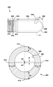
As can be seen in the illustration of Figure 4, the body portion 304 is
defined by a circular inner
surface 402 and circular outer surface 404. Put another way, the transverse
cross-sectional
shape of the inner surface 402 is circular, as is the transverse cross-
sectional shape of the outer
surface 404. Sometimes, the circular inner surface 402 is called "inner skin
of the preform" by
those of skill in the art, while the circular outer surface 404 is called an
"outer skin of the
preform". According to embodiments of the present technology, the thickness of
the body
portion 304 can be said to be circumferentially uneven along substantially the
entirety of the
length of the body portion 304. In the embodiment depicted in Figure 4, four
illustrative points
along the circumference of the body portion 304 have been labelled with the
associated wall
thicknesses: a first point 410, a second point 412, a third point 414 and a
fourth point 416.
Within the illustrated embodiment, the wall thickness of the body portion 304
at the first point
410 and the second point 412 is Ti, a wall thickness at the third point 414 is
T2 and the wall
thickness at the fourth point 416 is T3. Within the illustrated embodiment, T2
< Tl <T3, i.e.
T2 is smaller than Ti, and Ti is smaller than T3. It will be appreciated that
the first point 410,
the second point 412, the third point 414 and the fourth point 416 in Figure 4
have been
selected to illustrate the varying wall thickness. Those of skill in the art
will easily appreciate,
for example, that the wall thickness gradually increases from T2 at the third
point 414 to TI at
the first point 410 and the second point 412. By the same token, the wall
thickness gradually
increases from Ti at the first point 410 and the second point 412 to T3 at the
fourth point 416.
In accordance with embodiments of the present technology, the wall thickness
at any given
portion of the circumference of the body portion 304 is selected based on
behavior that one
desires to achieve during the blow-molding process for the given portion of
the circumference
of the body portion 304. The selection of the wall thickness can be made by a
designer of the
preform 300 when designing the preform 300. More specifically, for the given
portion of the
circumference of the body portion 304 where it is desirable to effect higher
rate of stretching, a
larger wall thickness (i.e. thicker wall) is selected. By the same token, for
the given portion of
the circumference of the body portion 304 where it is desirable to effect
lesser rate of
stretching, a smaller wall thickness (i.e. thinner wall) is selected. Using
the example of the
Figure 3 and Figure 4 embodiment, the wall thickness around the circumference
of the body
portion 304 of the preform 300 has been selected such as to effect, during the
blow-molding: (i)
comparatively least stretching at the third point 414; (ii) comparatively more
stretching at the
first point 410 and the second point 412 in comparison to the third point 414;
and (iii)
CA 02992020 2018-01-09
WO 2017/020116 PCT/CA2016/050701
comparatively most stretching at the fourth point 416 as compared to the first
point 410 and the
second point 412 (and, therefore, compared to the third point 414).
Thus, the inner and outer surfaces of the body portion of the preform are non-
concentric, in the
sense that the circular outer surface 404 has a longitudinal axis Al that is
parallel to but
laterally offset, in an offset dimension (which is vertical in FIG. 4), from a
longitudinal axis A2
of the circular inner surface 402 along substantially the entire length of the
body portion. A
wall thickness accordingly varies circumferentially around the preform 300.
Depicted in Figure 4 is an offset X - an offset between the central axis A2 of
the circular inner
surface 402 and the central axis Al of the circular outer surface 404. In some
embodiments of
the present technology, the offset X can be very small (i.e. marginally
greater than 0 mm), such
as, for example, 0.25 mm. Within these specific implementation, the variation
of the wall
thickness between the thickest wall thickness T3 at the fourth point 416 and
the smallest wall
thickness T2 at the third point 414 can be 0.5 mm. It should be noted,
however, that the offset
X can vary in in other embodiments of the present technology. The specific
offset X can be
selected based, amongst other things, on the size of the bottle to be blow
molded from the
preform 300. In some embodiments of the present technology, the offset X can
vary between
0.2 mm and 4 mm. In other embodiments, the offset X can start in the range of
0.05 mm - 0.1
mm.
As has been alluded to above, the preform 300 can be produced using an
injection molding
system. With reference to Figure 5, there is depicted an exploded view of a
molding stack (or
"mold stack-) that can be used for producing the preform of Figure 3, the
molding stack being
depicted at 500. The molding stack 500 can be used in conjunction with an
injection molding
machine system, discussed below.
The molding stack 500 includes: a core insert 502, a core lock ring 504, a
core cooling tube
506, a cavity insert 508, a gate insert 510 (or "base insert" 510) and a pair
of neck rings 512.
These components of the molding stack 500 are generally known in the art and
will only be
briefly described below as far as modifications thereto are necessary for
manufacturing the
preform 300.
The core insert 502 is configured to define the inner skin of the preform 300.
To that end, the
core insert 502 comprises a core molding surface (not numbered) for defining,
in use, the inner
skin of the preform 300.
16
CA 02992020 2018-01-09
WO 2017/020116 PCT/CA2016/050701
The core lock ring 504 is configured to attach the core insert 502 to a core
plate (not depicted).
In some embodiments of the present technology, the core lock ring 504 can be
omitted and the
core insert 502 can be coupled to the core plate by other means.
A core cooling tube 506 is configured to circulate a cooling fluid within the
core insert 502.
Typically, the cooling fluid (such as water or the like) is circulated through
the core insert 502
(as well as other portions of the molding stack 500) during the appropriate
portions of the
molding cycle, such as during cooling portion thereof. The core cooling tube
506 is coupled, in
use, to a source of a cooling fluid, which is typically a plant-wide supply of
cooling fluid.
The cavity insert 508 is configured to define a portion the outer skin of the
preform 300. More
specifically, the cavity insert 508 is configured to define an outer skin of
the body portion 304
of the preform 300. To that end, the cavity insert 508 comprises a cavity
molding surface (not
numbered) for defining, in use, the appropriate portion of the outer skin of
the preform 300.
The gate insert 510 is configured to define another portion of the outer skin
of the preform 300.
More specifically, the gate insert 510 is configured to define an outer skin
of the base portion
306 of the preform 300. To that end, the gate insert 510 comprises a base
molding surface (not
numbered) for defining, in use, the appropriate portion of the outer skin of
the preform 300. In
some embodiments of the present technology, the gate insert 510 geometry is on
a same
symmetry axis (i.e. longitudinal axis) as the inner diameter of the body
portion 304. In other
words, it can be said that the gate insert 510 and the core insert 502 are
centered with respect to
one another.
The pair of neck rings 512 comprises a pair of complimentary neck ring
inserts, which are
substantially mirror images of each other (these are not separately numbered).
The pair of neck
rings 512 is configured to define the outer skin of the preform 300. More
specifically, the pair
of neck rings 512 is configured to define certain portions of the outer skin
of the neck portion
302 of the preform 300 ¨ such as the threaded portion 310, the support ledge
312 and the
transition portion 314. As in known in the art, in order to release the
various undercuts of the
threaded portion 310 and the support ledge 312, the pair of neck rings 512 is
configured to be
laterally actuatable by known actuators, such as a cam and/or a servo motor
(both not depicted).
The pair of neck rings 512 comprises a neck ring molding surface (not
numbered) for defining,
in use, the appropriate portion of the outer skin of the preform 300.
17
CA 02992020 2018-01-09
WO 2017/020116 PCT/CA2016/050701
In some embodiments of the present technology, the molding stack 500 is
configured to define
a molding cavity (not depicted) for forming the preform 300, the preform 300
having a wall
thickness that varies circumferentially around the preform 300 along
substantially the entirety
of the length of the body portion 304.
In some embodiments of the present technology, the cavity molding surface of
the cavity insert
508 is sized and dimensioned to provide for the circumferentially varying wall
thickness. This
can be achieved by using any suitable machining methods such as, for example,
a lathe
operation. In some embodiments of the present technology, the lathe operation
is executed
using multiple steps having offset axes of rotation of the workpiece. That is,
the workpiece may
be rotated about a first axis of rotation when machining external features of
the cavity and then
rotated about a second axis of rotation, parallel and offset to the first
axis, when machining the
internal molding surface. In accordance with the present embodiment an outer
diameter of the
cavity insert 508 his first machine in a lathe machine (not depicted). Then, a
flange surface (not
numbered) of the cavity insert 508 is aligned. A third step is to move the
cavity insert 508 out
of center in direction of the flange surface with a value of the offset X.
Finally, the cavity insert
508 is turned on the lathe machine using the "new" molding surface center axis
(i.e. offset) to
define the cavity molding surface.
In alternative embodiments of the present technology, the cavity molding
surface can be made
using a milling operation. This is particularly applicable (but not limited)
to those
embodiments, where the length of the cavity molding surface is comparatively
short.
Yet in other embodiments of the present technology, the cavity molding surface
can be made
using by means of splitting the cavity insert 508 in a length-wise direction
and milling the
molding surface (together referred to as a "splitting operation").
Within these embodiments of the present technology, at least a portion of the
base molding
surface of the gate insert 510 can also be sized and dimensioned to provide
for the
circumferentially varying wall thickness. This can be achieved by the same
operations as
described above in respect to the cavity insert 508, namely but not limited
to: lathe operation,
milling operation, splitting operation and the like.
In alternative embodiments of the present technology, the core molding surface
of the core
insert 502 is sized and dimensioned to provide for the circumferentially
varying wall thickness.
This can be achieved by lathe operation. In alternative embodiments, the core
molding surface
18
CA 02992020 2018-01-09
WO 2017/020116 PCT/CA2016/050701
of the core insert 502 can be sized and dimensioned using a turning and
milling operation. In
yet other embodiments, the core molding surface of the core insert 502 can be
sized and
dimensioned using core molding surface of the core insert 502 can be sized and
dimensioned
using a DMLS process. In yet additional embodiments, a hybrid process can be
used ¨ for
example a combination of standard turning (for example, for the base) and DMLS
(for
example, for the core molding surface). Within these embodiments of the
present technology, at
least a portion of the neck ring molding surface of the pair of neck rings 512
can also be sized
and dimensioned to provide for the circumferentially varying wall thickness.
The portion of the
neck ring molding surface that is modified can be the portion responsive for
defining the
transition portion of the neck portion 302 of the preform 300. This can be
achieved by
appropriate changes to the milling operation using a milling machine (not
depicted).
In some embodiments of the present technology, modifications to other
combinations or to all
of the molding surfaces of the core insert 502, the cavity insert 508, the
base insert 510 and the
pair of neck rings 512 can be effected in order to provide for the wall
thickness of the preform
300 that varies circumferentially around the preform 300 along substantially
the entirety of the
length of the body portion 304
In some embodiments of the present technology, the offset of the wall
thickness of the body
portion 304 is achieved by modifying the cavity molding surface of the cavity
insert 508.
Within these embodiments, a center axis of the neck portion 302 is aligned
with a center axis
.. the core insert 502.
In other embodiments of the present technology, the offset of the wall
thickness of the body
portion 304 is achieved by modifying the core molding surface of the core
insert 502. Within
these embodiments, the center axis of the neck portion 302 is aligned with a
center axis the
cavity insert 508.
In some embodiments of the present technology, after being molded and
sufficiently cooled,
the preform 300 is subjected to a blow-molding process to define a final-
shaped blow molded
container, such as the bottle 210. It should be noted that the blow-molding
process does not
have to be carried out at the same location as the molding process, nor does
it need to be carried
out by the same entity that carried out the molding process of the preform
300.
In some embodiments, the process of the blow-molding of the preform 300 is
carried out in a
blow-molding equipment (not depicted). The blow-molding equipment first
reheats the preform
19
CA 02992020 2018-01-09
WO 2017/020116 PCT/CA2016/050701
300 and then subjects it to blow-molding or stretch-blow-molding process. In
some
implementations of the blow-molding process, all portions of the preform 300
can be subjected
to the same level and duration of reheating. In other implementations, the
reheating process can
be executed as a preferential reheating process, where some portions of the
preform 300 is
subjected to higher rates of reheating. How the preferential reheating is
executed is not
particularly limited. For example, the preferential reheating process can be
effected by means
of placing more lamps around or towards certain portions of the preform 300
when the preform
300 is in the reheating oven of the blow-molding equipment. Alternatively, the
preferential
reheating process can be effected by means of placing some of the lamps
further away or closer
to the surface of the preform 300 when the preform 300 is in the reheating
oven of the blow-
molding equipment or orienting the preform in a particular direction toward
lamps.
For example, in some implementations, areas with substantially higher wall
thickness can be
subjected to higher degrees of reheating. For example, the preform 300 can be
subjected to
highest degree of reheating around the thickest fourth point 416 and the
lowest degree of
reheating around the thinnest third point 414, with the first point 410 and
the second point 412
a degree of reheating that is in-between the degree of reheating for the third
point 414 on one
end of the spectrum (point 414 being the thinnest and, therefore, receiving
the least reheating
energy) and the fourth point 416 on the other end of the spectrum (point 416
being the thickest
and, therefore, receiving the most reheating energy).
It should be noted that the preferential heating is an optional feature. As a
matter of fact,
embodiments of the present technology can lead to a technical effect where no
preferential
heating is required and where the blow molding behavior of the preform 300 is
achieved via the
circumferential wall thickness variations. Having said that, in some
embodiments, it may be
beneficial to add an additional technical effect by executing preferential
reheating as discussed
above.
In some embodiments, in order to locate the preform 300 in the blow mold (not
depicted), the
locating feature 316 is used. More specifically, the locating feature 316 can
be used for
orienting the preform 300 within either the reheating oven (to effect
preferential reheating, for
example) and/or in the blow mold. This can be particularly useful (but not
limited to) in those
embodiments, where the preform 300 is used for blow molding into a non-
symmetrical
container, such as the bottle 210. The locating feature 316 can be used to
orient those portions
of the preform 300 that have higher thickness relative to those portions of
the blow mold,
CA 02992020 2018-01-09
WO 2017/020116 PCT/CA2016/050701
where the wall of the preform 300 would have to "travel" further distance to
reach the final
shape of the bottle 210. In alternative embodiments of the present technology,
a feature other
than the locating feature 316 can be used for positively locating the preform
300. Positive
locating of the preform 300 can be executed by means of positively locating a
start of the
threaded portion 310 and the like.
Even though embodiments of the present technology have been described using an
example of
a so-called two-stage injection blow molding process, they are not so limited.
As such,
teachings presented herein can be equally applied to a single stage process,
where the preform
300 is manufactured and substantially immediately blow-molded into the final
shaped container
- with or without additional reheating. In other words, rather than storing
and/or transporting
the preform 300 after it is molded, the preform 300 is blow molded into a
hybrid injection ¨
blow ¨ molding equipment or in a blow molding machine located in vicinity of
the injection
molding machine.
It should be further noted that even though embodiments of the present
technology have been
described using an example of the offset of the wall thickness being
substantially along the
entirety of the body portion 304, the offset can also be effected in portions
of the transition
portion of the neck portion 302 and portions of the base portion 306.
Additionally, even though
embodiments of the present technology have been described using an example of
the offset
molding surfaces being used to define the circular inner surface 402 and a
circular outer surface
404 with an offset therebetweem (i.e. as means to define non-even
circumferential wall
thickness), in additional embodiments, the non-even circumferential wall
thickness can be
achieved by other means, for example, by means of non-cylindrical shaped outer
molding
surface of the core insert 502, non-cylindrical shaped inner molding surface
of the cavity insert
508, etc.
In some embodiments of the present technology, the base portion 306 is defined
between an
inner end surface 440 and an outer end surface 442 (both depicted in Figure 3)
that extend from
the circular inner surface 402 and the circular outer surface 404 of the body
portion 304,
respectively, coaxially therewith. The base thickness of the base portion is
defined between the
inner end surface 440 and the outer end surface 442. In some embodiments, the
base thickness
also varies circumferentially around the preform.
Embodiments of the present technology can lead to a technical effect, whereby
the preform 300
having a wall thickness that varies circumferentially around the preform 300
along substantially
21
CA 02992020 2018-01-09
WO 2017/020116 PCT/CA2016/050701
the entirety of the length of the body portion 304 is designed for producing
the so-called off-set
bottle (such as the bottle 210). Compared to the typical approach to making a
preform for such
the off-set bottle, which is typically made with a comparatively thicker wall
thickness, to
compensate for un-even blowing of various parts of the preform, the preform
300 designed in
accordance with present technology may result in overall resin weight savings
compared to a
typical prior art approach. In a sense, embodiments of the present technology
contemplate
placing comparatively more material in those circumferential portions of the
body portion 304
that will travel more during the blow-molding process and comparatively less
material in those
circumferential portions of the body portion 304 that will travel less during
the blow-molding
process. In other words, the coordination between designing the
circumferential wall thickness
of the body portion 304 of the preform 300 with the blow-molding behavior when
producing an
off-set bottle can lead to a technical effect of overall weight savings
compared to the prior art
approaches.
With reference to FIG. 6, there is depicted a non-limiting embodiment of an
injection molding
system 600 that may be used to produce the preform 300 of FIG. 3. The
injection molding
system 600 comprises a fixed platen 602 and a movable platen 604. The
injection molding
system 600 further comprises an injection unit 606 for plasticizing and
injecting molding
material. The movable platen 604 is movable along an operational axis of the
mold, in a spatial
dimension X, towards and away from the fixed platen 602, by means of stroke
cylinders (not
.. shown) or any other suitable means. Clamp force (also referred to as
closure or mold closure
tonnage) can be developed within the injection molding system 600, for
example, by using tie
bars 608, 610 and a tie-bar clamping mechanism 612, as well as (typically) an
associated
hydraulic system (not depicted) that is usually associated with the tie-bar
clamping mechanism
612.
A first mold half 614 is associated with the fixed platen 602 and a second
mold half 616 is
associated with the movable platen 604. In the specific non-limiting
embodiment of FIG. 6, the
first mold half 614 comprises a plurality of mold cavities 618 (each being
referred to
generically as mold cavity 618; the plurality being referred to collectively
as mold cavities
618). As such, the first mold half 614 can be generally thought of as a "mold
cavity half." As
will be appreciated by those of skill in the art, the mold cavities 618 may be
formed from
suitable mold inserts, such as inserts 508 and 510 of FIG. 5, or any other
suitable means.
22
CA 02992020 2018-01-09
WO 2017/020116 PCT/CA2016/050701
The second mold half 616 comprises a plurality of mold cores (or "core
pieces")
complementary to the plurality of mold cavities 618, the mold cores being
referred to
generically and collectively as mold core(s) 620. As such, the second mold
half 616 can be
generally thought of as a "mold core half." As will be appreciated by those of
skill in the art,
the one or more mold cores 620 may be formed from suitable mold inserts, such
as core insert
502 of FIG. 5, or any other suitable means.
The first mold half 614 may be coupled to the fixed platen 602 by a suitable
fastener (not
depicted) or other means. Similarly, the second mold half 616 may be coupled
to the movable
platen 604 by a suitable fastener (not depicted) or other means. The first and
second mold
halves 614 and 616 may collectively be referred to as a "mold."
It should be understood that, in an alternative non-limiting embodiment, the
position of the first
mold half 614 and the second mold half 616 can be reversed and, as such, the
first mold half
614 can be associated with the movable platen 604 and the second mold half 616
can be
associated with the fixed platen 602. Moreover, in some alternative
embodiments, the platen
602 may not be fixed but rather may as well be movable in relation to other
components of the
molding system 600.
FIG. 6 depicts the first mold half 614 and the second mold half 616 in a so-
called "mold open
position" where the movable platen 604 is positioned generally away from the
fixed platen 602
and, accordingly, the first mold half 614 is positioned generally away from
the second mold
half 616. In the mold open position, a molded article (not depicted) can be
removed from the
first mold half 614 and/or the second mold half 616. In a so-called "mold
closed position" (not
depicted), the first mold half 614 and the second mold half 616 are urged
together, by means of
movement of the movable platen 604 towards the fixed platen 602, and cooperate
to define (at
least in part) a molding cavity (not depicted) into which the molten plastic
(or other suitable
molding material) can be injected. It should be appreciated that one of the
first mold half 614
and the second mold half 616 can be associated with a number of additional
mold elements,
such as for example, one or more leader pins (not depicted) and one or more
leader bushings
(not depicted), the one or more leader pins cooperating with one more leader
bushings to assist
in alignment of the first mold half 614 with the second mold half 616 in the
mold closed
position, as is known to those of skill in the art.
The molding system 600 further includes a preform handling apparatus 622
comprising a beam
624, a carriage 625, an actuating arm 626 and a take-off device 628. The beam
624 is attached
23
CA 02992020 2018-01-09
WO 2017/020116 PCT/CA2016/050701
to the fixed platen 602 and extends in a spatial dimension denoted Z in FIG.
6, which may be
horizontal. As such, the example beam 624 may be referred to as a "Z beam" or
"horizontal
beam." The carriage 625 is movable in spatial dimension Z, e.g. rides along
the beam 624 in a
linear trajectory, possibly being driven by an actuator such as a servo-
electric driven belt drive
(not expressly depicted). The actuating arm 626 is coupled to the carriage
625, and the take-off
device 628 is coupled to the actuating arm 626. The preform handling apparatus
622 may be
considered as a form of robot.
The take-off device 628 comprises an end-of-arm tool (EOAT) plate 629 (or
simply "plate
629") having a plurality of preform carriers attached thereto. The preform
carriers are referred
to herein generically and collectively as preform carrier(s) 630. For clarity,
the reason that plate
629 may be referred to as an end-of-arm tool plate 629 is that it is attached
at a distal end of
actuating arm 626.
Generally speaking, the purpose of each of the preform carriers 630 is to
retrieve a preform
from one of the mold halves. In this example, each preform carrier 630 is
designed to remove a
preform from one of the mold cores 620 of mold core half 616. Therefore, the
preform carriers
630 in this embodiment may each take the form of a tube that is configured
(e.g. sized and
shaped) to receive and hold a preform 300 by its outer cylindrical surface 404
(see FIG. 4). The
outer surface 404 may accordingly be referred to as the "contact surface" 404
of the preform in
the present embodiment. Although perhaps less common, in alternative
embodiments, a
preform carrier may instead be designed to remove a preform from a respective
mold cavity
618 of mold cavity half 614. In such embodiments, the preform carrier may be
configured (e.g.
sized and shaped) to hold a preform 300 by its inner cylindrical surface 402
(see FIG. 4), e.g.
may take the form of a cylindrical rod that fits inside the preform. In that
case, the inner
cylindrical surface 402 of the preform, rather than the outer cylindrical
surface 404, may be
considered to be "contact surface- of the preform.
The exact number of preform carriers 630 on plate 629 is not particularly
limited. For example,
if a three-position post mold cooling cycle is to be implemented and if the
molding system 600
comprises 72 instances of mold cavity 618 (for example, 12 rows of 6), the
take-off device 628
could comprise 216 preform carriers 630 (i.e. twelve rows of 18). In another
embodiment, the
take-off device 628 may comprise twelve rows of twenty-five preform carriers
630, for a total
of three hundred preform carriers 630. Other configurations are, of course,
also possible and
may be dictated by business considerations of an entity managing the molding
system 600.
24
CA 02992020 2018-01-09
WO 2017/020116 PCT/CA2016/050701
Referring again to FIG. 6, it will be appreciated that the take-off device 628
is shown in an
outboard position, outboard of the two mold halves 614 and 616. In this
position, the take-off
device 628 does not obstruct the opening and closing of the mold along its
operational axis in
spatial dimension X. The take-off device 628 also has an inboard position (not
expressly
depicted in FIG. 6) which is attainable when the mold is in the "mold open"
position, with
mold halves 614, 616 being separated (as in FIG. 6). In the inboard position,
the take-off device
628 is aligned with the mold half 616 so that the preform carriers 630 can
retrieve freshly
molded preforms from the mold cores 620. As such, the inboard position of the
take-off device
628 may be referred to as the "preform-loading" or "inboard preform-loading"
position of take-
off device 628.
In operation, after a batch of preforms has been molded and the mold has been
opened by
separating mold halves 614, 616 in spatial dimension X (as in FIG. 6), the
take-off device 628
may be moved, in spatial dimension Z, from its outboard position (as shown in
FIG. 6) to the
inboard preform-loading position adjacent to the mold half 616. The
positioning of the take-off
device 628 in the inboard position is such that each of the empty preform
carriers 630 aligns
with a mold core, as will be discussed in more detail below. The preforms are
then retrieved,
i.e. are transferred into the preform carriers 630, and the take-off device
628 is moved back to
its outboard position in spatial dimension Z. The now-empty mold can
thereafter be closed and
clamped for the next molding cycle. As such, the take-off device 628
reciprocates in spatial
dimension Z, in alternating sequence with the opening and closing of the mold
halves 614, 616
in spatial dimension X.
It should be appreciated that injection molding system 600 may comprise a
number of
additional components, such as a hot runner, a treatment device for treating
preforms held by
preform carriers 630, and so forth, which are omitted from FIG. 6 brevity. It
should also be
understood that the molding system 600 may have other configurations. The
description of the
example system presented above has been provided as an example only and is not
intended to
be limiting. In other non-limiting embodiments of the present invention, the
molding system
600 can have other configurations with more or fewer components.
It may be considered desirable to be able to use the injection molding system
for molding, on
one occasion, preforms having a body portion whose wall is substantially
uniform in thickness
about the circumference of the preform (e.g. such as preform 100 of FIG. 1),
and to use the
same injection molding system, on another occasion, for molding preforms 300
having a body
CA 02992020 2018-01-09
WO 2017/020116 PCT/CA2016/050701
portion whose wall varies in thickness about a circumference of the preform
(e.g. such as
preform 300 of FIG. 4). The injection molding system 600 may however be ill-
suited for such
multipurpose use (at least in a default configuration of the system 600), as
placement of the
take-off device 928 into a standard inboard preform-loading position may cause
the preform
carriers 630 to be misaligned with preforms of the latter type. This is
illustrated in FIGS. 7 and
8.
FIGS. 7 and 8 are transverse cross-sectional views of a preform carrier 630 in
the molding
system 600 of FIG. 6 during retrieval of a preform 700 and a preform 800,
respectively, from a
mold core 620. The cross-sections of FIGS. 7 and 8 are each taken through the
body portion of
preform 700 and 800 respectively (analogous to the body portion 104 of the
preform 100 of
FIG. 1). In particular, FIG. 7 illustrates the case where the preform carrier
630 retrieves a
conventional preform 700 whose wall thickness is substantially uniform about
the
circumference of the preform, i.e. whose cylindrical outer surface 702 is
concentric with its
cylindrical inner surface 714 in the body portion of the preform 700. FIG. 8
illustrates a
different case where the preform carrier 630 retrieves a preform 800 whose
wall thickness
varies about the circumference of the preform, i.e. whose cylindrical outer
surface 802 is non-
concentric with (offset from) the cylindrical inner surface 814 in the body
portion of the
preform 800 (like preform 300 of FIG. 4).
As shown in to FIG. 7, the preform carrier 630 is aligned with mold core 620,
in the sense that
they both share a common longitudinal axis C. Moreover, it can be seen that
the cylindrical
inner surface 632 of the preform carrier 630 (also referred to as the "contact
surface 632" of the
preform carrier 630, because it comes into contact with the preform during
preform retrieval) is
concentric with, and closely surrounds, the outer cylindrical contact surface
702 of the preform
700. A slight circumferential gap 704 may exist between surfaces 702 and 632
for clearance
purposes, e.g. to reduce a risk of damage to the contact surface 702 of the
preform as the
preform 700 is received within the preform carrier 630 during preform
retrieval. The preform
carrier 630 is said to be aligned with preform 700 in FIG. 7 because the
contact surface 632 of
the preform carrier 630 is concentric with the contact surface 702 of the
preform 700.
In contrast, in FIG. 8, the preform carrier 630 is misaligned with preform
800, in the sense that
the contact surface 632 of the preform carrier 630 is non-concentric with the
contact surface
802 of the preform 800. In particular, although the contact surface 632 of the
preform carrier
630 remains aligned (concentric) with the mold core 620 in this scenario (both
sharing common
26
CA 02992020 2018-01-09
WO 2017/020116 PCT/CA2016/050701
longitudinal axis C), the cylindrical outer surface 802 of the preform 800 is
non-concentric with
the preform carrier 630. The reason is that the outer surface 802 of the
preform is now centered
about a longitudinal axis D, which is parallel to but offset from axis C in
spatial dimension Y
(mutually orthogonal spatial dimensions X, Y and Z in FIG. 8 corresponding to
those of FIG.
6). Put another way, the non-concentricity of the outer surface 802 of the
body portion of the
preform 800 with the inner surface 814 of the body portion of the preform 800
causes the
former to be out of alignment with the mold core 620 and thus the preform
carrier 630.
As a result of the misalignment between the preform 800 and preform carrier
630, in one
arcuate section 806 of the preform wall, there may be a gap 804 between
contact surfaces 632
and 802m i.e. the preform 800 may be poorly supported or even unsupported
(e.g. loose within
the preform carrier) in that area. This may be particularly true at the
thinnest section 812 of the
preform wall, i.e. at the topmost wall section in FIG. 8. In contrast, on the
opposite side of the
preform 800, in arcuate section 808, there may either be no gap between
contact surfaces 632
and 802, or worse, the inwardly facing contact surface 632 in section 808 may
physically
impinge upon the contact surface 802 of the preform 800. This may be
particularly true at the
thickest section 810 of the preform wall, i.e. at the bottommost wall section
in FIG. 8. The
latter may disadvantageously result in damage to the preform 800 due to
contact between the
preform carrier 530 and the outer surface of the preform 800 during an
attempted retrieval of
the preform 800 from mold core 620.
With reference to FIG. 9, there is depicted a non-limiting embodiment of an
injection molding
system 900 designed to limit or avoid the misalignment problems described
above in
conjunction with FIG. 8. The injection molding system 900 is in many respects
similar to the
injection molding system 600 of FIG. 6. For example, the following components
of system 900
may function in a manner analogous to their counterparts in the injection
molding system 600
of FIG. 6 and will therefore not be described in any detail here: platens 902
and 904; injection
unit 906; tie bars 908, 910; tie-bar clamping mechanism 912; mold halves 914
and 916
(collectively forming a "mold"); mold cavities 918; and mold cores 920.
However, the preform
handling apparatus 922 of molding system 900 has been modified, as described
below, from its
counterpart preform handling apparatus 622 of FIG. 6 with a view to limiting
or eliminating the
misalignment problems discussed above.
At a high level, the preform handling apparatus 922 of FIG. 9 serves a similar
purpose as
preform handling apparatus 622 of FIG. 6, i.e. to retrieve freshly molded
preforms from one of
27
CA 02992020 2018-01-09
WO 2017/020116 PCT/CA2016/050701
the mold halves (in this example, the core half) in preparation for a
subsequent molding cycle.
As with preform handling apparatus 622 of FIG. 6, the preform handling
apparatus 922
includes a beam 924 extending in spatial dimension Z (which may be
horizontal), a carriage
925 that rides on beam 924, an actuating arm 926 coupled to the carriage 925,
and a take-off
device 928 comprising an end-of-arm tool plate 929 with a plurality of preform
carriers 930
attached thereto. Also, as with preform handling apparatus 622, the preform
handling apparatus
922 may be considered as a form of robot.
However, unlike the preform handling apparatus 622 of FIG. 6, the preform
handling apparatus
922 incorporates a take-off device alignment mechanism 923. The purpose of the
take-off
device alignment mechanism 923 is to maintain an alignment of each preform
carrier 930 on
end-of-arm tool plate 929 that is being used to retrieve a freshly molded
preform with a contact
surface of its respective preform, regardless of whether the cylindrical inner
and outer surfaces
of the body portion of the preform are concentric or non-concentric. As will
be described, this
may be achieved by setting the inboard preform-loading position of the take-
off device 928
based on whether the inner and outer surfaces of a body portion of the preform
are concentric
or non-concentric.
In FIG. 9, the take-off device alignment mechanism 923 is schematically
represented as part of
the carriage 925. This is merely to convey the fact that, in the illustrated
embodiment, the take-
off device alignment mechanism 923 uses the carriage 925 to adjust the inboard
preform-
loading position of the take-off device 928, in spatial dimension Z, for the
above-noted
alignment purposes. In practice, the adjustment may actually be achieved
through suitable
modification, or programming, of a controller that sends commands or control
signals for
setting the carriage position via an actuator (such as a servo-driven belt
drive, which is not
expressly depicted). Nevertheless, the representation of the take-off device
alignment
mechanism 923 as forming part of carriage 925 in FIG. 9 should not be
understood to mean that
all embodiments of take-off device alignment mechanisms necessarily form part
of a carriage
or use a carriage to adjust the inboard preform-loading position of the take-
off device. Other
embodiments may use different mechanisms, as will be described. The adjustment
mechanism
may be operable to make adjustments automatically, e.g. based on mold ID
and/or preform
information. The adjustment mechanism may be operable to adjust the preform-
loading
position based on information entered via a human-machine interface, such as
mold ID,
preform information, or offset values.
28
CA 02992020 2018-01-09
WO 2017/020116 PCT/CA2016/050701
Operation of the preform handling apparatus 922 of FIG. 9 is illustrated in
FIGS. 10-13. FIG.
illustrates movement of the take-off device 928, by preform handling apparatus
922, for
retrieving, from mold half 916, preforms 1000 whose body portions have
concentric inner and
outer surfaces (referred to below as "circumferentially uniform" preforms).
FIG. 11 illustrates
5 alignment between a preform carrier 930 and a circumferentially uniform
preform 1000 that
results from the movement shown in FIG. 10. FIG. 12 illustrates movement of
the take-off
device 928, by preform handling apparatus 922, for retrieving, from mold half
916, preforms
1200 whose body portions have non-concentric (offset) cylindrical inner and
outer surfaces
(such preforms referred to below as "circumferentially offset" preforms). FIG.
13 illustrates
10 alignment between a preform carrier 930 and a circumferentially offset
preform 1200 that
results from the movement shown in FIG. 12.
In FIGS. 10-13, mutually orthogonal spatial dimensions X, Y and Z are
consistent with the
mutually orthogonal spatial dimensions X, Y and Z, respectively, of FIG. 9.
Beginning with FIG. 10, the take-off device 928 is initially in an outboard
position, which
corresponds to the outboard position of the take-off device 928 shown in FIG.
9. For clarity, the
take-off device 928 is depicted schematically in FIG. 10 to show only a single
example preform
carrier 930. It will be appreciated that the take-off device 928 may in fact
have many similar
preform carriers 930 attached thereto, e.g. arranged in rows and/or columns.
It will also be
appreciated that the depiction of example preform carrier 930 in FIG. 10 is
not to scale with the
depicted end-of-arm tool plate 929 to which it is attached. The preform
carrier 930 is tubular in
this embodiment and is sized and shaped appropriately for holding the
circumferentially
uniform preform 1000 by an outer cylindrical surface.
FIG. 10 includes a schematic depiction of mold half 916, showing a single
example mold core
920. It will be appreciated that the mold half 916 may in fact have many
similar mold cores 920
attached thereto, e.g. arranged in rows and/or columns. The number of mold
cores 920 may be
a divisor of the number of preform carriers 930 on the take-off device 928
(given that take-off
device 928 may be able to simultaneously hold multiple batches of recently
molded preforms at
different stages of cooling). A freshly molded, circumferentially uniform
preform 1000 is
depicted in FIG. 10 in association with the mold core 920. The mold half 916
is understood to
be in a mold-open position, which corresponds to the mold open position of
FIG. 9.
When it is time for the preform 1000 to be retrieved from the mold core 920,
the take-off
device 928 is translated (moved), along a linear trajectory T (i.e. in spatial
dimension Z), from
29
CA 02992020 2018-01-09
WO 2017/020116 PCT/CA2016/050701
the outboard position to an inboard preform-loading position, which is
depicted in dashed lines
and is referred to as "inboard position A" in FIG. 10. Movement of the take-
off device 928 may
be effected by a controller sending control signals or commands to an actuator
that drives
carriage 925 along beam 924 (FIG. 9). The distance moved by the take-off
device 928 between
the outboard position and inboard position A is denoted DI.
It will be appreciated that, when the take-off device 928 reaches the inboard
position A, the
preform carrier 930 will be aligned (in this example, in spatial dimension Z,
as well as
dimension Y) with the mold core 920, and accordingly, will also be aligned
with the
circumferentially uniform preform 1000 sitting on mold core 920. This is shown
in greater
detail in FIG. 11.
FIG. 11 is a transverse cross-sectional view of the preform carrier 930 when
the take-off device
928 is in the inboard preform-loading position A of FIG. 10. The cross-section
of FIG. 11 is
taken through the body portion of preform 1000 as the preform carrier 930
retrieves the
preform 1000 from the mold core 920. It can be seen that the preform carrier
930 is concentric
with the mold core 920, in the sense that both share a common longitudinal
axis CC. Because
the preform 1000 is circumferentially uniform, the preform carrier 930 is also
aligned with the
contact surface 1002 of preform 1000 (i.e. cylindrical inner surface 932 of
the preform carrier
930 is concentric with the cylindrical outer surface 1002 of the preform
1000).
Turning to FIG. 12, whose conventions match those of FIG. 10, it is presumed
that the injection
molding system 900 has been reconfigured for molding different preforms, i.e.
circumferentially offset preforms 1200, as shown in association with the mold
core 920' on
mold half 916. Reconfiguration may entail substitution of suitable cavity
inserts and/core
inserts into mold half 914 and/or mold half 916 in place of the ones used
previously to mold
preforms 1000; as such, mold core 920' may be identical to, or different, from
mold core 920.
As part of the conversion, the take-off device alignment mechanism 923 adjusts
the inboard
preform-loading position from inboard position A of FIG. 10 to inboard
position B of FIG. 12,
discussed below.
In some embodiments, adjustment may be facilitated using an IIMI. An operator
may use the
HMI to set or adjust a value that determines the stopping position for the
robot, e.g. by way of
an encoder. In other embodiments, adjustment of the inboard preform-loading
position may be
done by mechanical adjustments. For example, alignment pins (or other
adjustment devices)
could be used to adjust the end-of-arm tool plate 929 position on actuating
arm 926. Different
CA 02992020 2018-01-09
WO 2017/020116 PCT/CA2016/050701
pins could be used for different degrees of offset, depending upon the degree
of offset between
the cylindrical inner and outer surfaces of the preforms to be handled.
A possible alternative could be to provide alignment holes on mold half 916
that are specific to
the degree of offset between the inner and outer surfaces of the preforms to
be handled.
FIG. 13 illustrates an example preform 1200 that may be produced by the
reconfigured mold.
As illustrated, the preform 1200 has a cylindrical outer surface 1202, which
is non-concentric
with longitudinal axis CC' of the mold core 920'. That is, the outer surface
1202 is centered
about a longitudinal axis DD, which is parallel to but offset, in spatial
dimension Z (the "offset
dimension" in this example), from axis CC', by a distance XX. Notably, in this
embodiment,
the offset dimension is intentionally aligned with the dimension in which the
take-off device
928 moves (i.e. spatial dimension Z). This alignment can be achieved through
suitable selection
and/or suitable orientation of mold cavity inserts and/or mold core inserts
used to mold the
preform 1200. The reason for the alignment is to allow the take-off device
alignment
mechanism 923 to easily adjust or redefine the inboard preform-loading
position from inboard
position A to inboard position B by adjusting a stop position of carriage 925
on beam 924, as
discussed below.
Referring again to FIG. 12, when it is time for the circumferentially offset
preform 1200 to be
retrieved from the mold core 920', the take-off device 928 is translated
(moved), along a linear
trajectory T (i.e. in spatial dimension Z), from the same initial outboard
position as in FIG. 10
to a new inboard preform-loading position, which is denoted in dashed lines as
"inboard
position B- in FIG. 12. Notably, inboard position B differs from inboard
position A of FIG. 10
in that the former is offset from the latter by the offset amount XX depicted
in FIG. 13, i.e. by
the offset distance between longitudinal axis CC' of the cylindrical inner
surface 1214 of the
preform and parallel longitudinal axis DD of the outer surface 1202 of the
preform 1200. The
offset amount XX may be one-half of a difference in wall thickness between a
thickest wall
1320 of the body portion of the preform 1200 (at the left side of FIG. 13) and
a thinnest wall
1220 of the body portion of the preform 1200 (at the right side of FIG. 13).
Thus, when the take-off device 928 reaches the inboard preform-loading
position B, the contact
surface 932 of preform carrier 930 will be aligned (concentric) with the outer
surface 1202 of
the circumferentially offset preform, but will no longer be aligned with the
mold core 920'. This
is shown in greater detail in FIG. 13.
31
CA 02992020 2018-01-09
WO 2017/020116 PCT/CA2016/050701
Referring to FIG. 13, whose conventions match those of FIG. 11, it can be seen
that the inner
cylindrical surface 932 of preform carrier 930 is aligned (concentric) with
outer cylindrical
contact surface 1202 of the circumferentially uniform preform 1000 (albeit not
with mold core
920). This may alternatively be referred to as aligning the preform carrier
930 with the contact
surface 1202 of the preform 1000. In this position, a risk of damage to an
outer surface 1202 of
the preform 1200 during preform retrieval by preform carrier 930 may be
reduced in
comparison with the scenario depicted in FIG. 8 for example.
It will be appreciated that, in the above example, the offset dimension (i.e.
the spatial
dimension in which the cylindrical inner and outer surfaces of the body
portion of the preform
are offset from one another) is aligned with the dimension of translation
(movement) of the
take-off device, i.e. spatial dimension Z in this example. This approach may
yield a number of
benefits.
For example, when the injection molding system is being changed from molding
circumferentially uniform preforms to molding circumferentially offset
preforms or vice-versa,
there may be no need to change the hardware of the end-of-arm tool and/or take-
off device (e.g.
mounting and/or adjustment of an end-of-arm tool plate and/or individual
preform carriers). All
that may need to be done is to adjust the inboard preform-loading position,
e.g. through
adjusting a stop position of a take-off device via the take-off device
alignment mechanism 923.
The time required for changeover from molding preforms having a constant wall
thickness to
molding offset preforms having a variable wall thickness may be reduced, e.g.
in comparison to
embodiments wherein take-off device hardware changes must be made manually to
effect such
a changeover.
Further, the same end-of-arm tool plate may be usable for both
circumferentially uniform and
circumferentially offset preforms. As a result, the risk of mistakenly using a
plate intended for a
.. different purpose may be reduced.
Finally, the above approach may allow a standard treatment device, as may
normally be used
for treating (e.g. blowing air into) circumferentially uniform preforms, to
also be usable for
treating circumferentially offset preforms. The reason is that the cylindrical
inner surface 1014
of a circumferentially uniform preform 1000 being held in inboard position A
(see FIGS. 10
and 11) may be positioned in the same place as the cylindrical inner surface
1214 of a
circumferentially offset preform 1000 held in inboard position B (see FIGS. 12
and 13).
32
CA 02992020 2018-01-09
WO 2017/020116 PCT/CA2016/050701
Various alternative embodiments are possible.
For example, in the embodiment described in conjunction with FIGS. 9-13, the
offset
dimension (i.e. the spatial dimension in which the cylindrical inner and outer
surfaces of the
body portion of the preform are offset from one another) is aligned with the
dimension of
movement of the take-off device 928 (spatial dimension Z in the example). It
should be
appreciated that, although such alignment may afford certain benefits as
discussed above, it is
not required for the offset dimension to match the dimension of movement of
the take-off
device in all embodiments.
For example, a possible alternative solution for the misalignment shown in
FIG. 8 could be to
reposition the preform carrier 630 (FIG. 6), in a spatial dimension that is
orthogonal to the
dimension of movement of the take-off device (e.g. in FIG. 8, downwardly in
spatial dimension
Y), relative to the take-off plate to which the preform carrier 630 is
attached. In particular, if
the preform carrier 630 were repositioned on the plate so that, when the take-
off device is in the
inboard preform-loading position, the inwardly facing cylindrical contact
surface 632 of the
preform carrier 630 were centered about longitudinal axis D of FIG. 8 rather
than longitudinal
axis C, alignment could be achieved. Alternatively, the entire end-of-arm tool
plate 629
comprising the take-off device 628 (see FIG. 6) could be moved as a unit
relative to the arm
626 in spatial dimension Y, or perhaps swapped for a different plate on which
all preform
carriers have been so repositioned in spatial dimension Y. The moving or
swapping a plate as a
whole might be considered less time consuming than adjusting the preform
carrier positions
individually. A possible cost of any of the approaches introduced in this
paragraph may be lost
system productivity, if it is required to take the molding system offline to
reposition the
preform carriers or move or swap the end-of-arm tool plate, for example. This
cost may be
considered acceptable in some cases.
It should further be appreciated that, in some alternative embodiments, each
preform carrier
may be designed to remove a preform from a respective mold cavity 918 of mold
cavity half
914 rather than from a mold core 920, 920 of mold half 916. In such
embodiments, the preform
carrier may be configured (e.g. sized and shaped) to hold a preform 300 by a
contact surface
forming part of the inner cylindrical surface of (the body portion of) the
preform. The take-off
device alignment mechanism in such embodiments may be designed to maintain the
preform
carrier in alignment with the inner cylindrical contact surface of the preform
regardless of any
33
H-8055-1-WO
offset between a longitudinal axis of the cylindrical inner surface of the
preform and a
longitudinal axis of the cylindrical outer surface of the preform.
Description of the non-limiting embodiments of the present technology provides
examples of the
present technology, and these examples do not limit the scope of the present
technology. The
concepts described above may be adapted for specific conditions and/or
functions, and may be
further extended to a variety of other applications that are within the scope
of the present
technology. Having thus described the non-limiting embodiments of the present
technology, it
will be apparent that modifications and enhancements are possible without
departing from the
concepts as described.
34
Date Recue/Date Received 2021-05-06