Note: Descriptions are shown in the official language in which they were submitted.
CA 02992023 2018-01-10
DESCRIPTION
Title of the Invention:
ENCAPSULATED AGENT AND VARIABLE VISCOSITY FLUID
Technical Field
[0001] The invention relates to an encapsulated agent that reduces
viscosity of a
fluid, and to a variable viscosity fluid that uses the encapsulated agent.
Background Art
[0002] In association with concerns about supply of energy, shale gas has
attracted
attention as new energy (for example, see NPTL 1). The shale gas is natural
gas
contained in a shale stratum. However, the shale gas is so-called
unconventional
natural gas, which makes it difficult to collect the shale gas from the earth.
[0003] Accordingly, as a method of collecting the shale gas from the earth,
a
hydrofracturing technique has drawn attention (for example, see NPTL 2). The
hydrofracturing technique is a method of artificially fracturing a reservoir
rock in the
vicinity of a well by applying pressure to a fracturing fluid with which the
inside of the
well is filled. At the time of fracturing of the reservoir rock, cracks
(fractures) occur,
which allows the shale gas to be collected through the cracks.
[0004] The fracturing fluid contains a plurality of particulate substances
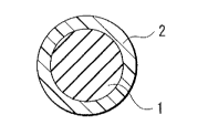
(proppants)
to prevent the cracks from getting blocked after fracturing of the reservoir
rock. The
plurality of particulate substances are particles of sand, etc.
[0005] In the event of occurrence of the cracks, the fracturing fluid
applied with
pressure comes into the cracks, and accordingly the plurality of particulate
substances
contained in the fracturing fluid also come into the cracks. As a result, the
cracks are
retained as they are even if the application of pressure to the fracturing
fluid is stopped.
[0006] Further, the fracturing fluid contains a viscosity-reducing agent to
collect the
fracturing fluid after fracturing of the reservoir rock.
1
CA 02992023 2018-01-10
[0007] To ensure
that the plurality of particulate substances easily come into the
cracks, the viscosity of the fracturing fluid is desirably high prior to
fracturing of the
reservoir rock. Meanwhile, after the plurality of particulate substances come
into the
cracks, to facilitate collection of the fracturing fluid with which the inside
of the well is
filled, the viscosity of the fracturing fluid is desirably low after the
fracturing of the
reservoir rock. Therefore, the viscosity-reducing agent (a breaker) having a
function
of reducing the viscosity of the fracturing fluid (a viscosity-reducing
function) is in use.
[0008] Concerning a
configuration of the viscosity-reducing agent, specific
proposals have been already made. For example, to exercise the viscosity-
reducing
function in the middle of the use of the fracturing fluid, a viscosity-
reducing agent (an
encapsulated agent) having a capsule structure is in use (for example, see PTL
1). In
such an encapsulated agent, a material having the viscosity-reducing function
is covered
with a coating film that is decomposed utilizing a hydrolysis reaction. The
coating
film includes poly (2-alkyl cyanoacrylate), etc. as a material to be
decomposed utilizing
the hydrolysis reaction.
Citation List
Non-patent Literature
[0009] NPTL 1: Ken
Ihara, "The Impact of the Shale Gas", Analysis, 2010.5, Vol.
44, No. 3, PP. 15-38, Internet URL:
http://oilgas-info.j ogmec.go.jp/pdf/3/3574/201005#015a.pdf
NPTL 2: Ken Ihara, "The History and Impact of the Hydrofracturing Technique",
Analysis, 2011.5, Vol. 45, No. 3, pp. 17-30, Internet URL:
http://oilgas-info.j ogmec.go.jp/pdf/4/4370/201105#017a.pdf
Patent Literature
[0010] PTL 1: International Publication No. WO 99/061747
Summary of the Invention
[0011] Use of an
encapsulated agent as a viscosity-reducing agent without limiting
2
CA 02992023 2018-01-10
an application thereof to a hydrofracturing technique is extremely
advantageous in
controlling viscosity of a fluid. However, in a case where the encapsulated
agent is
used, it is desired to sufficiently reduce the viscosity of the fluid in a
short amount of
time at intended timing, and therefore, there is still room for improvement
concerning a
viscosity-reducing function of the encapsulated agent.
[0012] It is therefore desirable to provide an encapsulated agent and a
variable
viscosity fluid that are able to exercise a superior viscosity-reducing
function.
[0013] As a result of considerations with a concentrated mind to accomplish
the
above-described objective, the inventors have found that, in an encapsulated
agent that
includes a central part containing a viscosity-reducing material and an outer
part, the
above-described problem is solved by causing the outer part to contain a
specific
polymer compound.
[0014] The invention is achieved on the basis of the above-described
findings. An
encapsulated agent according to one embodiment of the invention includes: a
central
part containing a viscosity-reducing material that reduces viscosity of a
fluid to be used
in a hydrofracturing technique; and an outer part. The outer part (I) covers a
surface
of the central part, (2) enables gradual release of the central part in the
fluid, and (3)
contains a styrene-butadiene copolymer having glass-transition temperature
that is equal
to or higher than ¨20 degrees centigrade and equal to or lower than 80 degrees
centigrade.
[0015] A variable viscosity fluid according to one embodiment of the
invention
includes a fluid body; and one or not less than two encapsulated agents. The
one or
not less than two encapsulated agents include: a central part containing a
viscosity-reducing material that reduces viscosity; and an outer part. The
outer part (1)
covers a surface of the central part, (2) enables gradual release of the
central part in the
fluid, and (3) contains a styrene-butadiene copolymer having glass-transition
temperature that is equal to or higher than ¨20 degrees centigrade and equal
to or lower
3
CA 02992023 2018-01-10
than 80 degrees centigrade.
[0016] Here, the "encapsulated agent" is used in a state of being contained
in the
fluid (or the variable viscosity fluid). Accordingly, the "viscosity-reducing
material"
that is contained in the central part means a material having a function of
reducing the
viscosity of the fluid containing the encapsulated agent. Further, to "enable
gradual
release of the central part in a fluid" means that it is possible to gradually
release the
central part (the viscosity-reducing material) into the fluid utilizing some
kind of
phenomenon in the fluid. The reason for the gradual release of the central
part that is
performed by the outer part is to exercise the above-described function of the
viscosity-reducing material by exposing the central part after the elapse of a
certain
period of time after the start of use of the encapsulated agent, not from a
starting time
point of use of the encapsulated agent. It is to be noted that the kind of
phenomenon to
be utilized for the gradual release of the central part that is performed by
the outer part
is not limited specifically. For example, one kind or not less than two kinds
of
phenomena are utilizable including any of thermal expansion, melting,
cracking,
deformation, cleavage, swelling, dissolution, and dispersion into the fluid,
etc. that are
caused by heat, friction, pressure, and contact with the fluid, etc.
[0017] The kind of the "styrene-butadiene copolymer" is not specifically
limited as
long as it has the glass-transition temperature within the above-described
range. In
other words, the number of kinds of the styrene-butadiene copolymer may be one
or not
less than two. Further, the styrene-butadiene copolymer may not be modified,
or may
be modified by functional groups of one kind or not less than two kinds.
[0018] According to the encapsulated agent of the embodiment of the
invention, the
surface of the central part containing the viscosity-reducing material is
covered with the
outer part containing the styrene-butadiene copolymer that satisfies the above-
described
condition concerning the glass-transition temperature. This allows the
superior
viscosity-reducing function to be exercised.
4
CA 02992023 2018-01-10
[0019] According to
the variable viscosity fluid of the embodiment of the invention,
the one or not less than two encapsulated agents are included. In such an
encapsulated
agent, the surface of the central part containing the viscosity-reducing
material is
covered with the outer part containing the styrene-butadiene copolymer that
satisfies the
above-described condition concerning the glass-transition temperature. This
allows
the superior viscosity-reducing function to be exercised, which makes it
possible to
obtain a superior viscosity variation property.
Brief Description of Drawings
[0020] [FIG 1] FIG.
1 is a cross-sectional view of a configuration of an
encapsulated agent according to an embodiment of the invention.
[FIG. 2] FIG. 2 is a cross-sectional view of another configuration of the
encapsulated
agent according to the embodiment of the invention.
[FIG. 3] FIG. 3 is a diagram illustrating a configuration of a variable
viscosity fluid
according to an embodiment of the invention.
[FIG. 4] FIG. 4 is a diagram illustrating another configuration of the
variable viscosity
fluid according to the embodiment of the invention.
Modes for Carrying Out the Invention
[0021] Hereinafter,
embodiments of the invention are described in detail. The
order of descriptions is as follows. However, the details concerning the
invention are
not limited to the embodiments described below, and may be modified as
appropriate.
[0022]
1. Encapsulated Agent
1-1. Configuration
1-2. Function
1-3. Manufacturing Method
1-4. Workings and Effects
2. Application of Encapsulated Agent (Variable Viscosity Fluid)
=
CA 02992023 2018-01-10
2-1. Configuration
2-2. Function
2-3. Workings and Effects
[1. Encapsulated Agent]
[0023] A
description is provided of an encapsulated agent according to an
embodiment of the invention.
[0024] The
encapsulated agent described here is a viscosity-reducing agent that
exercises a viscosity-reducing function in the middle of use of a fluid, that
is a function
of reducing the viscosity of the fluid, through the use in a state of being
contained in the
fluid. The encapsulated agent is dispersed in the fluid, for example.
[0025] The
application of the encapsulated agent is not specifically limited as long
as the application necessitates reduction in the viscosity of the fluid in the
middle of use
thereof for some reason or other. The application of the encapsulated agent is
mainly
determined by the intended use of the above-described fluid.
[0026]
Specifically, the encapsulated agent is used in a hydrofracturing technique,
for example. A fluid to be used in the hydrofracturing technique is a so-
called
fracturing fluid.
[1-1. Configuration]
[0027] First, a description is provided of a configuration of the
encapsulated agent.
[0028] FIG. 1
illustrates a cross-sectional configuration of the encapsulated agent
according to an embodiment of the invention. The encapsulated agent includes a
central part 1 and an outer part 2. In other words, the encapsulated agent has
a
structure (a capsule structure) in which a main body (the central part 1) that
exercises
the viscosity-reducing function substantially is provided inside a hollow
structure (the
outer part 2).
[0029] A shape of
the encapsulated agent is not specifically limited, and the
encapsulated agent takes a spherical shape, a plate-like shape, a massive
shape, etc., for
6
CA 02992023 2018-01-10
example. FIG. 1 illustrates a case where the encapsulated agent takes the
spherical
shape, for example.
[0030] Dimensions
of the encapsulated agent are not specifically limited. For
example, in a case where the encapsulated agent takes the spherical shape, an
average
particle size (a volume average particle size) of the encapsulated agent is
within the
range of about 100 pm to about 2000 pm.
[Central Part]
[0031] The central
part 1 is a so-called core of the encapsulated agent, and contains
one kind or not less than two kinds of any of viscosity-reducing materials.
[0032] As described
above, the "viscosity-reducing material" is a material having
the viscosity-reducing function, and more specifically, is a material that is
able to
exercise a function of reducing the viscosity of a fluid containing the
encapsulated agent.
At the time of use of the encapsulated agent, as described later, the outer
part 2 performs
gradual release of the central part 1, and the central part 1 (the viscosity-
reducing
material) is thereby released into the fluid. As a result, the viscosity-
reducing material
exercises the viscosity-reducing function.
[0033] The
principle (technical basis) on which the viscosity-reducing material
reduces the viscosity of the fluid is not specifically limited. In other
words, the
viscosity-reducing material may be a material that chemically reduces the
viscosity of
the fluid (a chemical viscosity-reducing material), may be a material that
non-chemically reduces the viscosity of the fluid (a non-chemical viscosity-
reducing
material), or may be both of such materials.
[0034] "To
chemically reduce the viscosity of the fluid" means that the
viscosity-reducing material exercises the viscosity-reducing function
utilizing some
kind of chemical reaction between the viscosity-reducing material and the
fluid. The
"chemical reaction" includes one kind or not less than two kinds of a reaction
leading to
formation of a chemically-new substance, a reaction leading to chemical
decomposition
7
CA 02992023 2018-01-10
of an existing substance, etc.
[0035] It is to be
noted that a substance that reacts with the chemical
viscosity-reducing material is not specifically limited as long as it includes
one kind or
not less than two kinds of any components contained in the fluid. The details
of the
chemical viscosity-reducing material are described later.
[0036] Meanwhile,
"to non-chemically reduce the viscosity of the fluid" means that
the viscosity-reducing material exercises the viscosity-reducing function
without
utilizing the above-described chemical reaction. Examples of the non-chemical
viscosity-reducing material include one kind or not less than two kinds of any
of a
solvent for dilution, etc.
[0037] In a case
where the fluid is a liquid, and the viscosity-reducing material is
the solvent for dilution, the fluid and the solvent are mixed and the fluid is
thereby
diluted by the solvent. This decreases the concentration of a solid content in
the fluid,
resulting in reduction in the viscosity of the fluid. In such a case, the
viscosity of the
fluid is reduced without utilizing the chemical reaction, and therefore the
solvent for
dilution is an example of the non-chemical viscosity-reducing material.
[0038] In
particular, the viscosity-reducing material is preferably the chemical
viscosity-reducing material. This is because the chemical viscosity-reducing
material
is significantly more efficient in reducing the viscosity of the fluid in
comparison with
the non-chemical viscosity-reducing material. This allows the viscosity of the
fluid to
be sufficiently reduced in a short amount of time.
[0039] Accordingly,
in a case where the fluid in the form of a liquid contains a
viscosity-thickening agent, the viscosity-reducing material is preferably one
kind or not
less than two kinds of materials that decompose the viscosity-thickening
agent. This is
because, in the fluid containing the viscosity-thickening agent, the viscosity
of the fluid
is increased with use of a function of the viscosity-thickening agent, and
therefore the
viscosity of the fluid is reduced utilizing the chemical reaction (a
decomposition
8
CA 02992023 2018-01-10
reaction of the viscosity-thickening agent) owing to decomposition of part or
all of the
viscosity-thickening agent by the viscosity-reducing material.
[0040] Here, the chemical viscosity-reducing material is described in
detail. A
series of the chemical viscosity-reducing materials described here corresponds
to the
above-described materials that decompose the viscosity-thickening agent.
[0041] Specific examples of the chemical viscosity-reducing material
include a
metal salt, a metal oxide, a non-metal oxide, an inorganic oxide, an inorganic
acid, an
inorganic acid salt, an organic peroxide, an organic acid, a metal halide, a
metal sulfide,
an enzyme, an onium salt, etc.
[0042] It is to be noted that a kind of metal elements contained as
constituent
elements in the above-described specific examples (the metal salt, etc.) of
the chemical
viscosity-reducing material is not specifically limited as long as such metal
elements are
one kind or not less than two kinds of any of metal elements.
[0043] In particular, the metal element is preferably any of an alkali
metal element
and an alkali-earth metal element. This is because the chemical viscosity-
reducing
material is available easily and steadily, and it is easy for the available
chemical
viscosity-reducing material to reduce the viscosity of a fluid.
[0044] A kind of the alkali metal element is not specifically limited, and
examples
thereof include lithium (Li), sodium (Na), potassium (K), rubidium (Rb),
cesium (Cs),
etc. A kind of the alkali-earth metal element is not specifically limited, and
examples
thereof include beryllium (Be), magnesium (Mg), calcium (Ca), strontium (Sr),
barium
(Ba), etc.
[0045] Further, a kind of onium ion contained as a constituent element in
the
above-described specific examples (the onium salt) of the chemical viscosity-
reducing
material is not specifically limited as long as it includes one kind or not
less than two
kinds of any onium ions. Examples of the onium ion include an ammonium ion, a
phosphonium ion, a sulfonium ion, etc.
9
CA 02992023 2018-01-10
[0046] In particular, the onium ion is preferably the ammonium ion. This is
because the chemical viscosity-reducing material is available easily and
steadily, and it
is easy for the available chemical viscosity-reducing material to reduce the
viscosity of
the fluid.
[0047] The metal salt is a salt that contains a metal element as a
constituent element.
The metal salt may be a reactant (salt) of any acid and any basic metal
compound, or
may be a reactant (salt) of any base and any acid metal compound.
[0048] In particular, as described above, the metal element is preferably
any of the
alkali metal element and the alkali-earth metal element, and therefore the
metal salt is
preferably any of an alkali metal salt and an alkali-earth metal salt.
[0049] Specific examples of the metal salt include a metal salt peroxide, a
metal salt
persulfate, a metal salt perborate, a metal salt hypochlorite, a metal salt
hypobromite, a
metal salt chlorite, a metal salt chlorate, a metal salt perchlorate, a metal
salt bromate, a
metal salt iodate, a metal salt sulfate, a metal salt percarbonate, a metal
salt carbonate, a
metal salt acetate, a metal salt acetyl hydroperoxide, a metal hydroxide salt,
a metal salt
permanganate, a metal salt molybdate, a metal salt thiosulfate, a metal salt
sulfite, an
ionic transition metal salt, etc.
[0050] The metal salt peroxide is, for example, a sodium peroxide, a
calcium
peroxide, a magnesium peroxide, etc. The metal salt persulfate is, for
example, a
sodium persulfate, a potassium persulfate, etc. The metal salt perborate is,
for example,
a sodium perborate, etc. The metal salt hypochlorite is, for example, a sodium
hypochlorite, a potassium hypochlorite, etc. The metal salt hypobromite is,
for
example, a sodium hypobromite, etc. The metal salt chlorite is, for example, a
sodium
chlorite, a potassium chlorite, etc. The metal salt chlorate is, for example,
a sodium
chlorate, a potassium chlorate, etc. The metal salt perchlorate is, for
example, a
sodium perchlorate, a potassium perchlorate, etc. The metal salt bromate is,
for
example, a sodium bromate, a potassium bromate, etc. The metal salt iodate is,
for
CA 02992023 2018-01-10
example, a sodium iodate, a potassium iodate, a magnesium iodate, etc. The
metal salt
sulfate is, for example, a calcium sulfate, etc. The metal salt percarbonate
is, for
example, a sodium percarbonate, a potassium percarbonate, etc. The metal salt
carbonate is, for example, a sodium bicarbonate, a potassium bicarbonate, etc.
The
metal salt acetate is, for example, a sodium acetate, a potassium acetate,
etc. The
metal salt acetyl hydroperoxide is, for example, a sodium acetyl
hydroperoxide,
potassium acetyl hydroperoxide, etc. The metal hydroxide salt is, for example,
a
sodium hydroxide, a potassium hydroxide, a calcium hydroxide, etc. The metal
salt
permanganate is, for example, a sodium permanganate, a potassium permanganate,
etc.
The metal salt molybdate is, for example, a sodium molybdate, a lithium
molybdate, a
potassium molybdate, etc. The metal salt thiosulfate is, for example, a sodium
thiosulfate and a potassium thiosulfate. The metal salt sulfite is, for
example, a sodium
sulfite, a potassium sulfite, etc. The ionic transition metal salt is, for
example, a first
ferric sulfate, a second ferric sulfate, a zirconium salt, etc.
[0051] In particular, as described above, the metal salt is preferably any
of the alkali
metal salt and the alkali-earth metal salt, and therefore any of the sodium
persulfate, the
potassium persulfate, etc. is preferable.
[0052] The metal oxide is an oxide that contains a metal element as a
constituent
element. In particular, as described above, the metal element is preferably
any of the
alkali metal element and the alkali-earth metal element, and therefore the
metal oxide is
preferably any of the alkali metal oxide and the alkali-earth metal oxide, for
example.
Specific examples of the metal oxide include a calcium oxide, a barium oxide,
a
titanium oxide, a silicon oxide, an aluminum oxide, etc.
[0053] The non-metal oxide is an oxide that contains no metal element as a
constituent element, and is, for example, a chlorine dioxide, etc.
[0054] The inorganic oxide is an inorganic-type oxide that contains no
metal
element as a constituent element, and is, for example, a hydrogen peroxide,
etc.
11
CA 02992023 2018-01-10
[0055] The inorganic acid is an inorganic-type acid that contains no metal
element
as a constituent element, and is, for example, a hydrochloric acid, a sulfuric
acid, a
phosphoric acid, a boric acid, etc.
[0056] The inorganic acid salt is a reactant (salt) of any inorganic acid
that contains
no metal element as a constituent element and a basic metal compound. Specific
examples of the inorganic acid salt include a zeolite, a sodium phosphate, a
potassium
phosphate, a potassium chloride, a sodium borate, a potassium borate, a sodium
hydrogensulfate, a potassium hydrogensulfate, etc.
[0057] The organic peroxide is an organic-type peroxide that contains no
metal
element as a constituent element. Specific examples of the organic peroxide
include a
carbamide peroxide, a carbamate peroxide, an acetyl hydroperoxide, a
perbenzoic acid,
etc.
[0058] The organic acid is an organic-type acid that contains no metal
element as a
constituent element. Specific examples of the organic acid include an acetic
acid, a
propionic acid, a citric acid, a formic acid, a lactic acid, a butyric acid,
an ascorbic acid,
an erythorbic acid, an oxalic acid, a malic acid, a fumaric acid, a benzoic
acid, a
hydroquinone, etc.
[0059] The metal halide is a halide that contains a metal element as a
constituent
element. A kind of halogen is not specifically limited; however, examples of
the
halogen include one kind or not less than two kinds of fluorine (F), chlorine
(Cl),
bromine (Br), iodine (I), etc. Specific examples of the metal halide include a
sodium
fluoride, a potassium fluoride, a calcium fluoride, etc.
[0060] The metal sulfide is a sulfide that contains a metal element as a
constituent
element. Specific examples of the metal sulfide include a zinc sulfide, a
molybdenum
sulfide, a zirconium sulfide, etc.
[0061] The enzyme is a protein molecule in which about 150 to 500 amino
acids
are bound, and specific examples thereof include proteinases, peptidases, etc.
12
CA 02992023 2018-01-10
[0062] The onium salt is a salt containing an onium ion as a cation (a
positive ion),
and more specifically is a reactant (salt) of any acid and any basic onium
compound.
In particular, as described above, the onium ion is preferably an ammonium
ion, and
therefore the onium salt is preferably an ammonium salt.
[0063] Specific examples of the onium salt include an ammonium persulfate,
an
ammonium sulfate, an ammonium bicarbonate, an ammonium acetate, an ammonium
molybdate, an ammonium fluoride, etc. In particular, as described above, the
onium
salt is preferably the ammonium salt, and therefore the ammonium persulfate,
etc. are
preferable.
[Outer Part]
[0064] The outer part 2 is a so-called shell of the encapsulated agent, and
covers a
surface of the central part 1. The outer part 2 may employ a single-layer or
multi-layer
configuration.
[0065] An average thickness of the outer part 2 is not specifically
limited; however,
is, for example, within the range of about 40 gm to about 100 gm. The average
thickness of the outer part 2 has a possibility of influencing, for example,
gradual
release speed, etc. of the outer part 2 to be described later.
[0066] As described above, to provide the central part 1 inside the hollow
structure
of the outer part 2, the outer part 2 preferably covers all of the surface of
the central part
I. In other words, preferably, the central part 1 is not exposed. This is
because the
central part 1 (the viscosity-reducing material) is released into the fluid
after the elapse
of a certain period of time (a period of time necessary for gradual release of
the central
part 1 that is performed by the outer part 2) after the start of use of the
encapsulated
agent, which makes it possible to intentionally and sufficiently delay the
timing when
the viscosity-reducing material exercises the viscosity-reducing function
substantially.
The reason for this is as follows.
[0067] It is to be noted that, hereinafter, for simplicity of explanation,
a period of
13
CA 02992023 2018-01-10
time until the elapse of the certain period of time after the start of use of
the fluid is
referred to as a "former period of use", and a period of time after the elapse
of the
certain period of time is referred to as a "latter period of use".
[0068] The "former period of use" is mainly a period of time in which the
viscosity-reducing material has difficulty in exercising the viscosity-
reducing function
substantially because the central part 1 (the viscosity-reducing material) is
covered with
the outer part 2, and the central part 1 is not exposed. Meanwhile, the
"latter period of
use" is mainly a period in which the viscosity-reducing material is able to
exercise the
viscosity-reducing function substantially because the central part 1 (the
viscosity-reducing material) that is covered with the outer part 2 is released
into the
fluid due to the gradual release of the central part 1 that is performed by
the outer part 2.
[0069] As described later, in a case where a fluid containing the
encapsulated agent
is used, it is desirable that the viscosity be not reduced immediately from
the start of use
of the fluid (the former period of use), but the viscosity of the fluid be
reduced for the
first time at the time after the elapse of the certain period of time (the
latter period of
use) after the start of use of the fluid. This is because, for example, in a
case where the
fluid containing the encapsulated agent is used in the hydrofracturing
technique (the
fracturing fluid), it is demanded to keep the viscosity of the fluid in an
almost initial
state during the former period of use, and to reduce the viscosity of the
fluid
substantially during the latter period of use, as described above. As a
result, while
using a common (one kind) fluid during each of the former period of use and
the latter
period of use, it is possible to make use of advantages based on the
relatively-high-viscosity property of the fluid during the former period of
use, and to
make use of advantages based on the relatively-low-viscosity property of the
fluid
during the latter period of use.
[0070] In a case where not all of the surface of the central part 1 is
covered with the
outer part 2, part of the central part 1 is exposed from the start of use of
the fluid. In
14
CA 02992023 2018-01-10
such a case, the central part 1 (the viscosity-reducing material) has been
already
released into the fluid from the former period of use, and therefore the
viscosity-reducing material exercises the viscosity-reducing function
unintentionally
during the former period of use. This results in reduction in the viscosity of
the fluid
from the former period of use, making it difficult to make use of the
advantages based
on the high-viscosity property of the fluid during the former period of use.
[0071] In contrast, in a case where all of the surface of the central part
1 is covered
with the outer part 2, the central part 1 is not exposed at the start of use
of the fluid. In
such a case, the central part 1 (the viscosity-reducing material) is still
less likely to be
released into the fluid during the former period of use, and therefore the
viscosity-reducing material is less likely to exercise the viscosity-reducing
function
during the former period of use. As a result, the viscosity of the fluid is
kept in the
almost initial state during the former period of use, making it easy to make
use of the
advantages based on the high-viscosity property of the fluid during the former
period of
use.
[0072] In addition, the outer part 2 performs the gradual release of the
central part
depending on a specific condition, and accordingly the central part 1 is
released into the
fluid. The "specific condition" refers to one kind or not less than two kinds
of
conditions including temperature, time, etc. The basis (principle) on which
the outer
part 2 performs the gradual release of the central part 2 is described later.
In this case,
because the central part 1 (the viscosity-reducing material) is released into
the fluid at
the time of the elapse of a period necessary for the gradual release of the
central part 1
that is performed by the outer part 2 (the former period of use), the
viscosity-reducing
material exercises the viscosity-reducing function after the elapse of the
period of time
necessary for the gradual release of the central part 1 that is performed by
the outer part
2 (the latter period of use). This results in substantial reduction in the
viscosity of the
fluid during the latter period of use, making it easy to make use of the
advantages based
CA 02992023 2018-01-10
on the low-viscosity property of the fluid during the latter period of use.
[0073] Accordingly, when all of the surface of the central part 1 is
covered with the
outer part 2, the continuous use of one kind of fluid containing the
encapsulated agent
makes it possible to utilize two kinds of advantages based on the mutually-
conflicting
viscosity properties of the fluid during the former period of use and the
latter period of
use.
[0074] Accordingly, the outer part 2 desirably has mainly four properties
described
below.
[0075] Firstly, even in a state where the encapsulated agent is contained
in the fluid,
the outer part 2 desirably keeps protecting the central part 1 during the
former period of
use. This is because protection of the central part 1 with use of the outer
pad 2 during
the former period of use prevents the viscosity-reducing material from
exercising the
viscosity-reducing function unintentionally. The kind of the fluid is not
specifically
limited, and the fluid contains one kind or not less than two kinds of liquids
including
water, an organic solvent, etc. for example.
[0076] Secondly, the outer part 2 desirably performs the gradual release of
the
central part 1 rapidly and sufficiently after the elapse of a predetermined
period of time
from the start of use of the fluid containing the encapsulated agent. This is
because,
during the latter period of use, the central part 1 is exposed intentionally,
and the
viscosity-reducing material thereby exercises the viscosity-reducing function.
[0077] Thirdly, the gradual release speed, etc. of the outer part 2 are
desirably
readily-controlled depending on one kind or not less than two kinds of
conditions
including temperature, time, etc. This is because the gradual release speed,
etc. of the
outer part 2 is easily influenced by temperature, time, etc. Further, this is
also because
timing when the viscosity-reducing function of the viscosity-reducing material
is
exercised, that is, timing when the viscosity of the fluid is reduced is
readily controlled.
It is to be noted that the gradual release speed, etc. of the outer part 2 may
be also
16
CA 02992023 2018-01-10
possibly influenced by the configuration of the outer part 2 itself that is
represented by,
for example, a formation material, an average thickness, etc. in some cases.
[0078] Fourthly,
desirably, the outer part 2 is unlikely to impede the
viscosity-reducing function of the viscosity-reducing material after the
gradual release
of the central part 1. This is because the viscosity of the fluid is unlikely
to be reduced
sufficiently during the latter period of use when the viscosity-reducing
function of the
viscosity-reducing material is impeded due to the outer part 2 after the
gradual release.
[0079] To secure
these four properties, the outer part 2 contains a polymer
compound that enables gradual release of the central part 1 in the fluid
containing the
encapsulated agent.
[0080] A statement
describing that "the outer part 2 is able to perform gradual
release of the central part 1 in the fluid" means that it is possible to
gradually release the
central part 1 into the fluid utilizing some kind of phenomenon in the fluid,
as
mentioned above. The reason for the gradual release of the central part 1 that
is
performed by the outer part 2 is to exercise the above-described function of
the
viscosity-reducing material by exposing the central part 1 after the elapse of
a certain
period of time to some extent after the start of use of the encapsulated
agent, not from
the time of the start of use of the encapsulated agent.
[0081] It is to be
noted that the kind of phenomenon to be utilized for the gradual
release of the central part 1 by a holding material is not limited
specifically. However,
for example, it includes one kind or not less than two kinds of any state
variations due
to any external sources. "Any external sources" refer to, for example, heat,
friction,
pressure, contact with a fluid (for example, water or any other fluid), etc.
"Any state
variations" refer to thermal expansion, melting, cracking, deformation,
cleavage,
swelling, dissolution, dispersion into the fluid, etc.
[0082]
Specifically, the outer part 2 includes a styrene-butadiene copolymer that is
a polymer compound of a water-based emulsion type as a polymer compound that
17
CA 02992023 2018-01-10
enables gradual release of the central part 1 in the fluid. The glass-
transition
temperature of the styrene-butadiene copolymer is from ¨20 degrees centigrade
to 80
degrees centigrade, preferably from ¨20 degrees centigrade to 50 degrees
centigrade,
and more preferably from ¨20 degrees centigrade to 30 degrees centigrade. In
order to
measure the glass-transition temperature of the styrene-butadiene copolymer,
the
encapsulated agent (the outer part 2) may be analyzed, for example, by a
differential
thermal analysis (DTA: Differential thermal analysis). This is
because the
styrene-butadiene copolymer whose glass-transition temperature is within the
above-described ranges has the optimal glass-transition temperature in terms
of the
above-described four properties, and therefore it has superior properties. It
is to be
noted that the "styrene-butadiene copolymer" refers to a copolymer of styrene
and 1,
3-butadiene, that is, so-called styrene-butadiene rubber.
[0083] The kind of
the styrene-butadiene copolymer is not specifically limited as
long as it has the glass-transition temperature within the above-described
ranges.
Specifically, the number of kinds of the styrene-butadiene copolymer may be
only one,
or not less than two, as long as the styrene-butadiene copolymer has the glass-
transition
temperature within the above-described ranges. In particular, it is preferable
to use not
less than two kinds of styrene-butadiene copolymers that are different from
one another
in the glass-transition temperature. This is because the styrene-butadiene
copolymer
has further superior properties in terms of the above-described four
properties, which
allows improved effects to be achieved.
[0084] Further, the
styrene-butadiene copolymer may not be modified, or may be
modified by one kind or not less than two kinds of functional groups. However,
in
particular, the styrene-butadiene copolymer is preferably modified. This is
because the
styrene-butadiene copolymer has further superior properties in terms of the
above-described four properties, which allows improved effects to be achieved.
It is to
be noted that, in a case where the styrene-butadiene copolymer is modified, a
kind of
18
CA 02992023 2018-01-10
such modification is not specifically limited; however, is preferably carboxy
modification. This is because further improved effects are achieved.
[0085] The styrene-
butadiene copolymer has the outstandingly superior
water-resistant property, in particular. Therefore, for example, in a case
where the
encapsulated agent is used in the hydrofracturing technique (the fracturing
fluid), etc.,
even in a state where the encapsulated agent is included in water, the outer
part 2
exhibits the superior performance in terms of the above-described first
property. In
other words, the outer part 2 is able to sufficiently protect the central part
1 even in
water.
[0086] The content
(wt%) of the outer part 2 in the encapsulated agent (the central
part 1 and the outer part 2) is not specifically limited; however, is, for
example, within
the range of about 3 wt% to about 50 wt%. This is because, when the content of
the
outer part 2 is smaller than 3 wt%, the weight of the outer part 2 is
excessively small
relative to the weight of the central part I, and therefore there is a
possibility that the
performance of covering of the central part 1 that is achieved by the outer
part 2 will be
insufficient. In contrast, this is because, when the content of the outer part
2 is greater
than 50 wt%, the weight of the outer part 2 is excessively great relative to
the weight of
the central part 1, and therefore there is a possibility that the performance
of gradual
release of the central part 1 that is achieved by the outer part 2 will be
insufficient.
[Other Materials]
[0087] It is to be
noted that the outer part 2 may further include one kind or not less
than two kinds of other materials.
[0088] FIG. 2
illustrates another cross-sectional configuration of the encapsulated
agent, and corresponds to FIG. 1. The other materials includes, for example,
one kind
or not less than two kinds of a plurality of particulate substances 3. This is
because, at
the time of manufacturing of the encapsulated agent (formation of the outer
part 2), the
granulating effect is improved, and aggregation of particles with each other
in the
19
CA 02992023 2018-01-10
middle of granulating is suppressed. In a case where the outer part 2 includes
the
plurality of particulate substances 3, the plurality of particulate substances
3 are
dispersed in the above-described styrene-butadiene copolymer, and a dispersion
state of
the plurality of particulate substances 3 is maintained by the styrene-
butadiene
copolymer. It is to be noted that, in a .case where the outer part 2 includes
other
polymer compound, etc. to be described later, the dispersion state of the
plurality of
particulate substances 3 is also maintained by the other polymer compound,
etc.
[0089] The plurality of particulate substances 3 are so-called fillers, and
contain one
kind or not less than two kinds of an inorganic material, etc. for example.
Examples of
the inorganic material include a titanium oxide, a silicon oxide, talc, mica,
clay,
bentonite, an aluminum oxide, a zeolite, etc. In particular, the silicon
oxide, the talc,
and the bentonite are preferable, and the talc is more preferable. This is
because the
encapsulated agents are less likely to be aggregated with one another. The
plurality of
particulate substances 3 are preferably dispersed in the outer part 2, for
example.
[0090] The shape of the plurality of particulate substances 3 is not
specifically
limited; however, includes one kind or not less than two kinds of spherical,
plate-like,
massive, needle-like, fibrous, indefinite shapes, etc. FIG. 2 illustrates a
case where the
plurality of particulate substances 3 take the spherical shapes, for example.
[0091] The average particle size (the volumetric average particle size) of
the
plurality of particulate substances 3 is not specifically limited; however, is
preferably
smaller than a thickness of the outer part 2 in terms of the granulating
effect.
Specifically, for example, in a case where the average thickness of the outer
part 2 is
within the range of about 40 gm to about 100 gm, the volumetric average
particle size
of the plurality of particulate substances 3 is preferably within the range of
about 0.1 gm
to about 20 gm as a guide.
[0092] The content of the plurality of particulate substances 3 in the
outer part 2 is
not specifically limited; however, is preferably not excessively great.
Specifically, the
CA 02992023 2018-01-10
content of the plurality of particulate substances 3 in the outer part 2 is,
for example,
within the range of about 10 wt% to about 40 wt%, and is preferably within the
range of
about 15 wt% to about 30 wt%. This is because, when the content of the
plurality of
particulate substances 3 is excessively great, there is a possibility that the
gradual
release speed, etc. of the outer part 2 will suffer adverse effect.
[0093] Further, the
other materials include, for example, one kind or not less than
two kinds of other polymer compounds (excluding the above-described
styrene-butadiene copolymer). Examples of the other polymer compounds include
polyurethane, polyester, polyacrylate, polyvinyl alcohol, polystyrene,
polybutadiene,
cellulose, gelatin, isocyanate adduct of polyol, vinylidene chloride-methyl
acrylate
copolymer, etc. Besides the above, the other materials may be also, for
example, wax,
dry oil, etc.
[0094] In addition,
the other materials may be a variety of additive agents, for
example. Such an additive agent is, for example, a film-forming auxiliary
agent that
fixes up resin-film formation. Alternatively, the additive agent is an anti-
blocking
agent having a function of suppressing aggregation of the encapsulated agents
with each
other (an anti-blocking function).
[1-2. Function]
[0095] The
encapsulated agent functions as follows by being used in a state of
being included in the fluid.
[0096] During the
former period of use, the central part 1 (the viscosity-reducing
material) is covered with the outer part 2. In such a
case, because the
viscosity-reducing material is not released into the fluid, the viscosity-
reducing material
is still unable to exercise the viscosity-reducing function. As a result, the
viscosity of
the fluid is maintained in an almost initial state (a state at the time of
start of use of the
fluid).
[0097] During the
latter period of use, when the outer part 2 performs gradual
21
CA 02992023 2018-01-10
release of the central part 1, the central part 1 (the viscosity-reducing
material) is
released into the fluid. As a result, the viscosity-reducing material
exercises the
viscosity-reducing function, leading to reduction in the viscosity of the
fluid.
[0098] It is to be
noted that a sustained period of time of the former period of use,
that is, the period during which the viscosity of the fluid is maintained in
the almost
initial state is determined, for example, depending on one kind or not less
than two
kinds of conditions including duration of use of the fluid, temperature, etc.,
as described
above. This is because these conditions affect the gradual release speed, etc.
of the
outer part 2 in the fluid.
[0099] For example,
in a case where the outer part 2 dissolves over time in the fluid,
it is difficult for the outer part 2 to dissolve sufficiently when the
duration of use of the
fluid is short, but it is easy for the outer part 2 to dissolve sufficiently
when the duration
of use of the fluid is long. Further, for example, in a case where the
dissolution
property of the outer part 2 varies depending on the temperature of the fluid,
for
example, it is difficult for the outer part 2 to dissolve sufficiently when
the temperature
of the fluid is low, but it is easy for the outer part 2 to dissolve
sufficiently when the
temperature of the fluid becomes high.
[1-3. Manufacturing Method]
[0100] The above-
described encapsulated agent is manufactured by the following
procedures, for example.
[0101] It is to be
noted that the configuration of the encapsulated agent (formation
materials of a series of the component parts) has been described in detail
already, and
therefore the relevant descriptions are hereinafter omitted as appropriate.
[0102] First, the
central part 1 containing the viscosity-reducing material, and a
coating solution to be used for formation of the outer part 2 are prepared.
[0103] In preparing
the coating solution, for example, a latex of the
styrene-butadiene copolymer and a solvent are mixed, and thereafter the
mixture is
22
CA 02992023 2018-01-10
stirred. The styrene-butadiene copolymer is thereby dissolved by the solvent,
leading
to obtainment of the coating solution. The kind of the solvent is not
specifically
limited; however, includes one kind or not less than two kinds of water,
alcohol, etc., for
example. It is to be noted that the content of the styrene-butadiene copolymer
in the
coating solution may be set to any content.
[0104] Next, the coating solution is supplied to the surface of the central
part 1, and
thereafter, the coating solution is dried. As a result, the outer part 2
containing the
styrene-butadiene copolymer is formed in such a manner that the surface of the
central
part 1 is coated with the outer part 2. In this case, a process of forming the
outer part 2
may be repeated twice or more. It is to be noted that, in a case where the
outer part 2
containing the plurality of particulate substances 3 is formed, for example,
the plurality
of particulate substances 3 may be put into the coating solution in the course
of supply
of the coating solution. In such a case, the plurality of particulate
substances 3 may be
put in at a time, or the plurality of particulate substances 3 may be put in a
plurality of
times separately.
[0105] Such a method of forming the outer part 2 is not limited
specifically.
Specifically, a method of supplying the coating solution includes, for
example, one kind
or not less than two kinds of a coating method, a spray method, etc., for
example.
[0106] Further, equipment to be used for the formation of the outer part 2
is not
limited specifically. Specifically, the equipment includes, for example, one
kind or not
less than two kinds of a high-speed mixer, a spray dry, fluidized-bed
granulation coating
equipment, etc. In particular, the fluidized-bed granulation coating equipment
is
preferably rolling-motion fluidized-bed coating equipment, swing-motion
fluidized-bed
coating equipment, Wurster-type fluidized-bed granulation coating equipment,
etc.
For example, the rolling-motion fluidized-bed granulation coating equipment is
equipment that applies the coating solution onto the surface of the central
part 1 with
use of a spray nozzle while fluidizing the central part 1 being coated
spirally on a
23
CA 02992023 2018-01-10
rotating plate in the inside of a cylindrical rolling-motion fluidized-bed. In
this case,
wind flows from a lower part to an upper part in the inside of the rolling-
motion
fluidized-bed, and the central part 1 is thereby rolled upward, which gives a
longitudinal
motion to the central part I. In addition, the central part 1 is rotated by
rotation of the
rotating plate, which gives a horizontal motion to the central part 1.
Thereby, the
central part 1 is fluidized spirally.
[0107] The following advantages are obtained by utilizing the coating
principle of
the fluidized-bed granulation coating equipment. Firstly, the surface of the
central part
1 is coated evenly, which ensures that the outer part 2 is formed in such a
manner that a
uniform thickness is achieved. Secondly, the coating amount is adjusted easily
and
accurately, and therefore a thickness of the outer part 2 is strictly
controlled. Thirdly,
in accordance with the strict control of the thickness of the outer part 2,
dimensions
(average particle size, etc.) of the encapsulated agent are also controlled
strictly.
[0108] Hence, the viscosity-reducing material (the central part 1) is
provided inside
the hollow structure (the outer part 2), bringing the encapsulated agent to
completion.
[1-4. Workings and Effects]
[0109] According to the encapsulated agent of the embodiment of the
invention, the
surface of the central part 1 containing the viscosity-reducing material is
covered with
the outer part 2 containing the styrene-butadiene copolymer whose glass-
transition
temperature is within the appropriate range described above.
[0110] In this case, as described above, when the fluid containing the
encapsulated
agent is used, the central part 1 is covered with the outer part 2 during the
former period
of use, and therefore the viscosity-reducing material has still difficulty in
exercising the
viscosity-reducing function. As a result, the viscosity of the fluid is kept
in the initial
state, leading to utilization of the advantages based on the high-viscosity
property of the
fluid. Meanwhile, during the latter period of use, because the viscosity-
reducing
material is released into the fluid owing to gradual release of the central
part 1 that is
24
CA 02992023 2018-01-10
performed by the outer part 2, the viscosity-reducing material exercises the
viscosity-reducing function. As a result, the viscosity of the fluid is
reduced, leading
to utilization of the advantages based on the low-viscosity property of the
fluid.
[0111] In addition,
because the glass-transition temperature of the styrene-butadiene
copolymer contained in the outer part 2 is made appropriate in terms of the
above-described four properties that are demanded for the outer part 2, the
styrene-butadiene copolymer has superior property than other polymer
compounds.
An example of such "other polymer compounds" is a styrene-butadiene copolymer
that
has no glass-transition temperature within the appropriate range described
above.
Further, the "other polymer compounds" are polymer compounds other than the
styrene-butadiene copolymer, and are, for example, polystyrene, polybutadiene,
etc.
Accordingly, a period of time in which the viscosity of the fluid is
maintained (the
former period of use of the fluid) is ensured sufficiently, and such a period
of time is
controlled easily. Further,
during a period of time after the elapse of the
above-described period of time (the latter period of use of the fluid), the
viscosity of the
fluid is reduced sufficiently in a short time.
[0112] Therefore,
in using the fluid containing the encapsulated agent, the viscosity
of the fluid is reduced sufficiently in a short time at desired timing while
using one kind
of fluid. Accordingly, it is possible to exercise the superior viscosity-
reducing function
with respect to the fluid to be used for the application demanding reduction
in the
viscosity in the middle of use.
[0113] In
particular, in the encapsulated agent according to the embodiment of the
invention, when the styrene-butadiene copolymer whose glass-transition
temperature is
within the appropriate range described above is carboxy-modified, the styrene-
butadiene
copolymer has a further superior property in terms of the above-described four
properties, which allows the improved effects to be obtained.
[0114] Further, in
a case where the fluid is used in the hydrofracturing technique,
CA 02992023 2018-01-10
and the fluid contains the viscosity-thickening agent, when the central part 1
includes a
material that decomposes the viscosity-thickening agent, the viscosity-
thickening agent
is decomposed in the middle of use of the fluid, resulting in reduction in the
viscosity of
the fluid. Consequently, for a reason similar to that in the above-described
case where
the central part 1 includes the viscosity-reducing material, it is possible to
exercise the
superior viscosity-reducing function.
[0115] When the
outer part 2 contains the plurality of particulate substances 3, the
granulation effect is improved and aggregation of particles with each other in
the course
of granulation is suppressed at the time of manufacturing of the encapsulated
agent
(formation of the outer part 2), leading to the improved dispersion property
of the
encapsulated agent in the fluid. This allows the improved effects to be
obtained.
[2. Application of Encapsulated Agent (Variable Viscosity Fluid)]
[0116] Next, a
description is provided of an application of the above-described
encapsulated agent.
[0117] As described
above, the application of the encapsulated agent is not
specifically limited as long as such an application demands reduction in the
viscosity of
the fluid containing the encapsulated agent in the middle of use of the fluid.
[0118] Here, a
fluid whose viscosity is reduced by utilizing the encapsulated agent
is referred to as a "variable viscosity fluid". The "variable viscosity fluid"
is a fluid
having viscosity that is able to sufficiently reduce the viscosity in the
middle of use
thereof to achieve a specific objective.
[0119] To
"sufficiently reduce the viscosity" means that the viscosity is sufficiently
reduced to the degree that allows the advantages based on the relatively-high
viscosity
of the fluid (advantages derived from high viscosity) to be utilized during
the former
period of use (before reduction in the viscosity of the fluid), as well as to
the degree that
allows the advantages based on the relatively-low viscosity of the fluid
(advantages
derived from low viscosity) to be utilized during the latter period of use
(after reduction
26
CA 02992023 2018-01-10
in the viscosity of the fluid). As a result, during the course from the former
period of
use until the latter period of use, this makes it possible to utilize two
kinds of
advantages based on the mutually-conflicting viscosity properties of the
fluid, that is,
the advantages derived from high viscosity and the advantages derived from low
viscosity while continuously using a common (one kind) fluid.
[2-1. Configuration]
[0120] FIG. 3 illustrates a configuration of the variable viscosity fluid
according to
an embodiment of the invention. The variable viscosity fluid includes a fluid
body 11,
and one or not less than two encapsulated agents 12.
[Fluid Body]
[0121] The fluid body 11 is a main component of the variable viscosity
fluid, and
the encapsulated agent 12 and other materials to be described later are
dispersed or
dissolved in the fluid 11 body. An example of the fluid body 11 includes a
liquid.
This is because the encapsulated agent 12 is easily dispersed in the fluid
body 11, and a
dispersion state of the encapsulated agent 12 is easily maintained. The liquid
contains,
for example, one kind or not less than two kinds of water, an organic solvent,
etc. It is
to be noted that, for example, in a case where the variable viscosity fluid is
used in the
hydrofracturing technique (the fracturing fluid), the above-described liquid
contains
water.
[Encapsulated Agent]
[0122] The encapsulated agent 12 has a configuration similar to that of the
above-described encapsulated agent according to the embodiment of the
invention. In
other words, the encapsulated agent 12 includes the central part 1 containing
the
viscosity-reducing material, and the outer part 2 containing the styrene-
butadiene
copolymer whose glass-transition temperature is within the appropriate range,
as
illustrated in FIG. 1.
[0123] For example, in a case where the variable viscosity fluid is used in
the
27
CA 02992023 2018-01-10
hydrofracturing technique (the fracturing fluid), the encapsulated agent 12
that serves as
the viscosity-reducing agent is called a breaker. It is to be
noted that the
viscosity-reducing material that exercises the viscosity-reducing function
essentially in
the encapsulated agent 12 may be called the breaker in some cases.
[0124] Preferably,
the encapsulated agent 12 is dispersed in the fluid body 11.
This is because the viscosity of the variable viscosity fluid is easily
reduced evenly. It
is to be noted that the content of the encapsulated agent 12 in the fluid body
11 is not
limited specifically. It is possible to set the content of the encapsulated
agent 12 to any
content depending on conditions such as the viscosity of the variable
viscosity fluid
during the latter period of use, for example.
[Other Materials]
[0125] It is to be
noted that the variable viscosity fluid may further include one kind
or not less than two kinds of other materials. FIG 4 illustrates another
configuration of
the variable viscosity fluid, and corresponds to FIG. 3.
[Plurality of Particulate Substances]
[0126] The other
materials are, for example, one kind or not less than two kinds of
any of a plurality of particulate substances 13 (a plurality of second
particulate
substances). The plurality of particulate substances 13 to be described here
are based
on a concept that is different from the concept intended for the plurality of
particulate
substances 3 (a plurality of first particulate substances) described above. In
other
words, for example, as described below, the plurality of particulate
substances 13 serve
as proppants, unlike the plurality of particulate substances 3 that serve as
fillers. More
specifically, the plurality of particulate substances 3 are held by the
styrene-butadiene
copolymer in the outer part 2. In contrast, the plurality of particulate
substances 13 are
not held by the styrene-butadiene copolymer in the outer part 2, but are
dispersed in the
fluid body 11.
[0127] The
plurality of particulate substances 13 contain, for example, one kind or
28
CA 02992023 2018-01-10
not less than two kinds of sand, etc., and the sand, etc. may be covered with
one kind or
not less than two kinds of polymer compounds. The kind of the sand is not
specifically limited as long as it is a rock fragment, a mineral fragment,
etc. The kind
of the polymer compound is not specifically limited as long as it is possible
to
sufficiently cover surfaces of the sand, etc. The number of kinds of the
polymer
compound may be only one or not less than two.
[0128] Preferably, the plurality of particulate substances 13 are dispersed
in the
fluid body 11. This is because the plurality of particulate substances 13
fulfill their
primary roles more easily as compared with a case where the plurality of
particulate
substances 13 remain in a state of aggregation and sedimentation, etc.
[0129] It is to be noted that the content of the plurality of particulate
substances 13
in the fluid body 11 is not specifically limited; however, is determined
depending on, for
example, a role (a function), an application, a purpose, etc. of the variable
viscosity
fluid. Further, the role of the plurality of particulate substances 13 is not
specifically
limited; however, is determined depending on, for example, the application,
the purpose,
etc. of the variable viscosity fluid, as with the case of the content as
described above.
[0130] For example, in a case where the variable viscosity fluid is used in
the
hydrofracturing technique (the fracturing fluid), the plurality of particulate
substances
13 serve as the so-called proppants. As described above, the proppant is used
to
prevent cracks arising in destroying a reservoir from being blocked. In this
case, it is
preferable that the plurality of particulate substances 13 be dispersed in the
fluid body
11, and that such a dispersion state of the plurality of particulate
substances 13 be
maintained. This is because the transport property of the plurality of
particulate
substances 13 is improved during use of the variable viscosity fluid. As a
result, when
the variable viscosity fluid comes into the cracks, the plurality of
particulate substances
13 are more likely to come into the cracks along with the fluid body 11.
Further, the
amount of the plurality of particulate substances 13 that come into each of
the cracks is
29
CA 02992023 2018-01-10
less likely to vary.
[0131] It is to be
noted that the plurality of particulate substances 13 are not limited
to the proppant. In a case where the variable viscosity fluid is used for any
application
other than the hydrofracturing technique (the fracturing fluid), the plurality
of
particulate substances 13 may be used for a purpose that is different from the
proppant.
[Viscosity-thickening Agent]
[0132] Further, the
other materials are, for example, one kind or not less than two
kinds of a viscosity-thickening agent 14. The viscosity-thickening agent 14
serves to
increase the viscosity of the variable viscosity fluid during the former
period of use, and
contains, for example, one kind or not less than two kinds of a gelling agent,
a
cross-linking agent, etc. The gelling agent contains, for example, one kind or
not less
than two kinds of guar gum, carboxymethyl cellulose, etc. The cross-linking
agent
contains, for example, one kind or not less than two kinds of a boric acid, a
zirconium
complex, etc. In a case where the variable viscosity fluid contains the
gelling agent,
for example, the variable viscosity fluid is gelated. It is to be noted that
the content of
the viscosity-thickening agent 14 in the fluid body 11 is not limited
specifically. It is
possible to set the content of the viscosity-thickening agent 14 to any
content depending
on conditions such as the viscosity of the variable viscosity fluid during the
former
period of use, for example. The viscosity-thickening agent may be either
dissolved or
dispersed in the fluid body 11, or may be both dissolved and dispersed in the
fluid body
11.
[0133] In a case
where the variable viscosity fluid does not contain the
viscosity-thickening agent 14, the viscosity of the variable viscosity fluid
during the
former period of use is determined substantially on the basis of the viscosity
of the fluid
body 11 itself. In this case, it is preferable that the viscosity of the
variable viscosity
fluid during the former period of use be sufficiently high to maintain a
dispersion state
of the encapsulated agent 12, etc. in the fluid body 11. Therefore, in a case
where the
CA 02992023 2018-01-10
viscosity of the variable viscosity fluid during the former period of use is
not
sufficiently high, the viscosity of the variable viscosity fluid during the
former period of
use is preferably increased with use of the viscosity-thickening agent 14.
This is
because aggregation, sedimentation, etc. of the encapsulated agent 12, etc.
are less
likely to occur in the fluid body 11, and thus the dispersion state of the
encapsulated
agent 12, etc. is more likely to be maintained in the fluid body 11.
[Additive Agent]
[0134] Further, the other materials are one kind or not less than two kinds
of a
variety of additive agents. Examples of the additive agent include a friction-
reducing
agent, a surfactant agent, a pH adjuster, a corrosion inhibitor, a biocide, an
iron-control
agent, etc.
[0135] The friction-reducing agent mainly controls the fluidity of the
plurality of
particulate substances 13 in the variable viscosity fluid. The friction-
reducing agent
contains, for example, one kind or not less than two kinds of polyacrylamide,
etc.
[0136] The surfactant agent mainly controls the dispersibility, fluidity,
etc. of the
viscosity-reducing material. The surfactant agent contains, for example, one
kind or
not less than two kinds of an alcohol-based active agent, etc.
[0137] The pH adjuster mainly adjusts pH of the variable viscosity fluid.
The pH
adjuster contains, for example, one kind or not less than two kinds of a
potassium
carbonate, etc.
[0138] The corrosion inhibitor mainly prevents corrosion of a device, an
instrument,
etc. that are brought into contact with the variable viscosity fluid during
use of the
variable viscosity fluid. The corrosion inhibitor contains, for example, one
kind or not
less than two kinds of formaldehyde, isopropyl alcohol, etc. It is to be noted
that the
device, the instrument, etc. that come in contact with the variable viscosity
fluid are, for
example, a pipe, etc. to be used for transportation of the variable viscosity
fluid.
[0139] The biocide mainly suppresses an increase in the amount of
microorganisms
31
CA 02992023 2018-01-10
mixed into the variable viscosity fluid. The biocide contains, for example,
one kind or
not less than two kinds of gultaraldehyde, hydrogen peroxide water, etc.
[0140] The iron-control agent mainly prevents sedimentation of a metal
oxide that
is attributable to iron. The iron-control agent contains, for example, one
kind or not
less than two kinds of an acetic acid, a citric acid, an ascorbic acid, an
ethylene glycol,
etc.
[2-2. Function]
[0141] The variable viscosity fluid includes the encapsulated agent 12
having a
configuration similar to that of the above-described encapsulated agent
according to the
embodiment of the invention. Therefore, in the course of use of the variable
viscosity
fluid, the viscosity of the variable viscosity fluid is reduced utilizing the
encapsulated
agent 13.
[0142] Specifically, during the former period of use, the viscosity-
reducing material
has still difficulty in exercising the viscosity-reducing function, and thus
the viscosity of
the variable viscosity fluid is maintained in an initial state. Meanwhile,
during the
latter period of use, the viscosity-reducing material exercises the viscosity-
reducing
function, resulting in a reduction in the viscosity of the variable viscosity
fluid.
[2-3. Workings and Effects]
[0143] According to the variable viscosity fluid of the embodiment of the
invention,
the variable viscosity fluid includes the one or not less than two
encapsulated agents 12,
and the encapsulated agent 12 has a configuration similar to that of the above-
described
encapsulated agent according to the embodiment of the invention. In this case,
as
described above, the encapsulated agent 12 exercises the superior viscosity-
reducing
function in the course of use of the variable viscosity fluid although the one
kind of
variable viscosity fluid is used, and therefore the viscosity of the variable
viscosity fluid
is sufficiently reduced in a short time. This allows the superior viscosity
variation
characteristics to be achieved with the use of the viscosity-reducing function
of the
32
CA 02992023 2018-01-10
encapsulated agent 12.
[0144] Because the
variable viscosity fluid is particularly used in the
hydrofracturing technique (the fracturing fluid), the following effects are
obtained in a
case where the variable viscosity fluid contains the plurality of particulate
substances
13.
[0145] Firstly,
during the former period of use, the viscosity of the variable
viscosity fluid is maintained in the initial state, and thus the dispersion
state of the
plurality of particulate substances 13 is maintained in the variable viscosity
fluid.
Therefore, by applying pressure to the variable viscosity fluid, it is
possible to make the
plurality of particulate substances 13 sufficiently come into the cracks
arising in
destroying the reservoir utilizing the relatively-high viscosity of the
variable viscosity
fluid.
[0146] Secondly,
during the latter period of use, the viscosity of the variable
viscosity fluid is sufficiently reduced, resulting in the improved fluidity of
the variable
viscosity fluid. Therefore, by performing suction, etc. of the variable
viscosity fluid, it
is possible to collect the used variable viscosity fluid in a short time
utilizing the
relatively-low viscosity of the variable viscosity fluid.
[0147] Thirdly,
only the common (one kind of) variable viscosity fluid has to be
used to make the plurality of particulate substances 13 sufficiently come into
the cracks
during the former period of use, and to collect the used variable viscosity
fluid in a short
time during the latter period of use, as described above. This makes it
possible to
easily and stably utilize two kinds of advantages based on the mutually-
conflicting
viscosity properties of the fluid.
[0148] Any other
workings and effects concerning the variable viscosity fluid are
similar to the workings and effects of the encapsulated agent according to the
embodiment of the invention.
Working Examples
33
CA 02992023 2018-01-10
[0149] Hereinafter,
a description is provided of working examples of the invention.
The order of descriptions is as follows. However, the embodiments of the
invention
are not limited to the embodiments to be described here.
[0150]
1. Manufacturing of Encapsulated Agent
2. Evaluation of Encapsulated Agent
2-1. Evaluation of Manufacturing
2-2. Evaluation of Performance
[1. Manufacturing of Encapsulated Agent]
(Experimental Examples 1 to 18)
[0151] First, the
encapsulated agent was manufactured by the following procedures.
[0152] In the first
place, a water-based emulsion solution containing a series of the
following polymer compounds was prepared. In this case, the water-based
emulsion
solution (concentration of solid content: 8 wt%) was prepared by diluting the
water-based emulsion solution with the use of ethanol.
[0153] Experimental
examples 1 to 3: carboxy-modified styrene-butadiene
copolymer NALSTAR SR-100 (Tg: 27 degrees centigrade) available from NIPPON
A&L INC.
Experimental examples 4 to 7 and 11 to 13: carboxy-modified styrene-butadiene
copolymer NALSTAR SR-107 (Tg: ¨15 degrees centigrade) available from NIPPON
A&L INC.
Experimental example 8: non-modified styrene-butadiene copolymer NALSTAR
SR-130 (Tg: ¨1 degree centigrade) available from NIPPON A&L INC.
Experimental example 9: carboxy-modified styrene-butadiene copolymer NALSTAR
SR-115 (Tg: 37 degrees centigrade) available from NIPPON A&L INC.
Experimental example 10: carboxy-modified styrene-butadiene copolymer NALSTAR
XG-4087 (Tg: 45 degrees centigrade) available from NIPPON A&L INC.
34
CA 02992023 2018-01-10
Experimental example 14: mixture of carboxy-modified styrene-butadiene
copolymer
NALSTAR SR-107 (Tg: ¨15 degrees centigrade) available from NIPPON A&L INC.
and carboxy-modified styrene-butadiene copolymer NALSTAR SR-100 (Tg: 27
degrees
centigrade) available from NIPPON A&L INC. (mixing ratio: 1:1 in weight ratio)
Experimental examples 15 and 16: mixture of carboxy-modified styrene-butadiene
copolymer NALSTAR SR-I07 (Tg: ¨15 degrees centigrade) available from NIPPON
A&L INC. and carboxy-modified styrene-butadiene copolymer NALSTAR SR-115 (Tg:
37 degrees centigrade) available from NIPPON A&L INC. (mixing ratio: 1:1 in
weight
ratio)
Experimental example 17: acrylic resin Mowinyl 727 (Tg: 5 degrees centigrade)
available from The Nippon Synthetic Chemical Industry Co., Ltd.
Experimental example 18: styrene-acrylic copolymer Mowinyl 749E (Tg: 25
degrees
centigrade) available from The Nippon Synthetic Chemical Industry Co., Ltd.
[0154] Next, the
outer part 2 was formed by coating the surface of the central part 1
with the water-based emulsion solution using the rolling-motion fluidized-bed
coating
equipment (type LABO available from Freund Corporation), and thereafter drying
the
water-based emulsion solution. As the central part 1, a potassium peroxide
acting as
the metal salt (volumetric average particle size: 330 gm) and an ammonium
persulfate
acting as the onium salt (volumetric average particle size: 430 gm) were used.
[0155] In forming
the outer part 2, the water-based emulsion solution
(concentration of solid content: 8 wt%) in which the plurality of particulate
substances 3
were not dispersed was applied until the content (wt%) of the outer part 2 in
the entirety
(the central part 1 and the outer part 2) reached the amount equivalent to 80%
of the
predetermined content indicated in Table 1. Thereafter, the water-based
emulsion
solution (concentration of solid content: 8 wt%, and dispersion concentration
of the
plurality of particulate substances 3: 2 wt%) in which the plurality of
particulate
substances 3 were dispersed was applied until the content (wt%) of the outer
part 2 in
CA 02992023 2018-01-10
the entirety reached the amount equivalent to 20% of the predetermined content
indicated in Table 1.
[0156] As the plurality of particulate substances 3, talc (volumetric
average particle
size: 4 gm), bentonite (volumetric average particle size: 550 gm), titanium
oxide
(volumetric average particle size: 5 gm), and a silicon oxide (volumetric
average
particle size: 10 gm) were used.
[0157] Finally, the central part 1 formed with the outer part 2 thereof was
sorted out
using a 1 mm sieve. As a result, the outer part 2 containing the polymer
compound
and the plurality of particulate substances 3 was formed in such a manner that
a surface
of the central part 1 was covered with the outer part 2, bringing the
encapsulated agent
to completion. A configuration of the encapsulated agent manufactured here is
as
indicated in Table 1.
36
[0158]
Table 1
Experimental Central part Outer part Covering
Water-resistant Viscosity-reducing
examples property
property effect
Viscosity-reducing Content Polymer Tg Particulate Content
80 C 100 C
material (wt%) compound ( C) substance (wt%)
I APS 70 SBR 27 Talc 30 Achieved Good
B C
P
2 APS 50 SBR 27 Talc 50 Achieved Good
A B .
r.,
_
r.,
r.,
3 KPS 80 SBR 27 Talc 20 Achieved Good
A B
r.,
,
.3
,
4 APS 70 SBR ¨15 Talc 30 Achieved Good
B C .
,
,
,
APS 60 SBR ¨15 Talc 40 Achieved Good A B
6 KPS 80 SBR ¨15 Talc 20 Achieved Good
A B
7 KPS 70 SBR ¨15 Talc 30 Achieved Good
A B
8 APS 70 SBR ¨1 Talc 30 Achieved Good
A B
9 APS 70 SBR 37 Talc 30 Achieved Good
A B
_
APS 70 SBR 45 Talc 30 Achieved Good C C
11 KPS 70 SBR ¨15 Bentonite 30 Achieved Good
A B
37
12 KPS 70 SBR ¨15 Titanium 30 Achieved Good
A B
oxide
13 KPS 70 SBR ¨15 Silicon 30 Achieved Good
A B
oxide
14 KPS 70 SBR ¨15/27 Talc 30 Achieved Good
B C
(mixture)
15 KPS 70 SBR ¨15/37 Talc 30 Achieved Good
B B
P
(mixture)
"
r.,
r.,
16 APS 70 SBR ¨15/37 Talc 30 Achieved Good
A B
r.,
,
.3
,
(mixture)
.
,
,
,
17 APS 70 AC 5 Talc 30 Unachieved -
- -
18 APS 70 STAC 25 Talc 30 Unachieved -
- -
APS: ammonium persulfate, KPS: potassium persulfate, SBR: styrene-butadiene
rubber copolymer, AC: acrylic resin, STAC:
styrene-acrylic copolymer
38
CA 02992023 2018-01-10
[2. Evaluation of Encapsulated Agent]
[0159] As described
below, the encapsulated agent was evaluated from the
viewpoint of both aspects of manufacturing and performance.
[2-1. Evaluation of Manufacturing]
[0160] The covering
property and water-resistant property of the encapsulated
agent were examined to evaluate the encapsulated agent from the viewpoint of
the
manufacturing aspect, and a result indicated in Table 1 was obtained.
[0161] In examining
the covering property, a state of the encapsulated agent was
evaluated by examining whether or not the encapsulated agent was encapsulated
properly, that is, whether or not the central part 1 was sufficiently covered
with the outer
part 2, using a digital microscope (DIGITAL MICROSCOPE KH-1300 available from
HIROX Co., Ltd.). In this case, a case where the central part 1 was not
exposed
because the central part 1 was fully covered with the outer part 2 was
determined as
"achieved". In contrast, a case where part of the central part 1 was exposed
because
the central part 1 was not fully covered with the outer part 2 was determined
as
"unachieved".
[0162] In examining
the water-resistant property, in the first place, the encapsulated
agent was put into warm water of 200 cm3 (= 200 ml, temperature: 60 degrees
centigrade) while stirring the warm water at low speed. In this case, the
input amount
of the encapsulated agent was adjusted to ensure that the weight of the
central part 1
was equivalent to two grams. Next, the warm water containing the encapsulated
agent
therein was stirred (stirring length of time: one hour), and thereafter the
electrical
conductivity of the warm water was measured using an electrical conductivity
meter
(the ECTester 11+ available from Eutech Instruments). Subsequently, the
elution
amount of the viscosity-reducing material was determined from a measured value
of the
electrical conductivity with use of a calibration curve indicating correlation
between the
elution amount of the central part 1 (potassium persulfate and ammonium
persulfate to
39
CA 02992023 2018-01-10
be used as the viscosity-reducing material) and the electrical conductivity of
the warm
water. Finally, the state of the encapsulated agent was evaluated on the basis
of the
elution amount of the viscosity-reducing material. In this case, a case where
the
elution amount of the viscosity-reducing material was less than 10% was
determined as
"good". In contrast, a case where the elution amount of the viscosity-reducing
material
was 10% or more was determined as "poor".
[0163] As indicated
in Table 1, the covering property and the water-resistant
property varied greatly depending on the configuration of the encapsulated
agent.
[0164] More
specifically, in a case where the compounds other than the
styrene-butadiene copolymer were used as the formation materials (polymer
compounds) of the outer part 2 (the experimental examples 17 and 18), the
surface of
the central part 1 was not fully covered with the outer part 2, which made it
difficult to
form the capsule structure fundamentally.
[0165] In contrast,
in a case where the styrene-butadiene copolymer was used as the
formation material of the outer part 2 (the experimental examples 1 to 16), a
great
difference was made in the covering property and the water-resistant property
depending on glass-transition temperature of the styrene-butadiene copolymer.
[0166]
Specifically, in a case where the glass-transition temperature was within the
appropriate range (-20 degrees centigrade to +80 degrees centigrade) (the
experimental
examples 1 to 16), the surface of the central part 1 was fully covered with
the outer part
2, which made it possible to form the capsule structure. In addition, the
outer part 2
was not dissolved over a long period of time, which made it possible to
sufficiently
protect the central part 1 using the outer part 2.
[2-2. Evaluation of Performance]
[0167] The
viscosity-reducing function (the viscosity-reducing effect) of the
encapsulated agent was examined to evaluate the encapsulated agent from the
viewpoint
of the performance aspect, and a result indicated in Table 1 was obtained.
Here, to
CA 02992023 2018-01-10
evaluate the viscosity-reducing effect of the encapsulated agent in a
simplified manner,
variations in the viscosity of a guar solution containing the encapsulated
agent were
examined.
[0168] In examining the variations in the viscosity of the guar solution,
in the first
place, guar powder (available from SIGMA) was dissolved in ion-exchange water
of
1300 grams that was put in a beaker by adding the guar powder of 12.56 grams
by a
small amount at a time while stirring the ion-exchange water with use of a
three-one
motor. Because the guar powder was less likely to be dissolved, in a case
where a
mass of the undissolved guar powder was present in the ion-exchange water, the
mass of
the undissolved guar powder was dissolved by crushing the mass of the guar
powder
using a spatula. In such a manner, the guar powder was dissolved, and
therefore the
guar solution was obtained. Next, a cross-linking agent (boric acid) of 0.985
grams
was added to the guar solution, and thereafter the guar solution was stirred
(stirring
length of time: four hours or longer). Subsequently, the guar solution of 160
grams
was collected in a poly bottle.
[0169] Next, the guar solution was preheated (heating temperature: 80
degrees
centigrade, and heating length of time: 30 minutes), and thereafter the guar
solution was
left as it was (duration of being left: 30 minutes). Subsequently, the
viscosity (mPa.$)
of the guar solution was measured using a viscosity measuring instrument (a
cone-plate
viscometer TVE-22H available from Toki Sangyo Co., Ltd.). In this case, a
measuring
range was H, rotating speed was 2.5 rpm, and temperature was 25 degrees
centigrade.
Subsequently, the encapsulated agent was put into the guar solution, and
thereafter the
guar solution was stirred. Further, the input amount of the encapsulated agent
was
adjusted to ensure that the weight of the central part 1 was equivalent to
0.05 grams.
[0170] Subsequently, the viscosity (mPa.$) of the guar solution was
measured by
taking out part of the guar solution every 30 minutes after the guar solution
was stored
in a thermostatic oven (the mini-jet oven MO-921 available from TOYAMA SANGYO
41
CA 02992023 2018-01-10
CO., LTD., temperature: 80 degrees centigrade or 100 degrees centigrade). In
this case,
the measurement of the viscosity was repeated until storage time of the guar
solution
reached 360 hours.
[0171] Finally, the
viscosity-reducing effect of the encapsulated agent was
evaluated on the basis of the measurement results of the viscosity of the guar
solution.
In this case, a case where a reduction rate of the viscosity relative to an
initial value (the
viscosity at the start of storage of the guar solution) was 10% or less even
after the
elapse of four hours from the start of storage of the guar solution was
determined as "A".
A case where the reduction rate of the viscosity relative to the initial value
reached 10%
or less after the elapse of two hours and before the elapse of four hours from
the start of
storage of the guar solution was determined as "B". A case where the reduction
rate of
the viscosity relative to the initial value reached 10% before the elapse of
two hours
from the start of storage of the guar solution was determined as "C".
[0172] As indicated
in Table 1, in a case where the styrene-butadiene copolymer
whose glass-transition temperature was within the appropriate range was used
as the
formation material (polymer compound) of the outer part 2 (the experimental
examples
1 to 16), the viscosity-reducing effect of the encapsulated agent was
exercised after the
elapse of a sufficient period of time from the start of storage of the guar
solution.
[0173] However, a
period of time until the viscosity-reducing effect was exercised
(the former period of use), and a reduction speed, etc. of the viscosity of
the guar
solution during a period in which the viscosity-reducing effect was exercised
(the latter
period of use) varied slightly depending on the configuration of the
encapsulated agent.
[0174] On the basis
of these results, in the encapsulated agent in which the surface
of the central part 1 containing the viscosity-reducing material was covered
with the
outer part 2 containing the styrene-butadiene copolymer whose glass-transition
temperature was within the appropriate range (-20 degrees centigrade to +80
degrees
centigrade), the superior viscosity-reducing function was exercised.
42
CA 02992023 2018-01-10
[0175] The
invention is described thus far with reference to the embodiments and
the working examples; however, the invention is not limited to the aspects
described in
the embodiments and the working examples; however, various modifications may
be
made.
[0176]
Specifically, the application of the encapsulated agent and the variable
viscosity fluid is not limited to the hydrofracturing technique (the
fracturing fluid), and
they may be used for any application other than the hydrofracturing
application. Also
in such a case, the viscosity is sufficiently reduced in a short time in the
course of use of
the variable viscosity fluid containing the encapsulated agent, which makes it
possible
to achieve a variety of effects depending on the application.
[0177] This
application claims the priority on the basis of Japanese Patent
Application No. 2015-152589 filed on July 31, 2015 with Japan Patent Office,
the entire
contents of which are incorporated in this application by reference.
[0178] It should be
understood by those skilled in the art that various modifications,
combinations, sub-combinations, and alterations may occur depending on design
requirements and other factors insofar as they are within the scope of the
appended
claims or the equivalents thereof.
43