Note: Descriptions are shown in the official language in which they were submitted.
CLUTCH DEVICE FOR GAS TURBINE ENGINES
TECHNICAL FIELD
[0001] The application relates generally to gas turbine engines and,
more
particularly, to a clutch device for such engines.
BACKGROUND OF THE ART
[0002] Aircrafts have power requirements which are not related to
propulsion.
These can include ground services, such as providing air to the cabin,
providing
electrical power for the aircraft's system, and assisting with main engine
start. These
ground services are generally provided by one or more of the main propulsion
gas
turbine engines of the aircraft, or an auxiliary power unit (APU) on larger
aircraft.
SUMMARY
[0003] In one aspect, there is provided a clutch device for a gas
turbine engine
having a gearbox and a rotational output shaft, the clutch device comprising:
a sliding
coupling mounted to the engine and slidingly displaceable therein, the sliding
coupling
being mountable between the gearbox and the output shaft, the sliding coupling
being
continuously engageable with the gearbox and being selectively engageable with
the
output shaft to mechanically couple the output shaft to the gearbox, the
sliding coupling
being slidingly displaceable between a first position in which the sliding
coupling is
mechanically coupled to the output shaft to transmit a rotational drive of the
output shaft
to the gearbox, and a second position in which the sliding coupling is
disengaged from
the output shaft; and a piston disposed within the engine and acting on the
sliding
coupling to displace the sliding coupling to at least the second position.
[0004] In another aspect, there is provided a method of mounting a
clutch to a gas
turbine engine having a gearbox and an output shaft, the method comprising:
positioning the clutch between the gearbox and the output shaft; mechanically
and
continuously coupling the clutch to the gearbox; and coupling the clutch to
the output
shaft to engage the output shaft and transmit a rotational drive of the output
shaft to the
gearbox, and to disengage the output shaft.
1
CA 2992076 2018-01-16
[0005] In a further aspect, there is provided a method of operating a
gas turbine
engine having a gearbox and an output shaft, the method comprising:
mechanically
coupling a clutch to the output shaft during at least a flight operating mode
of the gas
turbine engine, the clutch being continuously mechanically coupled to the
gearbox; and
disengaging the clutch from the output shaft during a ground operating mode of
the gas
turbine engine.
[0006] In a further aspect, there is provided a gas turbine engine,
comprising: a
gearbox, an output shaft, and a clutch device comprising: a sliding coupling
mounted to
the engine and slidingly displaceable therein, the sliding coupling being
mountable
between the gearbox and the output shaft, the sliding coupling being
continuously
engageable with the gearbox and being selectively engageable with the output
shaft to
mechanically couple the output shaft to the gearbox, the sliding coupling
being
displaceable between a first position in which the sliding coupling is
mechanically
coupled to the output shaft to transmit a rotational drive of the output shaft
to the
gearbox, and a second position in which the sliding coupling is disengaged
from the
output shaft; and a piston disposed within the engine and mounted to the
sliding
coupling to displace the sliding coupling to at least the second position.
DESCRIPTION OF THE DRAWINGS
[0007] Reference is now made to the accompanying figures in which:
[0008] Fig. 1 is a schematic cross-sectional view of a gas turbine
engine;
[0009] Fig. 2A is a cross-sectional view of the highlighted portion of
Fig. 1, showing
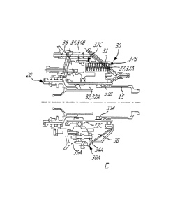
a gearbox, a clutch device, and an output shaft of the gas turbine engine;
[0010] Fig. 2B is an enlarged cross-sectional view of the highlighted
portion of Fig.
2A, the clutch device being shown in a second position;
[0011] Fig, 2C is an enlarged cross-sectional view of the highlighted
portion of Fig.
2A, the clutch device being shown in a first position;
[0012] Fig. 3 is a perspective view of a casing for the clutch device of
the gas
turbine engine of Fig. 1;
2
CA 2992076 2018-01-16
[0013] Fig. 4A is a perspective view of a piston for the clutch device
of the gas
turbine engine of Fig. 1;
[0014] Fig. 4B is a perspective view of a clutch cover for the clutch
device of the
gas turbine engine of Fig. 1;
[0015] Fig. 5 is an exploded perspective view of a sliding coupling for
the clutch
device of the gas turbine engine of Fig. 1, being shown with couplings for the
gearbox
and the output shaft; and
[0016] Fig. 6 is a perspective view of the clutch device of the gas
turbine engine of
Fig. 1 in partial cross-section.
DETAILED DESCRIPTION
[0017] Fig. 1 illustrates a turboprop gas turbine engine 10 of a type
preferably
provided for use in subsonic flight, generally comprising in serial flow
communication an
intake 12 through which air is drawn, a compressor section 14 for pressurizing
the air, a
combustor 16 in which the compressed air is mixed with fuel and ignited for
generating
an annular stream of hot combustion gases, and a turbine section 18 for
extracting
energy from the combustion gases. A power turbine shaft 15 connected to one or
more
turbine(s) of the turbines section 18 projects forwardly to transmit a driving
force to an
output shaft 19 including a propeller 21 via a reduction gearbox generally
shown at 20.
The turbomachinery of the gas turbine engine 10 rotates about a longitudinal
center
axis 11.
[0018] The engine 10 includes a clutch device 30 disposed between the
reduction
gearbox 20 and the power turbine shaft 15. The clutch device 30 is configured
to
selectively couple an output shaft, which in the embodiment of Fig. 1 is the
power
turbine shaft 15, to a gearbox, which is shown as the reduction gearbox 20.
The clutch
device 30 is therefore configured to establish a mechanical link between the
power
turbine shaft 15 and the reduction gearbox 20, and is also configured to break
the
mechanical link between these components of the gas turbine engine 10.
3
=
CA 2992076 2018-01-16
[0019] In the illustrated embodiment, the clutch device 30 is a separate
component
from both the power turbine shaft 15 and the reduction gearbox 20. More
particularly,
the clutch device 30 is "modular in that it can be a self-contained unit
mounted to
different types of gas turbine engines 10 between the turbomachinery of the
gas turbine
engine 10 (an output of which includes the power turbine shaft 15) and the
reduction
gearbox 20. In the depicted embodiment, the clutch device 30 does not affect
the
configuration or components of either the reduction gearbox 20 or the power
turbine
shaft 15, these components remaining substantially unchanged whether the
clutch
device 30 is installed between them or not. In the depicted embodiment, in
which the
gas turbine engine 10 is a "reverse-flow" engine, the clutch device 30 is
disposed aft or
rearward of the gearbox 20 and forward of the power turbine shaft 15. The
forward
direction is defined as being along the direction of travel D of gases through
the gas
turbine engine 10, and the rearward direction is opposite to the direction of
travel D. It
will be appreciated that the clutch device 30 can be positioned elsewhere in
the
depicted gas turbine engine 10, and in other gas turbine engines 10.
[0020] Referring to Fig. 2A, the clutch device 30 mechanically couples,
either
directly or indirectly, the power turbine shaft 15 of the gas turbine engine
10 to the
gearbox 20. When installed, one or more components of the clutch device 30 are
continuously mechanically coupled to one or more components of the gearbox 20.
In
contrast, the clutch device 30 or components thereof selectively engage and
disengage
the power turbine shaft 15. Through this selective engagement with the power
turbine
shaft 15, the clutch device 30 allows the rotational output or drive of the
power turbine
shaft 15 to drive the gearbox 20, and also allows the power turbine shaft 15
to operate
independently of the gearbox 20. The operation of the clutch device 30 can
also be
controlled by a suitable controller as a function of many parameters, such as
engine
operating mode.
[0021] In the embodiment of Fig. 2A, the clutch device 30 includes a
clutch housing
30A. The clutch housing 30A is composed of a single component or multiple
components. The clutch housing 30A or a portion thereof is fixedly mounted to
a casing
of the gas turbine engine. The clutch housing 30A includes a clutch cover 31.
In the
depicted embodiment, the clutch cover 31 is an annular body having an inner
passage
4
CA 2992076 2018-01-16
for receiving therein the power turbine shaft 15 and an input shaft 22 of the
gearbox 20.
At least one embodiment of the clutch cover 31 is described in greater detail
below.
[0022] The clutch device 30 also includes a sliding coupling 32 mounted
to the
engine 10 or a component thereof. In the embodiment of Fig. 2A, the sliding
coupling 32
is mounted to the clutch housing 30A. More particularly, the sliding coupling
32 is
mounted to the clutch cover 31. In alternate embodiments, the sliding coupling
32 is
mounted to other components of the engine 10. The sliding coupling 32 is
continuously
engaged with the input shaft 22 of the gearbox 20 such that the sliding
coupling 32 is
always rotatably coupled to the input gear of the gearbox 20. Conversely, the
sliding
coupling 32 is selectively engaged with the power turbine shaft 15. The
sliding coupling
32 is therefore disposed between the gearbox 20 and the power turbine shaft
15, such
that rotational drive from the power turbine shaft 15 passes through the
sliding coupling
32 and then to the gearbox 20. The sliding coupling 32 can thus take any
suitable
configuration to achieve the above-described functionality. For example, in
the
embodiment shown in Fig. 2A, the sliding coupling 32 is a rotating component.
More
particularly, the sliding coupling 32 is a hollow shaft 32A that is co-axial
with the power
turbine shaft 15 and with the input shaft 22 of the gearbox 20. In some engine
operating
modes, the hollow shaft coupling 32A transmits rotational drive from the power
turbine
shaft 15 to the input shaft 22. The sliding coupling 32 is housed within the
clutch cover
31 and mounted thereto to allow relative sliding movement between the sliding
coupling
32 and the clutch cover 31. In the embodiment shown in Fig. 2A, bearings 32B
support
the sliding coupling 32 and allow its sliding displacement. Other mounting
configurations for the sliding coupling 32 are possible.
[0023] The sliding coupling 32 is selectively engageable with the power
turbine
shaft 15 to mechanically couple the power turbine shaft 15 to the gearbox 20,
and thus
to mechanically couple the gearbox 20 to the turbomachinery of the gas turbine
engine
10. This selective engagement is achieved by sliding the sliding coupling 32
toward the
power turbine shaft 15 to engage it, and by sliding the sliding coupling 32
away from the
power turbine shaft 15 to disengage. In the depicted embodiment, the sliding
coupling
32 is mounted aft of the gearbox 20 and forward of the power turbine shaft 15.
The
sliding coupling 32 therefore slides in an aft or rearward direction R to
engage the
CA 2992076 2018-01-16
power turbine shaft 15, and slides in an opposite, forward direction F to
disengage from
the power turbine shaft 15.
[0024] The sliding coupling 32 is therefore displaceable between a first
position and
a second position, both of which are now described. In the first position, an
example of
which is shown in Fig. 2B, the sliding coupling 32 is mechanically coupled,
directly or
indirectly, to the power turbine shaft 15 to transmit a rotational drive of
the power
turbine shaft 15 to the gearbox 20. To maintain the continuous coupling
between the
sliding coupling 32 and the gearbox 20, the input shaft 22 of the gearbox 20
may also
slide with the sliding coupling 32 in the same direction. In an alternate
embodiment, the
input shaft 22 remains stationary, such that the sliding coupling 32 is the
only
component of the input shaft 22 and the power turbine shaft 15 that undergoes
axial
displacement. In such an embodiment, the meshing portions of the input shaft
22 and
the sliding coupling 32 overlap one another over the entire displacement range
of the
sliding coupling 32, such that the input shaft 22 remains continuously engaged
to the
sliding coupling 32. Such an embodiment is described in greater detail below.
[0025] The mechanical coupling of the sliding coupling 32 to the power
turbine shaft
15 and to the input shaft 22 of the gearbox 20 is shown in Figs. 2B and 2C.
One of the
sliding coupling 32 and the power turbine shaft 15 includes one or more spline
segments 33A. The spline segment 33A is selectively engageable with
corresponding
grooves 33B in the other of the sliding coupling 32 and the power turbine
shaft 15. In
the depicted embodiment, the spline segment 33A is disposed on the power
turbine
shaft 15 and the corresponding grooves 33B are disposed on the sliding
coupling 32,
and it will be appreciated that this configuration can be reversed. Figs. 2B
and 2C show
that the sliding coupling 32 and the input shaft 22 of the gearbox 20 have a
spline/groove configuration as well. Using a spline/groove configuration helps
to reduce
the overall size of the clutch device 10, allowing it to remain compact
particular when
compared to the coupling arrangements of some conventional clutches which rely
on
relative large cone friction pads or cone clutches.
[0026] In the second position, an example of which is shown in Fig. 2C,
the sliding
coupling 32 is disengaged from the power turbine shaft 15. There is therefore
no
mechanical connection between the power turbine shaft 15 and the gearbox 20,
which
6
CA 2992076 2018-01-16
prevents the rotational drive of the power turbine shaft 15 from being
transmitted to the
gearbox 20. The power turbine shaft 15 is therefore free to operate
independently of the
gearbox 20. In an embodiment, the second position of the sliding coupling 32
is
selected during ground operation of the gas turbine engine 10. Since the power
turbine
shaft 15 is freed from having to drive an input gear of the gearbox 20 in the
second
position of the clutch device 30, the rotational drive provided by the power
turbine shaft
15 can be used for other purposes. For example, the rotational drive provided
by the
power turbine shaft 15 can be used as, or coupled to, a generator which
absorbs the
rotational input in order to generate electrical power. Another possible use
for the
decoupled rotational drive of the power turbine shaft 15 is to drive a cabin
air
compressor (CAC), which provides air to the cabin of an aircraft.
[0027] During ground operating mode, an auxiliary power unit (APU)
generally
provides the following: a source of electrical power to the aircraft, a source
of pneumatic
power for cabin air. The APU typically provides this functionality with its
own
accessories. It will be therefore appreciated that the clutch device 30, by
decoupling the
gearbox 20 from the turbomachinery of the gas turbine engine 10, allows the
decoupled
power turbine shaft 15 to provide these services instead, so as to eliminate
the need for
a separate APU and its redundant accessories, added complexity, maintenance,
emissions, and noise. In this regard, it should be noted that many airports
around the
world have limited the amount of time that APUs can be used prior to
departure, or
have prohibited their use outright.
[0028] In substantially all of the engine operating modes other than
ground
operating mode, the turbomachinery is operating most efficiently. During these
engine
operating modes (e.g. flight operating mode), the clutch device 30 couples the
gearbox
20 to the power turbine shaft 15. The clutch device 30 therefore allows the
turbomachinery of the gas turbine engine 10 to drive the gearbox 20 during
operating
modes of the gas turbine engine 10 where it is more efficient to do so. In an
embodiment, these more efficient engine operating modes include all operating
modes
except ground engine operating mode. In such an embodiment, the ground
operating
mode is a unique engine operating mode. It will be appreciated that for
applications in
which two or more gas turbine engines 10 work in concert (e.g. in a multi-
engine
7
CA 2992076 2018-01-16
aircraft), the clutch device 30 can be provided for only one of the gas
turbine engines
10.
[0029] Still referring to Figs. 2B and 2C, the clutch device 30 also
includes a piston
34 for slidingly displacing the sliding coupling 32. The piston 34 is disposed
within the
clutch housing 30A and mounted thereto. The piston 34 displaces in a linear
fashion
with respect to the clutch cover 31. The piston 34 is also mounted to the
sliding
coupling 32. In the depicted embodiment, there is no relative movement between
the
piston 34 and the sliding coupling 32. The piston 34 and the sliding coupling
32 are
therefore displaced together. A bearing 34A supports the rotating sliding
coupling 32
with respect to the non-rotating piston 34. When the piston 34 and the bearing
34A are
displaced in the aft or rearward direction R, the bearing 34A slides along an
outer
surface of the sliding coupling 32 until it abuts against a flange 32C on the
outer surface
of the sliding coupling 32. The bearing 34A exerts a pressure against the
flange 320,
causing the flange 320 and the sliding coupling 32 to slidingly displace with
the piston
34 in the direction R. Other mounting configurations between the piston 34 and
the
sliding coupling 32 which achieve the above-described sliding displacement of
the
sliding coupling 32 are possible and within the scope of the present
disclosure.
[0030] The piston 34 slidingly displaces the sliding coupling 32 to at
least the
second position shown in Fig. 20. It is meant by "at least the second
position" that the
piston 34 in operation displaces the sliding coupling 32 into its second
position to
disengage the clutch device 30 from the power turbine shaft 15, and may in
some
instances also displace the sliding coupling 32 to the first position. This is
the case in an
embodiment where the piston 34 actively exerts a force to both slide the
sliding
coupling 32 to the second position, and to slide the sliding coupling 32 to
the first
position.
[0031] In the embodiment shown in Figs. 2B and 20, the piston 34 applies
a force
to slide the sliding coupling 32 only to the second position, and does not
apply a force
to slide the sliding coupling 32 to the first position. The force supplied by
the piston 34 is
generated with hydraulic fluid whose pressure builds up within a hydraulic
fluid cavity.
The clutch housing 30A also includes an annular casing 35 separate from and
mounted
to the clutch cover 31. An annular hydraulic fluid cavity 36 is formed between
the casing
8
CA 2992076 2018-01-16
35 and the clutch cover 31. The piston 34 in the embodiment shown in Figs. 2A
and 2B
includes a hydraulic piston 34B. The hydraulic piston 34B is actuated by
hydraulic fluid
and is disposed within the fluid cavity 36 to be displaced therein. When the
fluid cavity
36 is filled with hydraulic fluid, the pressure of the hydraulic fluid within
the fluid cavity
36 increases, and exerts a pressure against the head of the hydraulic piston
34B. This
causes the hydraulic piston 34B to displace in the rearward direction R, and
therefore
displaces the attached sliding coupling 32 to the second position. The casing
35 has
one or more bleed holes 35A in fluid communication with the fluid cavity 36 to
drain
hydraulic fluid from the fluid cavity 36. In an alternate embodiment, the
bleed holes 35A
are part of the clutch cover 31. When the fluid cavity 36 is drained of the
hydraulic fluid
via the bleed holes 35A, the hydraulic pressure acting against the head of the
hydraulic
piston 34B is reduced. The hydraulic piston 34B therefore no longer applies a
force
against the sliding coupling 32. The hydraulic piston 34B can therefore be
displaced
from the second position to thereby move the sliding coupling 32 to the first
position, as
explained in greater detail below.
[0032] Still referring to Figs. 2B and 2C, once the piston 34 has
displaced the
sliding coupling 32 to the second position, the piston 34 stops applying a
force on the
sliding coupling 32, and the sliding coupling 32 is instead displaced in the
direction of
the first position with one or more biasing members 37. The biasing member 37
shown
in Figs. 2B and 2C is a torsional spring 37A, and it will be appreciated that
other biasing
members 37 are within the scope of the present disclosure. In other
embodiments, one
or more of the biasing members 37 include a helical coil spring, a leaf
spring, and a
cantilever spring, to set forth just a few non-limiting examples of devices
capable of
storing and releasing energy. Similarly, the number of biasing members 37 can
vary,
and they can be disposed at equal or unequal circumferential intervals about
the
annular clutch cover 31.
[0033] The biasing members 37 in operation apply a biasing force to the
piston 34
to return the piston 34, and thus the sliding coupling 32 mounted thereto, to
the first
position shown in Fig. 2B. In an alternate embodiment, one or more of the
biasing
members 37 engage the sliding coupling 32 directly. In the depicted
embodiment, a first
end 37B of each biasing member 37 is mounted to the clutch cover 31, and an
opposite
9
CA 2992076 2018-01-16
second end 370 is mounted to the piston 34. When the piston 34 is deactivated
such
that it no longer applies sufficient force to displace the sliding coupling 32
to the second
position, the biasing members 37 expand to apply a biasing force (e.g. a
spring force) to
displace the piston 34 and the sliding coupling 32 to the first position. When
the piston
34 is activated to displace the sliding coupling 32 to the second position,
the
displacement of the piston 34 in direction R compresses the biasing members 37
such
that the piston 34 works against the spring force of the biasing members 37.
In this
embodiment, where the piston 34 is operable to displace the sliding coupling
32 only to
the second position, the default position of the sliding coupling 32 is the
first position.
Stated differently, the position in which the sliding coupling 32 finds itself
for almost all
engine operating modes is the first position in which the gearbox 20 is
mechanically
coupled to the power turbine shaft 15.
[0034] In the particular embodiment shown in Figs. 2B and 20, the
biasing
members 37 cooperate with the hydraulic piston 34B as follows. In order to
disengage
the sliding coupling 32 from the power turbine shaft 15 and thus disengage the
gearbox
20 from the turbomachinery as shown in Fig. 20, hydraulic fluid is pumped into
the fluid
cavity 36 to increase the fluid pressure therein and displace the hydraulic
piston 34B.
The hydraulic piston 34B is therefore displaced and displaces with it the
sliding coupling
32 to disengage it from the power turbine shaft 15. The displacement of the
hydraulic
piston 34B works against the biasing members 37 by compressing them. In order
to
engage the sliding coupling 32 with the power turbine shaft 15 and thus engage
the
gearbox 20 with the turbomachinery as shown in Fig. 2A, no hydraulic fluid is
supplied
to the fluid cavity 36. Without a supply of hydraulic fluid, the hydraulic
fluid within the
fluid cavity 36 drains out via the bleed holes 35A. Without fluid pressure
acting against
the hydraulic piston 34B, the biasing members 37 extend and exert a biasing
force
against the hydraulic piston 34B. This causes the hydraulic piston 34B and the
sliding
coupling 32 mounted thereto to displace in the forward direction F to the
first position
where it is engaged with the power turbine shaft 15.
[0035] Still referring to Figs. 2B and 20, the clutch device 30 includes
one or more
movement limiters 38. Each movement limiter 38 limits the stroke of the piston
34 and
allows adjustment thereof. The piston 34 is therefore configurable to displace
only the
CA 2992076 2018-01-16
amount needed. Each movement limiter 38 extends between the clutch cover 31
and
the piston 34. In the depicted embodiment, each movement limiter 38 is in the
form of a
snubber, and also helps to prevent rotation of the piston 34 caused by its
engagement
with the rotating hollow shaft coupling 32A.
[0036] An embodiment of the casing 35 is shown in Fig. 3. The casing 35
is an
annular body having a central passage 35B for receiving therein the power
turbine shaft
15, the input shaft 22 of the gearbox 20, and the sliding coupling 32. The
hydraulic fluid
cavity 36 is formed between an inner annular body and an outer annular body. A
fluid
input 35C receives hydraulic fluid from an external source and provides it to
the fluid
cavity 36. The one or more bleed holes 35A are in fluid communication with the
fluid
cavity 36 to drain hydraulic fluid from the fluid cavity 36.
[0037] An embodiment of the hydraulic piston 34B is shown in Fig. 4A.
The
hydraulic piston 34B is in the form of an annular disc. A piston head 340 of
the
hydraulic piston 34B has a first surface 340 and an opposite second surface
34E. The
first surface 34D faces the hydraulic fluid in the fluid cavity 36 which
applies pressure
thereagainst. The second surface 34E faces the clutch cover 31 and the biasing
members 37, which apply a biasing force thereagainst. The second surface 34E
therefore has a plurality of landings 34F. Each landing 34F is a portion of
the piston
head 340 that is recessed from the second surface 34E. Each landing 34F
receives
therein the second end 37C of a corresponding biasing member 37. The first and
second surfaces 34D,34E are hydraulically isolated from each other by an
annular
gasket 34G which extends around a peripheral circumference of the piston head
340.
The gasket 34G engages a corresponding surface of the clutch cover 31 to form
a seal
therewith. It will be appreciated that the piston 34 can take other forms. In
an alternate
embodiment, the piston 34 includes one or more self-contained hydraulic
actuators
each with an inner displaceable piston rod which are circumferentially spaced
apart.
Other configurations are also possible.
[0038] An embodiment of the clutch cover 31 is shown in Fig. 4B. The
clutch cover
31 includes multiple flanges 31A with corresponding bolt holes 31B which allow
the
clutch cover 31 to be mounted to the casing 35. The clutch cover 31 is an
annular body
having an inner central passage 310 for receiving therein the power turbine
shaft 15,
11
CA 2992076 2018-01-16
the input shaft 22 of the gearbox 20, and the sliding coupling 32. An inner
circumferential sealing surface 31D helps to define the fluid cavity 36, and
engages with
the gasket 34G of the hydraulic piston 34B to seal part of the clutch cover
31. The
clutch cover 31 has multiple nests 31E for receiving therein the first end 37B
of a
corresponding biasing member 37.
[0039] Figs. 4A and 4B also show an embodiment of the movement limiters
138
which limit the stroke (i.e. displacement) of the piston 34. One or more of
the movement
limiters 138 includes a snubber stop 138A. Each snubber stop 138A is a flange
protruding radially inward from the sealing surface 31D of the clutch cover
31. Each
snubber stop 138A is configured to abut against a surface of the piston 34 to
prevent its
further rearward displacement. Each snubber stop 138A includes a mounting hole
138B
for receiving therein a corresponding displacement rod 138C. Each displacement
rod
138C extends between a first end 138D mounted through a corresponding mounting
hole 138B and a second end 138E mounted through a corresponding hole 138F in
the
second surface 34E of the piston 34. Each displacement rod 1380 allows the
piston 34
to displace therealong and guides displacement thereof. Each displacement rod
1380
also prevents the piston 34 from rotating about the longitudinal center axis
11 of the gas
turbine engine 10. One or more of the displacement rods 138C includes a nut
138G
mounted about a threaded portion of the displacement rod 138C. A portion of
the
second surface 34E of the piston 34 is engageable with each nut 138G to arrest
sliding
displacement (i.e. the stroke) of the piston 34. The position of the nut 138G
on the outer
surface of the displacement rod 1380 is adjustable. By adjusting the position
of the nut
138G on the displacement rod 1380, it is possible to set the stroke for the
piston 34.
[0040] An embodiment of the sliding coupling 32, the input gear 22 of
the gearbox
20, and a coupling 15A of the power turbine shaft 15 is shown in Fig. 5. Each
component is a rotatable cylinder. The coupling 15A of the power turbine shaft
15 has a
splined portion 15B on an outer surface thereof which mates with a
correspondingly
grooved portion along an inner surface of the sliding coupling 32. Similarly,
the input
gear 22 of the gearbox 20 has a splined portion 22A on an outer surface
thereof which
mates with a correspondingly grooved portion 33B along the inner surface of
the sliding
coupling 32. The sliding coupling 32 and the gearbox 20 engage one another and
12
CA 2992076 2018-01-16
overlap along the splined portion 22A and the grooved portion 33B. The grooved
portion 33B of the sliding coupling 32 has a greater axial length than the
splined portion
22A of the input gear 22. More particularly, the axial length of the grooved
portion 33B
is equal to or greater than the stroke of the piston 34. Therefore, as the
sliding coupling
32 slides in the rearward or forward direction R,F relative to the stationary
input gear
22, the grooved portion 33B will remain continuously meshed with the splined
portion
22A. This allows the sliding coupling 32 to remain continuously engaged with
the input
gear 22 of the gearbox 20. The sliding coupling 32 shown in Fig. 5 therefore
is a free
spline coupling having a radially internal spline or grooved portion 33B at
one end
thereof, and a radially internal spline or grooved portion at another end of
the sliding
coupling 32. The ends of the splines and/or grooves can be rounded and have
lead-in
chamfers to allow smooth engagement and disengagement.
[0041] Fig. 6 shows the clutch device 30 with many of the components
described
herein. More particularly, the clutch device 30 shown has an annular casing 35
mounted to the clutch cover 31. The input gear 22 of the gearbox 20, the
sliding
coupling 32, and the power turbine shaft 15 are co-axial with the longitudinal
center axis
11 and disposed within the central passages 31C,35B of the clutch cover 31 and
casing
35, respectively.
[0042] Referring to Fig. 2A, there is also disclosed herein a method of
mounting the
clutch device 30 to the gas turbine engine 10. The method and clutch device 10
disclosed herein can be used to adapt an existing gas turbine engine 10 having
the
gearbox 20 and the output shaft 15 to function as described above. The method
includes positioning the clutch device 30 between the gearbox 30 and the
output shaft
15. The method also includes mechanically and continuously coupling the clutch
device
30 to the gearbox 20. The method also includes coupling the clutch device 30
to the
output shaft 15 to engage the output shaft 15 and transmit a rotational drive
of the
output shaft 15 to the gearbox 20, and to disengage the output shaft 15.
[0043] There is also disclosed herein a method of operating the gas
turbine engine
10. The method includes mechanically coupling the clutch device 30 to the
output shaft
15 during flight operating mode of the gas turbine engine 10. The clutch
device 30 is
continuously mechanically coupled to the gearbox 20. The method also includes
13
CA 2992076 2018-01-16
disengaging the clutch device 30 from the output shaft 15 during ground
operating
mode of the gas turbine engine 10. The ground operating mode (e.g. ground
idle) is a
different operating mode from the flight operating mode of the gas turbine
engine 10.
[0044] Although the clutch device 30 is described herein as selectively
coupling the
power turbine shaft 15 to the reduction gearbox 20, it will be appreciated
that the clutch
device 30 disclosed herein is operable to selectively couple other driven and
drivable
components as well. The clutch device 30 can therefore be used with other
gearboxes
that use their gearing to modulate the rotational drive received from an
output shaft,
such as an offset gearbox. The clutch device 30 can similarly be used with
other output
shafts, which include any suitable mechanical output of the turbomachinery of
the gas
turbine engine 10. Alternatively, the output shaft can be a separate rotating
component
which is itself mechanically linked to a rotating shaft of the turbomachinery.
[0045] The expressions "mechanically linked" or "mechanically coupled"
as used
herein refer to the direct connection, or indirect connection (e.g. via gears
or a
transmission), of components with one another by a suitable mechanical device.
In the
present specification, including claims, the term "engaged" is intended to
include any
engagement allowing two components to rotate together, at the same speed or at
different speeds, and in the same direction or in different directions,
including, but not
limited to, direct connections, direct meshed engagement, engagement through
meshing with one or more intermediate meshed element(s) (gear, pinion, etc.)
and
engagement through intermediate elements, e.g. idler gear.
[0046] The above description is meant to be exemplary only, and one
skilled in the
art will recognize that changes may be made to the embodiments described
without
departing from the scope of the invention disclosed. Still other modifications
which fall
within the scope of the present invention will be apparent to those skilled in
the art, in
light of a review of this disclosure, and such modifications are intended to
fall within the
appended claims.
14
CA 2992076 2018-01-16