Note: Descriptions are shown in the official language in which they were submitted.
POWERED LIQUID SPRAY APPARATUS TO COAT PIPE JOINTS
BACKGROUND
This disclosure is in the field of systems and methods used to apply
protective coatings to
pipe joints.
One process for applying a protective coating to a pipe joint is to use an air
applicator
gun, point it directly at the pipe, and manually spray a two-part epoxy
coating onto the joint.
This manual process is operator-dependent and, as such, does not always apply
the coating
evenly.
Another process eliminates operator-dependency but uses an expensive multi-
component
pumping system in connection with a powered ring that sprays the coating. The
pumping system
requires harsh cleaning materials to clean the nozzles and lines.
SUMMARY
A powered liquid spray apparatus includes a power-driven circumferential ring
that
rotates about a horizontal longitudinal axis coaxial to the power-driven
circumferential ring and
an air gun mounted to the circumferential ring. The air gun includes at least
one nozzle oriented
perpendicular to the horizontal longitudinal axis.
A powered liquid spray apparatus includes an air gun that is mounted to at
least one
bracket and has at least one nozzle oriented in a horizontal lateral
direction, a coating component
in communication with the air gun, means to flow the coating component to the
nozzle in a
controlled manner, and means to move the air gun relative to a horizontal
longitudinal direction.
A method for coating a pipe joint includes mounting an air gun with a nozzle
to a
powered circumferential ring so that the nozzle is oriented perpendicular to
the horizontal
1
=
CA 2992472 2018-01-22
longitudinal axis of the ring, rotating the powered circumferential ring about
the pipe joint, and
flowing coating in a controlled manner through the nozzle.
BRIEF DESCRIPTION OF THE DRAWINGS
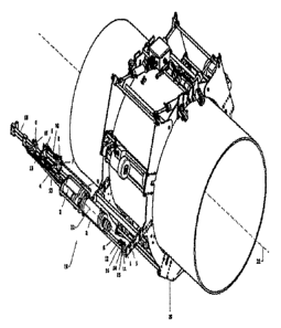
FIG. 1 is an isometric view of an embodiment of a powered liquid spray
apparatus.
FIG. 2 is a front elevation view of the embodiment of FIG. 1.
FIG. 3 is a top plan view of the embodiment of FIG. 1.
FIG. 4 is a side elevation view of the embodiment of FIG. 1.
FIG. 5 is front elevation view of an embodiment in which the air gun is
mounted
perpendicular to the pipe's central longitudinal axis.
FIG. 6 is an isometric view of the embodiment of FIG. 5.
Elements and Numberim_., Used in the Drawings
Cap screw
2 Cylinder assembly
3 Ratio pack
4 Larger static mixer
5 Spray gun bracket
6 Applicator mounting bar
7 Smaller static mixer
8 Nozzle
9 Spray tube
10 Nozzle mount
11 Elbow
2
CA 2992472 2018-01-22
12 Connector
13 Elbow
14 U-bolt
15 Plate
16 Ball valve
17 Support arm bracket
18 Nozzle support
19 Air gun
20 Power-driven circumferential ring
21 Central longitudinal axis of pipe and power-driven circumferential ring
22 Longitudinal axis of mounted air gun
DETAILED DESCRIPTION
This application incorporates by reference the subject matter of U.S.
Provisional Patent
Application No. 62/450,120, filed January 25, 2017.
As shown in FIGS. 1-6, an embodiment of a powered liquid spray apparatus to
coat pipe
joints mounts a modified air-regulated air gun to a power-driven
circumferential ring 20 located
about the pipe so that the longitudinal axis 22 of the mounted air gun 19 runs
parallel or
perpendicular (normal) to the central longitudinal axis 21 of the pipe and
ring 20 but sprays the
coating perpendicular to the pipe. The air gun 19 may be held in a fixed
relationship to the pipe
or may include a reciprocating head that moves the gun 19 back-and-forth in an
axial direction
while spraying.
The air gun 19 may be equipped with a plural component ratio pack 3 which
contains at
least one cylinder or tube of epoxy and a 90 applicator tip or nozzle 8.
Multiple cylinders of
3
CA 2992472 2018-01-22
epoxy may be connected to the same nozzle 8. Alternatively, the ratio pack 3
may contain a
plurality of nozzles 8, with each nozzle 8 connected to its own cylinder of
epoxy or to a cylinder
of epoxy that is shared with at least one other nozzle 8. For example, the
ratio pack 3 may have
three nozzles 8 and three cylinders of epoxy in a one-to-one ratio.
The power-driven circumferential ring 20 may be an electrically driven PCSTM
powder
ring (Pipeline Coating Services, Conroe, Texas) or its equivalent, including
hydraulic or
pneumatic driven rings. The air gun 19 may be a modified version of the air
guns found in U.S
Patent No. 5,197,635, U.S. Patent No. 6,290,101 or their equivalent, including
but not limited to
air guns supplied by Albion Engineering Company, Sulzer Mixpac USA (COXTm),
Sulzer
Mixpac Denmark A/S (Kroger A/S), Wellmade Tool, and Newborn Brothers Co., Inc.
The air
gun 19 may also be a battery operated gun, including but not limited to those
provided by Albion
Engineering Company and Meritool LLC. The air gun 19 is modified by removing
the trigger
and built-in metering valve (if any) and adding an optional cap. A split band
may be used to help
support the gun 19 in its required parallel orientation.
The flow rate of coating through the air gun 19 and onto the pipe is
controlled so that the
flow is in a state of statistical process control. The flow is controlled with
an externally mounted
air regulator (not shown) arranged to provide a consistent force on the air
gun's internal piston(s)
or plunger(s). This consistent force results in a constant, predictable flow
rate of coating, leading
to a properly applied coating. Alternatively, a reciprocating force may be
applied. The
reciprocating flow rate is again controlled so that the flow rate is in a
state of statistical process
control.
The nozzle 8 applies the coating perpendicular to the pipe in close proximity
to the pipe
joint being coated. When the air gun 19 is mounted in a parallel orientation,
the pipe can be
4
CA 2992472 2018-01-22
skid-mounted and remain close to the ground during the coating operation.
Because of one-time
use material packaging, inherent to the air applicator gun style used, labor-
intensive and harsh
cleaning intensive clean-up is not required. Also, by automating the coating
process, operator
workload and exposure to the coating materials are reduced.
While the disclosure may be susceptible to various modifications and
alternative forms,
specific embodiments have been shown by way of example in the drawings and
described. This
disclosure is not intended to be limited to the particular embodiments
disclosed. Rather, the
disclosure is to cover all modifications, equivalents, and alternatives
falling within the scope of
the disclosure as defined by the following claims.
5
CA 2992472 2018-01-22