Note: Descriptions are shown in the official language in which they were submitted.
INVESTMENT MOLD SLURRY CURTAIN APPARATUS
CROSS-REFERENCE TO RELATED APPLICATIONS
[0001] This application claims priority of US application no. 62/240,727,
filed on
October 13, 2015.
FIELD OF THE INVENTION
[0002] The subject invention relates generally to an investment mold slurry
curtain
apparatus, and in an embodiment may be described as an investment mold slurry
coating
apparatus.
BACKGROUND
[0003] The investment casting industry requires the use of suitable investment
casting
molds. Preferably, these investment casting molds will accurately and
precisely reflect the final
features and dimensions of the desired cast part as closely as possible,
thereby avoiding the need
for additional machining or finishing operations to achieve the desired
component or part. These
investment casting molds, particularly countergravity investment casting
molds, utilize pattern
assemblies of the articles to be cast that are formed from a fugitive or
removable material. These
pattern assemblies arc invested with a refractory particulate material to form
a refractory shell.
[0004] Investment casting pattern assemblies, particularly those used for
countergravity
investment casting, have generally been formed by attaching one or more mold
patterns of the
article or articles to be formed to a central sprue pattern that extends along
a sprue axis. The
mold patterns are generally connected to the central sprue by a radially
extending gate pattern or
a plurality of gate patterns. Once a pattern assembly has been coated with a
refractory shell, the
fugitive material is removed to define a refractory mold assembly that
includes a central sprue, a
plurality of radially extending gates, and associated mold cavities that
define passageways or
conduits within the refractory mold for the purpose of feeding molten metal
into the mold
cavities, where it is solidified to form the desired cast articles.
1
CA 2992604 2019-07-31
CA 02992604 2018-01-15
WO 2017/066374
PCT1US2016/056728
100051 Generally, refractory molds are made by orienting the pattern assembly
with the sprue pattern oriented substantially vertically and dipping the
pattern
assembly of the fugitive material into a slurry bath ofa refractory slurry
material that
includes a liquid, binder and refractory particles. The pattern assembly is
Men
removed from the slurry bath producing a wet slurry coating on the outer
surface of
the pattern assembly. The wet slurry coating may then be coated with a layer
of
refractory stucco particles, such as by dipping the wet coating layer into a
fluidized
bed of stucco particles, and then dried to provide a dried layer of refractory
particles
from the slurry and refractory stucco particles. This process is generally
repeated to
form a plurality of dried layers of refractory particles and refractory stucco
particles.
The fugitive material is then removed from the refractory shell forming the
refractory
investment casting mold assembly. These refractory casting mold assemblies are
then
used for investment casting of various molten metals and alloys having a shape
defined by the pattern assemblies of the fugitive Materials. While this method
is
useful and has been used extensively in the past, it is a time consuming batch
process.
The conventional steps of dipping, stuccoing, and drying are done
discontinuously as
batch processes, generally using different equipments located in different
rooms or
portions of a facility, including a slurry bath, a stucco particle sander, and
a drying
room or oven. The method requires extensive handling of the pattern
assemblies,
including transfer to the various batch stations described .for implementation
of the
steps,as well as repetition of the steps needed to produce a plurality of
layers of
refractory particles and refractory stucco particles sufficient to define a
refractory
mold. The method generally takes a minimum of several days to a week or more
to
produce a refractory mold assembly using the apparatus mentioned,
SUMMARY OF THE INVENTION
100001 To-overcome the shortcomings of the conventional investment casting
mold making processes, improved apparatuses and methods for making refractory
molds for investment casting are very desirable, particularly methods and
apparatuses
that reduce the time needed-to-produce a refractory mold assembly.
1100071 In one exemplary embodiment, an investment mold slurry curtain
apparatus is disclosed, The Slurry curtain apparatus includes a slurry curtain
of a
slurry fluid, the slurry curtain having a length and a thickness, the length
substantially
CA 02992604 2018-01-15
WO 2017/066374
PCT1US2016/056728
greater than the thickness. The apparatus also includes an outlet configured
to
dispense the slurry fluid and form the slimy curtain.
[00081 In another exemplary embodiment, the investment mold slurry curtain
apparatus may include and be described as an investment mold slurry coating
apparatus. The investment moldy slurry coating apparants includes a conduit
configured to receive a flow of a slurry fluid. and an outlet operatively
couple to the
conduit, the outlet configured to dispense the flow of the slurry as a curtain
of the
slurry.
[00091 The above features and advantages and other features and advantages
of the invention are readily apparent from the following detailed description
of the
invention when taken in connection with the accompany* drawings.
BRIEF DESCRIPTION OF THE DRAWINGS
100101 Other features, advantages and details appear, by way of-example only,
itythe following detailed description of embodiments, the detailed
description.
referring to the drawings in which:
100111 'FIG. 1 is a cross-sectional view of an embodiment of a slurry curtain
apparatus 10 as disclosed herein;
(001.21 FIG. IA is a cross-sectional view of the embodiment of FIG. 1 taken
along section A-A;
[00131 FIG. 2 is a cross-sectional view of another embodiment of a slurry
curtain apparatus 10 as disclosed herein;
[00141 FIG. 3 is a bottom view of another embodiment of a slurry curtain
apparatus 10 as disclosed. herein;
[00151 FIG. 4 is a bottom view of yet another embodiment of a Slurry cumin
apparatus 10 as disclosed herein showing a partial section of a slurry
curtain;
100161 FIG. 5 is a bottom view of still another embodiment of a slurry curtain
apparatus 10 as disclosed herein showing a partial section of a slurry
curtain;
(00171FIG. 6 is a bottom view of a further embodiment of a slurry curtain
apparatus 10 as disclosed herein showing a partial section of a slurry
curtain;
[00181 FIG. 7 is a schematic illustration of an embodiment of slurry coating
apparatus 100 and slurry curtain as disclosed herein;
3
CA 02992604 2018-01-15
WO 2017/066374
PCT1US2016/056728
100191 FIG. -8 is a bottom view of the embodiment of FIG. 7;
[0020] FIG. 8B is a cross-sectional view of the embodiment of FIG. 8 taken
along section B-B;
[0021] FIG. 9 is a bottom view of another embodiment of slurry coating
apparatus 100 and Slurry curtain as disclosed herein;
[00221 FIG. 10 is a front View of the embodiment of FIG. 9;
[0023] FIG. 11 is a front view of another embodiment of slurry coating
apparatus 100 h.:chiding-a plurality of conduits and slurry curtain as
disclosed herein;
[00241 FIG. 1.2.is a schematic illustration of an embodiment of slurry coating
apparatus 100 and conduits 30 spaced circumferentially abouta removable mold
pattern assembly;
(0025114G. 13A, 13B, and 13C are top, front, and side views, respectively, of
an embodiment of slurry coating apparatus 100 and conduit 30 with an end
nozzle 46
as describtxl herein;
l0026I FIG. 14A and 14B are front and bottom views, respectively, of an
embodiment of slurry coating apparatus 100 and conduit. 30 with an nozzle 46
along
the length as described herein;
100271 FIG. 15 is a cross-sectional view of another embodiment of slurry
coating apparatus 100 along the length of conduit 30 with an insert 68 as
disclosed
herein;
100281 FIG. 16 is a lateral cross-sectional view of another embodiment of
stuny coating apparatus 100. and conduit 30 with an chamber 69 as disclosed
herein;
[0029] .FIG. 17A-17C are a top, side, and cross-sectional view along section
C¨C, respectively, of an embodiment of slurry coating manifold apparatus 200
as
disclosed herein;
(003(1 FIG 18A-1 8B are a top and side view of another embodiment of slurry
coating manifold apparatus 200 as disclosed herein;
4
CA 02992604 2018-01-15
WO 2017/066374
PCT1US2016/056728
100311 FIG. 19 is a partial cross-sectional view of another embodiment of
slurry coating manifold apparatus 200 and side opening 222 as disclosed
herein;
[00321 FIG. 20 is a partial cross-sectional view of another embodiment of
slurry coating manifold apparatus .200 and top opening 216 as disclosed
herein;
100331 FIG. 21 is. a top view of another embodiment of Slurry coating
manifold apparatus 200 and parallel connection of manifolds as disclosed
herein;
[00341 FIG. 22 is .a top view of another embodiment of slurry coating
manifold apparatus 200 and serial cotmectiOn of manifolds as disclosed herein;
100351 FIG. 23 is a schematic cross-sectional view of an embodiment of an
investment mold pattern assembly 302 as described herein;
100361 FI0.-24 is a schematic cross-sectional view of an embodiment of an
investment mold pattern assembly 302 as described herein;
100371 FIG. 25 is a perspective view of an embodiment of an investment mold
making apparatus 300 as described herein;
[0038] FIG..2513 is an enlargement of a portion of region D of FIG. 25;
100391 FIG. 26 is a cross-sectional, view of an embodiment of a shell mold
build and accumulated coating layers therein;
[00401 FIG. 27 is a perspective view of an embodiment of a mandrel as
disclosed herein;
1:0041] FIG. 28 is a perspective view of an embodiment of a mandrel support
member as disclosed herein;
100421 -FIG. 29 is a perspective view of an embodiment of a slurry coating
station. as described herein;
(0043) FIG. 30 is a perspective view of an embodiment of a stucco coating
station as described herein;
(0044) FIG. 31 is a schematic illustration of an embodiment of an investment
mold making apparatus 300 as described herein;
CA 02992604 2018-01-15
WO 2017/066374
PCT1US2016/056728
[0045] FIG. 32 is a schematic illustration of an embodiment of an alternate
investment Mold making apparatus 300' as described herein;
100461 .F1G$, 33A and 338 are schematic illustrations of embodiments of a
conveyor for use in a workstation, including a stucco coating station as
described
herein;
[00471 FIGS 34 A and 348 are schematic illustrations- of embodiments of a
stucco coating station as described herein;
[0048] FIG. 35 is a flowchart of a -method of making a refractory mold as
disclosed herein;
[00491 FIG.36 is a perspective view of an embodiment of a slurry coating
station 320 and slurry manifold 210 as disclosed herein;
No50.) FIG. 37 is a schematic illustration of an embodiment of a stucco
coating station 330 and slurry manifold as disclosed herein; and
(00511 FIG. 38 is a schematic illustration of an embodiment of a drying
station 340 and drying jets as disclosed herein.
DESCRIPTION OF THE 'EMBODIMENTS
[00521 Referring to the figures, including FIGS. 1-38, a method and
apparatuses for making a refractory investment casting mold assembly are
described.
These apparatuses include an investment mold slurry curtain apparatus 10 as
shown in
FIGS. 1, IA and 2. In one embodiment, the investment mold slurry curtain
apparatus
IQ is included in aninvestment mold slurry coating apparatus 100 as shown in,
for
example, FIGS. 7-16. in another embodiment, the investment mold slurry curtain
apparatus 10 is included in an investment mold slurry coating manifold
apparatus 200
as shown in FIGS. 17/V22. The investment mold slurry curtain apparatus 10 in
the
embodiments described is very advantageous because it enables application of a
wet
slurry coating of refractory particles onto a fugitive pattern assembly in a
new way
that is very different from dipping using conventional slurry baths as
described above.
The investment mold slurry curtain imparatus 10 is particu lady advantageous
for a
number of reasons described herein, and particularly because the apparatus can
readily be integrated into an apparatus or system that provides continuous
manufacture of refractory investment mold assemblies.
6
CA 02992604 2018-01-15
WO 2017/066374
PCT1US2016/056728
100531 These apparatuses also include an investment mold making apparatus
300 that includes an investment mold slurry curtain apparatus 10 integrated
together
with other devices necessary to manufacture refractory investment casting mold
assemblies as shown in FIGS. 25-34B. The integration of these devices
advantageously provides an apparatus or system that enables the continuous or
semi-
continuous manufacture of refractory investment casting mold assemblies,
greatly
reducing the manufacturing time needed to produce these assemblies and the
associated manufacturing cost, as well as improving the quality and
repeatability of
the assemblies produced. As is readily understood by those of ordinary skill
in the
art, the ability to reduce the cost and cycle time needed to manufacture the
refractory
mold assemblies directly reduces the cost of the investment castings made
using these
molds, both with regard to the mold costs, as well as increased throughput of
finished
castings
100541 The investment mold slurry curtain apparatus 10 and investment mold
making apparatus 300 enable and can be used to practice a method 400 of making
refractory shell mold assemblies as shown in FIG. 35, The apparatuses 10, 100,
200,
and 300 provide for rotatable and/or substantially horizontal orientation of
the
longitudinal or sprue axis of the pattern-assembly during the coating proems
and
incorporation of a slurry curtain, such as an axially extending slurry
curtain, to apply
the slurry coating rather than dip coating. The use of the rotatable and/or
substantially
horizontal orientation of the pattern assembly together with the slurry
curtain enables
the use of various conveyor devices 80 and. factory automation devices and
implementation of a continuous, or semi-continuous or partially continuous,
method
400 of making refractory shell mold assemblies 600. The continuous method 400
is
very advantageous because it greatly reduces the time required to build a
refractory
shell mold assembly 60() and the associated cost of the assembly. The method
400
also advantageously offers new methods of handling and storing the coated
pattern
assemblies in their rotatable horizontal orientation both during and in-
between the
various elements of the refractory shell mold assembly process. For example,
after
applying the slurry coating, the wet coated pattern assemblies can continue to
be
rotated at a predetermined rotational rate or speed, Which may be a constant
speed or a
variable speed or a combination thereof, as they drain and move through the
subsequent elements of the method 400 to ensure the uniformity of the
resultant
7
CA 02992604 2018-01-15
WO 2017/066374
PCTIUS2016/056728
coating. The horizontal orientation also enables flexible stacking and storage
of the
coated pattern assemblies as they progress through the elements of the method
400 or
afterward in all manner of stacking and storage devices or equipment,
including
without limitation, vertically oriented racks, horizontally oriented racks,
serpentine. or
other circuitous conveyors, and horizontal or vertical carousels that can
easily be
integrated into a conveyor device or system. Having generally described the
invention and some of the associated advantages, a detailed description
follows
below,
Investment Mold Slurry Curtain Apparatus
(00551 Referring to FIGS. I and 1A, an investment mold slurry curtain
apparatus 10 includes a slurry curtain 12 of a slurry fluid 14. Investment
shell molds
are made by applying a series of ceramic coatings to pattern assemblies or
pattern
clusters. Each coating may include a coating layer 16. The coating layer 16
may be
formed by applying the slurry curtain 12 via the slurty fluid 14. The slurry
fluid 14
includes a refractory slurry fluid. suitable for providing a wet coating layer
16 of
refractory particles on a fuaitive or removable mold pattern assembly I& The
refractory slurry .fluid 14 may include any suitable constituents for making
the
coating. in one embodiment, refractory slurry fluid 14 includes a plurality of
refractory particles, a binder, and a liquid or fluid to make the slurry, and
in other
embodiments, the slun-y fluid 14 may also include at least one additive, or a
plurality
of additives, to control the slurry characteristics, such as the wetting of
the refractory
particles, the wetting of the fugitive pattern assembly, the entrapment of
gases or
foaming. Any finely divided refractory particles suitable for forming a
refractory
mold may be employed provided they do not have an undesirable reaction with
the
other slurry constituents, including zirconia, fused zirconiaõ alumina, fused
alumina,
muflite, fused mullite, yttria, silica, fined silica, aluminosilicates,
kaolins Clays,.
calcined kaolin clays, mica, carbon, and combinations thereof The refractory
particles may have any suitable particle size and/or particle form or
morphology,
including spherical, equiaxial, acieular, angular, fibrous, flake, granular
(e.g. regular
or irregular shaped particles measurable using standard mesh sizes),
dendritic,
elongated, platelet, or hollow particles (e.g. hollow spheres). The particles
may have
an aspect ratio (ratio of longest dimension to shortest dimension) of about 1
to about
8
CA 02992604 2018-01-15
WO 2017/066374
PCT1US2016/056728
20, and more preferably about 1 to about 5. The particle sizes May include
unittiodalõ
bimodal or multimodal distribution of average particle sizes in order to Vary
the
packing density Of the refractory particles in the slurry coating layers. In
one
embodiment, exemplary particle sizes include less than 100 mesh to greater
than 600
mesh. Any suitable binder material may be used, including various binder
solution,
such as ethyl silicate or colloidal silica sol. Any suitable carrier liquid or
fluid may be
employed, including water or various aqueous solutions, such that the slurry
fluid 14
is an aqueous slurry fluid. Various slurry additives may also be employed to
control
the slurry characteristics, including an organic film former, a wetting agent
or
surfactant, and a defoatning agent.
[00561 The slurry fluid 14 may include the wetting agent to promote wetting
of the pattern or prior slurry coats. Wetting agents such as sodium alkyl
sulfates,
soditimalkyl aryl sultimates, or oetyl-pherioxy polyethowethatiol may be used.
In
some aspects, the defoaming agent may be included to suppress foam formation
and
to permit air bubbles to escape. The &foaming agent may include aqueous
silicone
emulsions and liquid fatty alcohols such as n-octyl *Ma Nucleating agents, or
grain refiners, which are refractory cobalt compounds such as alumintues,
silicates,
and oxides- may be added to the slurry fluid 14.
[00571 The slurry fluid 14 may have any viscosity suitable for forming a
slurry coating layer 16 on a fugitive pattern assembly 18. The slurry fluid 14
may be
prepared by adding refractory power to binder liquid, using agitation to break
up
agglomerates, remove any air entrainment. Stirring is continued until
viscosity falls to
its final level before the slurry fluid 14 is put to use. Stiffing may be
continued in
production to keep the powder from setting out of suspension. notating tanks
with
baffles or propeller mixers may be contemplated for the stirring.
[00581 in one embodiment, the viscosity may include a range at room
temperature (75-85"F) of No. 4 Zahn cup of 7 to 35 seconds, and more
particularly 10
to 32 seconds. In one embodiment, the slurry fluid 14 comprises a suspension
of the
fluid constituents in the fluid, and in another embodiment a stable suspension
to
provide a predetermined stability or shelf life. in one embodiment, the
suspension
comprises a stable colloidal suspension. Suitable slurry fluids .14 may
include
conventional slurry fluids, such as those described in US Patents 2,948,935
(Carter),
9
3,860,476 (Moore), 3,878,034 (Beyer). and 5,069,271 (Chandky).
[0059] Generally, more than one slurry fluid 14 is used to make a refractory
mold
assembly, and coatings deposited from the different slurry fluids 14 are
sequenced in a
predetermined order to obtain the desired properties of the refractory mold
assembly, including
the surface finish of the inner surface of the mold, mold strength, heat
transfer characteristics,
gas permeability (gas permeable or gas impermeable) and the like, as explained
further below.
[0060] As used herein, the term slurry curtain 12 is used to denote a slurry
flow 22 that
has been suitably shaped or formed into the form of a curtain. As used herein,
the term curtain
includes shapes in the form of a curtain or a waterfall or a shower or wave or
similar shape that
forms the slurry flow 22 into a form that has a length that is substantially
greater than its
thickness or width. The slurry curtain 12 and slurry flow 22 may define a
continuous shape or
discontinuous shape, including: a series or pattern of slurry flows 22 that
together define a shape
at the surface 24 of the fugitive or removable mold pattern assembly 18 that
is configured to
provide the desired wet coating layer 16 over the surface 24. In one
embodiment, the slurry.
curtain 12 has a shape and size that provides a continuous wet coating layer
16 over all or
substantially all of the surface 24 as the fugitive mold pattern assembly 18
is rotated under the
curtain. In other embodiments., the slurry curtain 12 has a shape and size
that provides a
continuous wet coating layer 16 over a predetermined portion of the surface 24
as the fugitive
mold pattern assembly 18 is rotated under the curtain. In the various
embodiments, the slurry
curtain 12 and slurry flow 22 may be configured with great flexibility to
provide wet coating
layer 16 over all or any portion or portions of the surface 24 as the fugitive
mold pattern
assembly 18 is rotated under the curtain.
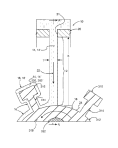
[00061] In one embodiment, the slurry curtain 12 has a length (I) and a
thickness (t) as
shown in FIG. I and FIG. lA with the length substantially greater than the
thickness. The slurry
curtain 12 is configured to shape the slurry flow so that it is configured to
cover all or a portion
of the overall axial length or height of the pattern assembly, generally
approximately the length
or height of the sprue pattern. The investment mold slurry curtain apparatus
10 also includes an
outlet 20. The outlet 20 is configured to dispense the slurry fluid 14 and the
slurry flow 22 and
form the
CA 2992604 2019-07-31
CA 02992604 2018-01-15
WO 2017/066374
PCT/US2016/056728
slurry curtain 12, including foritingthe slurry-curtain into a predetermined
shape.
The outlet 20 may have any suitable shape or configuration suitable to direct
the
slurry flow 22 of the slurry fluid 1.-4 into the shape of a curtain. In one
embodiment,
the outlet 20 may comprise an enclosed orifice 21 (FIGS. 1 and 1A) or
plurality of
enclosed orifices in a manifold, conduit, tank: or similar device for
receiving,
accumulating or directing the slurry flow 22 of the slurry fluid 14 that has
an orifice
shape suitable to direct the Slurry flow of the slurry fluid into the shape
aslurry
curtain 12 as described herein. In another embodiment, the outlet 20 may
include an
edge 23 (FIG. 2), or a plurality of edges, of a manifold, conduit, tank or
similar device
for receiving, accumulating or directing a flow-of theslurry fluid that has an
edge
shape suitable to direct the slurry flow 22 of the slurry fluid 14 over the
edge into a
slurry curtain 12 as described herein.
[00621 In one embodiment, the. outlet 20 has an outlet shape 20', and the
outlet shape is adjustable or changeable so that the shape of the slurry
curtain 12
produced by the natiet 20' is adjustable or changeable, such as, for example,
by the
use of moveable plates 25 or shutters (FIG. 3) that can be loosed/fixed using
threaded
fasteners 27. In one aspect, the outlet shape 20' may be adjustable while the
slurry
curtain 12 is being dispensed. For example, the outlet 20 may be adjustable to
provide
a range of slurry curtain thicknesses alone the length, or the length may be
adjustable
over a range of lengths, or the outlet 20 may be adjustable so that both the
thickness
and length of the slurry curtain 12 may be adjustable. In one embodiment, the
shape
of the-Oudot 20 may be adjusted manually, such as part of the set-up of the
shape of
the outlet 20, or alternately, while the shiny fluid 14and slurry flow 22 is
flowing
through the outlet 20. In another embodiment, the outlet..20 maybe adjusted
automatically using an electronic controller and electromechanical actuators,
such as
part of the set-up of the shape of the outlet 20, or alternately while the
slurry fluid 14
is flowing through the outlet 20.
[00631 in one embodiment, the outlet 20 has an outlet shape that provides a
flow of the slurry fluid 14 such that the slurry curtain 12 comprises a flat
Plane (FIGS.
1, IA, and 2). In another einhodiment, the outlet 20 has an outlet shape that
provides
a flow of the slurry fluid 14 such that the slurry curtain 12 comprises a
curved plane.
The slurry curtains 12 may have a single shape, such as a flat plane or a
curved plane
(FIG. 4), or may combine a plurality of flat plane and curved plane portions
or
11
CA 02992604 2018-01-15
WO 2017/066374
PCT1US2016/056728
segments (FIG. 4) to accommodate the various shapes of the pattern assembly.
The
outlet 20 may comprise a plurality of outlets 20 that together may define one
slurry
curtain 12 or a plurality of slurry curtains 12 (FIG. 5).
[00641 The slurry curtain 12 has a length (I) and a thickness (0 as shown in
FIGS 1, IA with the length substantially greater than the thickness. in this
regard,
the Meaning of substantially-greater-than includes greater than, and in one
embodiment may be defined as being 5 times greater or more. In another
embodiment, the length of the slurry curtain 12 is about 5 to about 1000 times
the
thickness, and in another embodiment, the length of the Slurry curtain is
about 20 to.
about 500 times the thickness. The Slurry curtain 12 may have any suitable
thickness,
and in one embodiment is greater than about ONO inches, and in another
embodiment
may range from about 0.040 inch.es to about 0.50 inches, and more particularly
from
about 0.040 inchatortbout 0,10 indica. In one embodiment, the thickness of the
slurry curtain 12 iseonstant along the length of the curtain. In one
embodiment, the
thickness of the slurry curtain 12 varies along the length of the curtain
(FIG. 6). In
some aspect, the thickness of the slurry curtain 12- maybe -constant in the
plane and/or
curved plane portions along the length of the slurry curtain12. In another
aspect, the
thickness of the slurry curtain 12 may he variably adjusted in the plane
and/or curved.
plane portions along the length of the slurry -curtain 12 to accommodate the
various
shapes of the pattern assembly 18.
[00651 blow embodiment, the shirty curtain 12 comprises a single slurry
curtain 12.(FIGS. I, IA, and 2) that is configured to cover the entire length
of the
pattern assembly 18, or only a predetermined portion of the .patternassembly
18, as
the case may be. In another embodiment, the slurry curtain 12 comprises a
plurality
of discrete slurry curtains 12-(FIGS. 4, 5 and 6) that together are configured
to cover
the entire length of the pattern assembly 18, or only a predetermined portion
of the
pattern assembly 18, as the ease may be. Discrete slurry curtains 12 may be
configured in any predetermined pattern in order to provide the desired
coating
coverage of the pattern assembly 18, including the patterns shown in FIG. 6,
Investment Mold Slurry Coating Apparatus
100661 In another embodiment, an investment mold slurry coating apparatus
.100 includes a conduit 30 configured to receive the slurry flow 22 of the
slurry fluid
12
CA 02992604 2018-01-15
WO 2017/066374
PCT/US2016/056728
14 and an outlet 20 operatively coupled to the conduit 30 as illustrated in
rms. 7,-8,
and 813. In one aspect, the investment mold slurry curtain apparatus 10 may
include or
be operatively connected to the investment mold slurry coating apparatus 100L
In this
embodiment, the investment mold slurry coating apparatus 100 combines the
conduit
30 and outlet 20 and the outlet is configured to dispense the slurry flow 22
of the
slurry fluid 14 as slurry curtain 12, as described herein. In this embodiment,
a conduit
system 32, which is generally used to convey the Slurry fluid 14 from a tank,
vat,
mixer, or similar device 34 that may be used to prepare the slurry fluid from
its
constituents or store the slurry fluid 14 once it has been prepared, or a
combination
thereof, or any other suitable source 35 of slurry fluid 14, is used to convey
the slurry
flow 22 to the conduit 30 that includes the outlet 20 for dispensing the flow
of slurry
fluid 14 as slurry curtain 12. In one embodiment, the conduit :30
advantageously may
be used to directly dispense the slurry fluid 14 from the outlet 20 without
the need For
a device or devices to accumulate slurry fluid 14 adjacent to the outlet. In
addition,
the outlet 20 may be incorporated into any suitable portion of the conduit 30,
including at an end 36 as shown in FIG. 13A and FIG. 13C or along the length
38 Of
the conduit as shown in FIG, 14A.
100671 The conduit 30 may have a size or shape, including cross-sectional
shape. In one embodiment, the conduit 30 may comprise a length of a pipe or
tube
40. The pipe or tube 40 may have any suitable cross-sectional shape, including
various circular. rectangular, and rounded rectangular cross-sectional shapes,
including square and rounded square cross-sectional shapes. The conduit 30 may
be
curved or bent along the longitudinal axis. In one embodiment, the conduit 30
may
have a circular cross-section or square cross-section with a diameter or side
length in
a range of about 0.25 in. to about 12 in., and more particularly about 1 in.
to about 3
in. The conduit 30 may be formed from any suitable material, including various
plastics, metals, or composite materials, including fiber-reinforced composite
materials, such as various fiberglass or carbon composites. Suitable metal
conduits
include copper, aluminum, steel, stainless steel, and iron pipe or tubing.
Suitable
plastic conduits include those formed from any suitable engineering
thermoplastic or
thermoset resins, including acryloni trite butadiene styrene, polyvinyl
chloride,
chlorinated polyvinyl chloride, polyester, polyethylene, and cross-linked
polyethylene, polypropylene, polybutylene, polyamide, epoxy, and phenolic
resins,
13
CA 02992604 2018-01-15
WO 2017/066374
PCT/US2016/056728
which may be filled with any suitable tillers or strengthening fibers.
Composite
conduits include resins of the types described above that are reinforced by
glass,
metal, or carbon fibers in various forms, including various wound, wrapped,
and
woven forms. The conduit 30 may be rigid or flexible. The conduit 30 may also
be
lined on an inner surface 31 with a liner 42. The liner 42 and liner material
44 may be
selected to provide at least one of increased chemical resistance, increased
abrasion
resistance, or a reduced coefficient of friction with regard to the slurry
fluid 14 as
compared with the material of the conduit. Suitable liner materials may
include
various metals or metal carbides, oxides, and nitrides, or combinations
thereof, or
diamond like carbon (DLC) films or coatings having a hardness or abrasion
resistance
that is greater than the material of the conduit 30, including those materials
used as
hard-facing materials in the oil and gas services, such as hard particle-metal
matrix
composites. The liner material 44 may also include various polymer materials
to
reduce the coefficient of friction with regard to the slurry fluid 14,
including various
fluoropolymers such as polytetrafluoroethylene (PTFE). The liner material 44
may be
applied in any suitable manner, including by heat treatment or as a coating or
film
deposited on the inner surface 31 of the conduit $0.
[00681 The conduit 30 may he attached to the conduit system 32 with any
suitable connection or coupling, including flexible or movable or adjustable
couplings, such as by various conduits that allow movement of the conduit 30
relative
to the conduit system 32. Flexible couplings 33 may, for example, include all-
manner
of flexible hoses suitable to transport slurry fluid .14 and movable or
adjustable
fixtures, including movable or adjustable 3-axis fixtures or tables. The
couplings 33
may also be movable or adjustable to enable translation or movement of conduit
30
along three mutually orthogonal directions or axes (eat. x-y-z), or radial or
pivoting
movement about one end of the conduit 30, or a combination thereof These
couplings 33 enable adjustment of the conduit 30, outlet 20, and the slurry
curtain 12
in any desired direction or angular orientation, particularly in a direction
along the
length or a longitudinal central axis of the curtain, relative to the fugitive
pattern
assembly 18 to be coated, and particularly relative to the longitudinal or
sprue axis 26
of the fugitive pattern assembly. In one embodiment, the conduit 30, outlet
20, and
the slurry curtain 12 may be positioned so that a longitudinal conduit axis 28
is
substantially parallel, including parallel, to or co-planar with the sprite
axis 26. In this:
14
CA 02992604 2018-01-15
WO 2017/066374
PCT/US2016/056728
embodiment, the conduit 30, outlet 20 and slurry curtain 12 are moveable about
at
least. one axis of three mutually orthogonal axes by translation along the at
least one
axis. In this way, the conduit 30, outlet 20 and slurry curtain 12 can be
flexibly
positioned relative to the part to be coated. This includes movement to
control the
fore/aft position of the slurry curtain 12 relative to the fugitive pattern
assembly 18 as
it impacts the assembly; the side to side movement and positioning of the
conduit 30,
outlet 20 and slurry curtain 12 relative to the opposing ends of the fugitive
pattern
assembly 18, particularly the sprue portion of the pattern assembly, to allow
centering
or other adjustment of the SitirtY Curtain 12-Over the fugitive pattern
assembly 18; as
well movement to control the distance between the outlet 20 and the surface of
the
fugitive pattern assembly 18 and the height of the slimy curtain 12. in
another
embodiment, the conduit 30, outlet 20, and the slurry curtain 12 may be
pivoted and
positioned so that a longitudinal conduit tuck 28 is not substantially
parallel, including
not parallel, to the sprue axis 26, such that the conduit 30, outlet 20, and
slurry curtain
12 are disposed at an angle (a) relative to the sprue axis 26. The angle may
be any
suitable angle, including an angle of about 0 to about 90 degrees in either
direction,
and more particularly about 1 to about 90 degrees in either direction, and
even more
particularly about 10 to about 80 degrees in either direction (e.g
upward/downward).
Angular pivoting movement may be combined with movement along orthogonal axes
to provide great flexibility in how the slurry curtain 12 is positioned
relative to the
fugitive pattern assembly 18. This may be described in an embodiment as the
outlet
20 and slurry curtain 12 being moveable about at least one axis of three
mutually
orthogonal axes by translation along the at least one axis, rotation about the
at least
one axis, or a combination thereof The flexible coupling 33 may also enable
rotation
of the conduit 30 and outlet 20 about the conduit axis 28 to affect the radial
location
or position at which the slurry curtain exits the outlet 20. The angle q.÷ may
be any
suitable angle, including an angle of about 0 to about 180 degrees, and more
particularly about 1.0 to about 170 degrees, and even more particularly about
45 to
about 135 degrees. This enables the conduit 30, conduit axis 28, and slurry
curtain 12
to be angled horizontally fore or forward or aft or rearward, or to be
directed at any
acute angle fore or aft, with reference to the sprite axis 26 or a direction
of motion 29
of the assembly 30.2 in cases where the assembly is moved through the slurry
station
that includes conduit 30 (or any of apparatuses 10,. 100, 200). The couplings
33,
including flexible or movable or adjustable couplings, may be manually
adjustable by
CA 02992604 2018-01-15
WO 2017/066374
PCT1US2016/056728
a human operator, or may be automatically -adjustable by employing various
electromechanical linear actuators 70 or rotary actuators 72, or a combination
(hereof,
that are operatively coupled to an electronic controller 74, such as a.
programmable
microcontroller or computer. The programmable mierocontroller or computer may
include one or more computing systems that include any appropriate type of
general
purpose microprocessor,. digital signal processor, microcontroIler, dedicated
hardware, transceiver (Communicating over a communication channel as defined
herein), or the like. The computing systems- may further include or be
connected to
the madam. access Memory (RAM), the read-only tnetnory (ROM), a storage
device,
the network interface and the like. Thecomputing systems may execute sequences
of
computer program instructions to perform various processes. The computer
program
instructions may be loaded into the RAM for execution by the processor from
the
ROM, from a communication channel.(wired or wireless), from the storage device
and/or the like. The storage device may include any appropriate type of
storage
provided to store any type of information that the control device may need to
perform
the processing. In the case of automated control of the adjustment or movement
of the
conduit 30, outlet 20 and slurry curtain 12, the adjustment or movement may be
used
as partof an initialsettipprior to applying the wet coating layer and fixed
during
application of the layer. Alternately, the automated -control of the
adjustment or
movement of the conduit 30, outlet.20 and Slum curtain 12 may also be employed
to
Move the slurry curtain 12 while applying the wet coating layer. In one
embodiment,
the outlet 20 may comprise a single circular outlet that produces a
substantially
circular, including circular stream, of the slurry fluid 14 as slurry flow 22.
and the
conduit 30 and outlet 20 may be-rapidly translated or shuttled back and forth
along the
conduit axis 28 such that the movement of the circular stream provides a
partial or
quasi slurry curtain 12 having a length that is substantially greater than the
diameter
of the stream (FIGS 9-10). In this embodiment, the outlet 20 has an outlet
opening
48, the conduit 30 is movable, and slurry flow 22 of the slurry fluid 14
through the
outlet opening 48 and movement of the conduit 30 provides the slurry curtain
12. In
addition to the movement: or adjustment of the conduit 30, outlet 20 and
slurry curtain
12 as described above, the fugitive pattern assembly 18 may also be movably
positioned relative to the conduit 30, outlet 20 and slurry curtain 12 as
described
herein, including rotation, translation and angulation under the slurry
curtain 12. In
one embodiment, the conduit 30, outlet 20, and slurry curtain 12 are
operatively
16
CA 02992604 2018-01-15
WO 2017/066374
PCT/US2016/056728
coupled to an investment mold assembly conveyor 80. In an embodiment, the
investment mold assembly conveyor 80 is configured to tam* convey a refractory
shell mold assembly and/or investment mold assembly 600 including the
ittgitive
pattern assembly 18 under the slurry curtain 1.2 in a predetermined direction
82 (FIG...
30). In an embodiment, the predetermined direction 82 is substantially
orthogonal to
a plane defined by the. slurry curtain 1.2. In another aspect, the
predetermined
direction 82 may have an angle equal to or less than 90 degrees or may be
slanted to
the plane defined by the Slurry curtain 12. in one embodiment, the refractory
shell
mold assembly and/or the investment mold assembly 600 is rotatably disposed
along a
Mold axis, such as sprue axis 26, and the mold axis is disposed substantially
horizontally, including horizontally. As used herein, horizontally mean
parallel to the
surface of the earth, including the horizon, at that location.
(0069.1 Thecondint 30 may be positioned as described herein
circumferentially with reference to and relative to the fugitive pattern
assembly 18
and sprue axis 26 at any predetermined circumferential location (e.g. from 0
to 360
degrees about the assembly) and predetermined radial spacing or distance (e.g.
d and
d2, Where d2>dt) from the assembly (FIG. 12). For example, theconduit 30 may
be
positioned vertically above the fugitive pattern assembly 1.8 at a
predetermined radial
spacing or distance such that the slurry curtain 12 is directed downwardly at
the
fugitive pattern assembly 18 (e.g. at 0 degrees). Alternately, the conduit 30
may be
positioned vertically below the 'fugitive pattern assembly 18 at a.
predetermined radial
spacing or distance Such that -the slurry curtain 12 is directed upwardly at
the fugitive
pattern assembly 18 (e.g.. at I 80.degrees using the same circumferential
point of
reference as the previous example). In other embodiments, the conduit 30 may
be
positioned at any other predetermined circumferential. position.
poxj The conduit 30 includes an outlet 20 that may be incorporated into any
suitable portion of the conduit 30, including at an end 36 or along the length
38 of the
conduit. In one embodiment, the outlet 20 comprise a nozzle 46 disposed at an
end of
the conduit wherein the nozzle 46 defines an outlet opening 48 that is
configured to
produce the slurry curtain 12 (FIGS. 13A-13C). Thenozzle 46 may be formed from
or have an interior surface that is lined With a material 50 selected to
provide at least
one of increased chemical resistance, increased abrasion resistance, or a
reduced
coefficient of friction, which may be the same materials as described above
for liner
17
CA 02992604 2018-01-15
WO 2017/066374
PCT1US2016/056728
material 44. The outlet opening 48 may include a plurality of openings 48. The
opening 48 or openings 48 may have any suitable opening configuration that is
configured to produce shiny curtain. 12 as the slurry flow 22 exits the
opening 48. In
one embodiment, the outlet opening 48 of the nozzle 46 may be configured by
being
shaped to provide the slutry curtain 12, including as a. slot 52 or a
plurality of adjacent
slots 52, which have a length that is substantially greater than a width. The
slot or
slots 52 may include any suitable configuration, including various rectangular
and
curved planar slot configurations, ora combination thereof. hi one embodiment,
the
outlet opening 48 of the nozzle 46 may be configured by being shaped to
Provide the
shiny curtain 12, including as a plurality of adjacent holes 54, which define
a hole
pattern 56 that has a length that is substantially greater than the width
(FIGS 14A-
.148). The holes 54 may include any suitable pattern configuration, including
various
rectangular and carved planar pattern configurations, or a combination thereof
In one
embodiment, the holes 54 may be arranged in a hole pattern 56 comprising a
plurality
of rows 58 and columns 60. In another embodiment, the hole pattern 56 may
include
a plurality of rows 58 and columns 60, wherein the holes of adjacent rows 58
and/or
columns 60 are ofTset with respect to one another by a predetermined offset
distance
d1 and di, where d.) and d, may be the same or different,
(00711 In another embodiment, the nozzle 46 may include a transition section
62 that extends between the conduit 30 and the outlet 20 (FIG. 13C). The
transition
section 62-may include ntransition chamber 64 that is configured to shape the
slurry
flow 2.2 prior to reaching the outlet 20 to enhance the slurry flow 22 within
the slurry
curtain 12. The transition chamber 64 may, for example, promote uniformity of
the
slurry flow 22-at the outlet 20 and withinglutry curtain.12, which may in turn
promote uniformity of the thickness(t) of the Wet Coating layer 16 as it is
being
applied to the mold pattern assembly 18. The transition section 62 and
transition
chamber 64 may have arty suitable shape and size. Uniformity of the thickness
of the
wet coating layer 16 is very advantageous as it. relates directly to the
thickness of the
plurality of the dried coating layers that ultimately constitute the mold wall
of the
refractory molds described herein, Uniformity of the mold wall thickness is
advantageous as it directly or indirectly affects the heating and cooling of
the mold
wall in preparation for and during casting of articles within the refractory
molds, and
the resultant microstructure and properties of the cast articles.
18
CA 02992604 2018-01-15
WO 2017/066374
PCTIUS2016/056728
100721 In certain embodiments (e.g. FIG. 11), .the outlet 20 comprises an
integral portion of the conduit 30 and is disposed along the length 38 of the
conduit
30. The outlet 20 includes an outlet opening .48 that is configured to produce
the
slurry curtain 12. The outlet 20 may simply include an opening or a plurality
of
openings 48 in a wall-66 of the. conduit 30. Alternately, the opening 48 may
be
defined by an insert 68. disposed in the wall 66 of the conduit 30 (F1(1. 15),
The insert
68 is disposed in an insert opening 69 that is configured to receive the
insert. In one
embodiment, the insert 68 may be permanently affixed or attached to the
conduit 30.
Alternately, the insert (i8 may be configured such that it is selectively
insertable into
and removable from the insert opening 69. The insert 68 may be fort:tied from
the
same material as conduit 30. Alternately, the insert 68 may be formed from or
have
an interior surface that is lined with a material 50 selected to provide at
least one of
increased chemical resistance, increased abrasion resistance, or a reduced
coefficient
of friction, which may be the same materials as described above for liner
material 44.
In one aspect, the insert material has greater abrasion resistance to the
slurry than the
manifold material. The outlet opening 48 may include a plurality of openings
48. The
opening or orifice 48 or openings or orifices 48 may have any suitable opening
configuration that is configured to produce slurry curtain 12 as the slurry
flow ;1.2 exits
the opening. In one embodiment, the outlet opening 48 of the insert 68 may be
configured by being shaped to provide the slurry curtain 12, including as a
slot 52 or a
plurality of adjacent Slots 52 (FIG. 13B), which have a length that is
substantially
greater than a width. In one embodiment, a slot 52 may include a plurality of
spaced
strengthening or reinforcing ribs 53 extendingacross and bridging the slot 52
and
thereby defining a plurality of adjacent slots 52. The ribs 53 may be
utilized, for
example, to maintain the width of the slot along its length and prevent
distortion of
the slot width by the fluid pressure of slurry flow 22, and thereby maintain
the shape
and consistency of the width of the slurry curtain 22 along its length. The
slot or slots
52ntay include any suitable configuration, including various rectangular and
curved
planar slot configurations, or a combination thereof. In one embodiment, the
outlet
.opening 48 of the nozzle 46 may be configured by being shaped to provide the
slurry
curtain 12, including as a plurality of adjacent holes 54, which define a hole
pattern
56 that has a length that is substantially greater than the width. The holes
54 may
include any suitable pattern configuration, including various rectangular and
curved
planar pattern configurations, or a combination thereof. In one embodiment,
the boles
19
CA 02992604 2018-01-15
WO 2017/066374
PCTIUS2016/056728
54 may be arranged in a hole pattern 56 including a plurality of rows 58 and
columns
60. in another embodiment, the hole pattern 56 may include a plurality of rows
58
and columns 60, wherein the holes of adjacent rows 58 and/or columns 60 are
offset
with respect to one another by a predetermined offset distance d) and 42,
where d E and
d2 may be the same or different. The size and shape of the outlet opening 48
whether
integral with the conduit or defined by the insert 68 may be fixed, or may be
adjustable. In the case of fixed openings 48 in the conduit 30 or an insert 68
that
defines opening 48, the size and shape may be adjusted by incorporation of a
separate
adjustment mechanism 76, such as a Movable shutter 78 (FIG. 16), including a
shutter
that is movably disposed on the conduit 30 to contrathe length or the width of
the
opening, or a combination thereof In the case of an insert 68, a portion of
the insert
68 may be adjustable to define the size and shape of the opening 48, including
the
length or the width, or a combination thereof In one embodiment, the
adjustment
mechanism 76 may also be configured. to selectively open or close the outlet
20,
Alternately, a valve mechanism 79 (FIG. 16) may be disposed in or on conduit -
30
proximate outlet 20 to selectively open or close the outlet 20.
10031 The conduit 30 may include a conduit. chamber 69 in the portion of the
conduit adjacent to the outlet 20 and/or insert 68 that is configured to Shape
the slurry
flow 22 prior to reaching the outlet 20 to enhance the slurry flow 22 within
the slurry
curtain 12. The conduit chamber 69 may, for example, be shaped (e.g. narrowed
or
restricted, or in some embodiments broadened) to promote uniformity or enhance
the
flow rate of the slurry flow 22 at the outlet 20 and within slurry curtain
12,.which may
in turn promote uniformity of the thickness (t) of the wet coating layer 16 as
it is
being applied to the mold pattern assembly 18. The conduit chamber 69 may have
any suitable shape and size. Uniformity of the thickness of the wet coating
layer 16 is
very advantageous as explained herein.
[0074] In one embodiment, the conduit system 32 and conduit 30 may be
configured to deliver the slurry flow 22 of slurry fluid 14 to the outlet 20
such that it
is configured to dispense the slurry curtain 1.2 as a gravity slurry curtain.
In other
words, the stuffy flow 22 may be provided through the conduit system 32. and
conduit
30 where it exits the outlet 20 as a slurry curtain by the force of gravity.
The conduit
system 32 and conduit 30, as well as outlet 20, including outlet opening-48 or
openings 48 may be selected to deliver slurry fluid 14 by gravity ata
predetermined
CA 02992604 2018-01-15
WO 2017/066374
PCTIUS2016/056728
flow rate. The predetermined flow rate may be any suitable-predetermined flow
rate
to achieve the desired slurry curtain 12 characteristics, or to provide the
desired
amount of material at the surface 24 of the fugitive pattern assembly lg, or
in the case
of second or subsequent wet coating layers 16, a previously de-posited coating
layer
that has been deposited on the fugitive pattern assembly 18. The predetermined
flow
rate may also be a function of the size of the fugitive pattern assembly 18,
including
the surface area thereof. In one embodiment, the predetermined flow rate may
be at
least about 0.5 gallons/minute, including a range of about 0.5 to about 20
gallons/minute,- and more particularly about 1 to about 5 gallons/minute. In
one
embodiment thepredetermined flow rate may be selected to achieve a
predetermined
coating layer thickness of the wet coating layer 16 being deposited or
disposed on the
fugitive pattern assembly 18. The predetermined flow rate should be high
enough to
provide sufficient Slurry fluid 14 at the surface to achieve the predetermined
coating
layer thickness but not so high as to prevent the establishment of the wet
coating layer
16 or disrupt or erode previously deposited portions of the wet coating layer
16, such
as, for example, as the fugitive mold pattern assembly 18 is rowed under the
slurry
curtain 12 and previously deposited portions of the wet coating layer 16 are
rotated
under the slurry certain 1.2..
(007$) In another embodiment, the conduit system 32 and conduit 30 may be
configured to deliver the slurry flow 22 as a pressurized flow of slurry fluid
14 to the
outlet 20 such that it is configured -to dispense the shirty curtain .12 as a
pressurized
slurry curtain 12. In other words, the shirty flow 22 may be provided through
the
conduit system 32 and conduit 30 where it exits the outlet 20 as a slurry
curtain 12
under pressure. The pressurized flow ofslwryfluid 14 may be produced by using
a
Suitable slurry pump 37 to pump the slurry fluid 14 through the conduit system
32 and
conduit 30 (e.g. FIG. 11). When the slurry flow 22 comprises a pressurized
slurry
flow, any suitable fluid pressure may be utilized to achieve a predetermined
flow rate
of the slurry flow 22 from the outlet 20. In one embodiment, the fluid
pressure may
be in a range of 0.5 to 50 psis, and more particularly Ito 25 psig.
(0076) In one embodiment, the conduit 30 comprises a plurality of conduits 30
that arc operatively connected to the conduit system 32 for fluid
communication of
the slurry flow 22 and. slurry fluid 14, and the outlet 20 includes a
plurality of outlets
20 corresponding to the conduits 30 that are configured to receive a
corresponding
21
CA 02992604 2018-01-15
WO 2017/066374
PCT1US2016/056728
plurality of slurry flows 22 Of the slurry fluid 1410 dispense the flows-of
the slurry as
corresponding slurry curtains 12 (FIG. II): The plurality of conduits 30 may
all be
coupled with couplings 33 as described herein such that they may be fixed or
movable
relative to one another either during setup prior to depositing the respective
wet
coating layers 16 or during the deposition of the respective wet coating
layers 16. The
conduits 30 may be configured and used to incorporate a plurality of slurry
curtains
12 within a sink slurry coating station as described herein. Alternately, the
conduits
30 may be used to incorporate a plurality of slurry curtains 12 into a
plurality of slurry
coating stations, including providing one Or a plurality of slurry curtains
1.2 into
plurality of shiny coating stations. Coating with the investment mold shirty
eoating.
apparatus 100 may be carried out in air, vacuum and/or controlled environment.
Investment Mold Slurry Coatina Manifold Apparatus
[00771 In another embodiment of a slurry coating apparatus, an investment.
mold slurry coating manifold apparatus 200 includes a slurry manifold 210
having a
slurry chamber 212 configured to receive the slurry flow 22 of the slurry
fluid 14 as
shown in 'FIGS. 17A-17C. In one aspect, the investment mold slurry coating
manifold
apparatus 200 includes or is operatively connected to an investment mold
slurry
curtain apparatus 10 and/or an investment mold slurry coating apparatus WO.
The
apparatus 200 also includes an inlet conduit 220 disposed on the slurry
manifold 210,
which has an inlet opening 223 into the slurry chamber 212. The inlet conduit
220 is
configured to provide the slurry flow 22 into the slurry chamber 212. The
apparatus
200 also includes an outlet 20 that is configured to dispense a slurry curtain
12, as
described herein.
[00781 In one embodiment, the investment mold slurry coating manifold
apparatus 200 may be similar to investment mold slurry coating apparatus 100,
such
as where the slurry manifold 2.10 includes a condnit-30 with a single
inletconduit.220
to provide the slurry fluid 14 (FIGS. 17A-17C). In other embodiments, the
investment mold slurry coating manifold apparatus 200 includes a plurality of
inlet
conduits 220 to supply a plurality of shwry fluids 14 or other fluids or a
plurality of
outletconduits 210, or both (FIGS. 18A, 1.8B). In addition, the slurry
manifold 210
may be configured (e.g. by adjusting the flow rate) other than as a conduit 30
that
generally dispenses the slurry flow 22 received such that it may accumulate a
portion
22
CA 02992604 2018-01-15
WO 2017/066374
PCTIUS2016/056728
of slurry fluid 14 and maintain slurty flow 22 through the outlet 20 even
lithe supply
or flow of slurry fluid 14 through the inlet conduit 220 to the manifold is
interrupted
momentarily or for a short period of time.
[00791 In one embodiment, an investment mold slurry coating manifold
apparatus 200 includes a slurry manifold 210 configured to receive the slurry
flow 22
oftheShuty fluid .14 and an oudet20 operatively coupled to the manifold 210 as
illustrated in FIGS, 1.7A-17C. In this embodiment, the investment mold slurry
coating manifold apparatus 200 combines the slurry manifold 210, inlet conduit
220,
and.outlet20 and the outlet 20 is configured to dispense the slurry flow 22 of
the
slurry fluid 14 as shury curtain 12, as described herein. In this embodiment,
a conduit
system 32, which is generally used to convey the slurry fluid 14 from a tank,
vat,
mixer, or similar device that may be used to prepare the slurry fluid from its
constituents or-stem the slurry fluid 14 once it has been prepared, or a
combination
thereof, or any other suitable source 35 of slurry fluid 14, is used to-eonvey
the slurry
flow 22 to the inlet conduit 220 into the slurry manifold 210 that includes
the outlet
20 for dispensing the flow of slurry fluid 14 as slurry curtain 12. In one
embodiment,
the slurry manifold 210 advantageously may be used to accumulate slurry fluid
14 so
that it can be dispensed from the outlet 20. The outlet 20 may be incorporated
into
any suitable portion of the slurry manifold 210. In one embodiment, the outlet
20
may be disposed on the bottom 214 of the slurry manifold 210 and include an
outlet
opening 248 that has an opening shape 218 configured to provide the shapes of
the
slurry curtain 12 described herein. In the ease of outlet 20 disposed in the
bottom
214, the bottom may be a flat bottom. The bottom 214 may also be tapered
downwardly -to promote the slurry flow 22 through the outlet 20 and prevent
the
possibility of accumulation of non-flowing, Still or stagnant slurry fluid 14
adjacent to
the-outlet 20.as shown in FIGS. 17A-17C. In-other embodiments, the outlet 20
may
be diSposed along a side opening 222 or a top edge 224 of the slurry manifold
210
where it has an. outlet lip or edge 226 configured to provide the shapes of
the slurry
curtain 12 described herein. The outlet edge 226 may protrude outwardly away
from
the side opening 222 or top edge 224.a predetermined distance sufficient to
allow the
sluny flow 22 to cascade freely as slurry curtain 12 and prevent the slurry
curtain 12
from funning down the side 222 of the Murry manifold 210.
23
CA 02992604 2018-01-15
WO 2017/066374
PCT1US2016/056728
[00801 The slurry manifold 210 may have size or shape, including cross-
sectional shape. in one embodiment, the slurry manifold-210 May comprise an.
elongated enclosure 228 (e.g. FIG. 18A), including an elongated box, tube or
trough
having a width and a length that is substantially greater than the width. The
length
may be any suitable length, including a length sufficient to include the
desired outlet
20. The elongated enclosure 228 may have any suitable cross-sectional shape,
including various semi-circular, rectangular, and rounded rectangular cross-
sectional
shapes, including square and rounded square cross-sectional shapes. In one
eMbodiment, the elongated enclosure 228 may have a top side 232 that is open
like a
trongh(FIG. 17A). In other embodiments the top side 232 may be closed, or
partially
closed (FIG. 18B). Closed or partially close top sides 232 are advantageous in
that
they reduce the possibility of extraneous or contaminant materials from. being
introduced into the Slurry chamber 212 and slimy -fluid 14, -The-shory
manifold 210
haven circular cross-section or square cross-section with any suitable
diameter,
including a width of about 0.25 in. to about 12 in., and more particularly
about 1 in. to
about 3 in. The slurry manifold 210 may be formed from any suitable material,
including the Materials described herein for use with conduit 30. The slurry
manifold
210 may be rigid or flexible. The slurry manifold 210 may also be lined on an
inner
surface 234 with a liner 42 as described herein as shown in FIG. 19.
(00811 The slurry manifold 210 and inlet conduit 220 may be attached to the
conduit system 32 withany suitable connection or coupling, including flexible
or
movable or adjustable couplings, such as by various conduits that allow
movement of
the conduit 3G relative to the conduit system. The inlet conduit 220 may
comprise
this coupling. Flexible couplings may, for example, include an -manner of
flexible
hoses suitable to transport slurry fluid 14 and movable or adjustable
fixtures,
including movable or adjustable 3-axis fixtures or tables. The couplings may
also be
movable or adjustable to enable translation or movement along three mutually
orthogonal directions or axes (e.g. x,y-z), or radial or pivoting movement
about one
end of the conduit 30, or a combination thereof. These couplings enable
adjustment
of .the slurry manifold 210, outlet .20, and the slurry curtain 12. in any
desired direction
or angular orientation, particularly in a direction along the length or a
longitudinal
central conduit axis 28 of the manifold, relative to the fugitive pattern
assembly 18 to
be coated, and particularly relative to the longitudinal orsprne axis 26 of
the fugitive
24
CA 02992604 2018-01-15
WO 2017/066374
PCT1US2016/056728
pattern assembly. The slurry manifold 210, outlet 20, and the slurry curtain
12 may
be positioned, moved, pivoted, rotated and otherwise adjusted in the same
manner
described above with regard to the conduit 30, including incorporation of
automated
control. In one embodiment, the outlet 20 may comprise a single circular
outlet that
produces a substantially circular, including circular stream, of the slurry
fluid 14 as
slurry flow 22 and the slurry manifold 210 and outlet 20 may be rapidly
translated or
shuttled back and forth along the conduit axis -28 such that the movement of
the
circular stream provides a partial or quasi slurry curtain 12 as described
above for
conduit 30. In addition to the movement or adjustment of the slurry mandbld
210,
outlet 20 and slurry curtain 12 as described above, the fugitive pattern
assembly
may also be movably positioned relative to the slurry -manifold 210, outlet 20
and
slurry curtain 12 as described herein, including rotation, translation and.
angulation
under the slurry curtain 12. In one embodiment, the slurry manifold:210,
outlet 20,
and slurry curtain 12 are operatively coupled to an investment mold assembly
conveyor 80. In an embodiment, the investment mold assembly conveyor 80 is
configured to rotatably convey a refractory shell mold assembly and/or an
investment
mold assembly 600 including the fugitive pattern assembly 18 under the slurry
curtain
in a predetermined direction 82. In an embodiment, the predetermined direction
82 is substantially orthogonal to a plane defined by the slurry curtain 12. In
one
embodiment, the refractoty shell mold assembly and/or the. investment mold
assembly
600 is rotatably disposed along a mold axis, Such as sprue axis 26, and the
mold axis
is disposed substantially horizontally,including horizontally. As used herein,
horizontally mean parallel to the surface of the earth, including the horizon,
at that
location.
[00821 The slurry manifold 210 may also be positioned as described herein
circumferentially with reference to and relative to the fugitive pattern
assembly 18
and spree axis 26 at any predetermined circumferential location (e.g. from 0
to 360
degrees about the assembly) and predetermined radial spacing or distance from
the
assembly, as shown in FIG. 12. For example, the slurry manifold 210 may be
positioned vertically above the fugitive pattern assembly 18 at a
predetermined radial
spacing Or distance such that the slurry curtain 12 is directed downwardly at
the
fugitive pattern assembly 18 (e.g. at 0 degrees). Alternately, the slurry
manifold 210
May be positioned vertically below the fugitive pattern assent* 18 at a
CA 02992604 2018-01-15
WO 2017/066374
PCT1US2016/056728
predetermined radial spacing or -distance such that the slurry curtain .12 is
directed
upwardly at the fugitive pattern assembly (ex. at 180 degrees using the same
circumferential point Of reference as the previous example). In other
embodiments,
the slurry manifold 210 may be positioned at any other predetermined
circumferential
position.
100831 In certain embodiments, theoutlet 20 and an outlet opening 248 may
be incorporated directly into the slurry manifold 210 as described above on
the
bottom 214, as a side opening 222, or a top edge 2.24. In an embodiment where
the
slurry manifold 210 and slurry flow 22 arc pressurized, the outlet opening 248
may
alternately also be incorporated in the top 236 of shirty manifald 210,
such that
the slurry curtain 12 is projected upwardly toward the fugitive pattern
assembly 18
(FIG. 20). In these embodiments, the outlet 20 comprises an. integral portion
of the
'slurry Manifold 210 and is disposed along the length-238 of the slurry
manifold 210.
The outlet 20 includes an outlet opening 248 that is configured to produce the
Starry
curtain 12. The outlet 20 may simply include an opening 216 .or a plurality of
openings 216 in the respective wall 266 of the slurry manifold 210.
Alternately, the
opening 216 may be defined by an insert 268 disposed in the wall 266 of the
slurry
manifold 21Ø Theinsert 268 is disposed in an insert opening 20 that is
configured
to receive the insert. lit one embodiment, the insert 268 may be permanently
affixed
or attached to the slurry manifold 210. Alternately, the insert 268 may be
configured
such that it it selectively :insertable into and removable from the insert
opening .269.
The insert 268 may be formed from the same material as slurry manifold 210.
Alternately, the insert 268 may be fomied from or have an interior surface
that is lined
with a material 50 selected to provide at least one of increased chemical
resistance,
increased abrasion resistance, or a reduced coefficient of friction, Which may
be the
same materials as described above for liner material 44. The outlet opening
248 may
include a plurality of openings 248. The opening or orifice 248 or openings or
orifices 248 may have any suitable opening configuration that is configured to
produce slurry curtain 12 as the slurry flow 22 exits the opening. In one
embodiment,
the outlet opening:248, whether in the wall 266 or the insert 268 may be
configured
by being shaped to provide the slurry curtain 12 in the same way as described
above
regarding opening 48 in wall 66 or insert 68, including as a slot 52 or a
plurality of
adjacent slots 52, which have a length that is substantially greater than a
width. The
26
CA 02992604 2018-01-15
WO 2017/066374
PCT/US2016/056728
slot or slots 52 may include any Suitable configuration, including various
rectangular,
arcuate, and curved planar slot configurations, or a-combination thereof In
one
embodiment, the outlet opening 248 may be Configured by being shaped to
provide
the slun-y curtain 12, including as a plurality of adjacent holes 54, which
define a hole
pattern 56 that has a length that is substantially greater than the width. The
holes 54
may include any suitable pattern configuration, including various rectangular
and
curved planar pattern configurations, or a combination thereof in one
embodiment,
the holes 54 may be arranged in a hole pattern 56 comprising a plurality of
rows 58
and columns 60. In another embodiment, the hole pattern 56 may include a
plurality
of rows 58 and columns 60, wherein the boles of adjacent rows 58 and/or
columns 60
are offset with respect to one another by a predetermined offset distance di
and d2,
where di and d2 may be the same or different. The size and shape of the outlet
Owing 248 whether integral with the starry manifold -210 or defined by the
insert
268 May be fixed, or may be adjustable, in the case of fixed openings 248 in
the
slurry manifold 210 or an insert 268 that defines opening 248, the size and
shape may
be adjusted by incorporation of a separate adjustment mechanism 276, such as a
movable shutter 278, including a shutter that is movably disposed on the
slurry
manifold 210 to control the length or the width of the opening, or a
combination
thereof. In the case of an insert 268, a portion aft, insert may be adjustable
to
define the size and shape of the opening 248, including the length or the
width, or a
combination thereof In one embodiMent, the adjustment mechanism 276 may also
be
configured to selectively open or close the outlet 20. Alternately, a valve
Mechanism
279 may be disposed in slurry manifold 210 proximate outlet 20 to selectively
open or
close the outlet 20 (FIG. I 8B).
[00841 In certain other embodiments, the outlet 20 of slurry manifold .210 may
be incorporated into or disposed on one or more outlet conduits 230 that are
operably
attached to the wall 266 on one or more of the bottom 214, side 215, or an
enclosed
top side 232, or a. combination thereof in flow communication so as to receive
slurry.
flow 22. The outlet conduits 230 may incorporate outlet 20 in the same manner
as
described above with regard to conduit 30 including incorporation into any
suitable
portion of the conduit 30, Including at an end 36 or along the length 38 of
the conduit.
The outlet conduits 230 may 'be configured and used to incorporate a plurality
of
slurry curtains .12 within a -single slurry coating station as described
herein.
27
CA 02992604 2018-01-15
WO 2017/066374
PCT1US2016/056728
Alternately, the outlet conduits 230 may be used to incorporate a plurality of
sluny
curtains 12 into a plurality of slurry coating stations, including providing
one or a
plurality of slurry Curtains 12 into a plurality of slurry coating stations.
In the case of
the plurality of outlet conduits 230 and conduits 30, the outlet conduits
andior
conduits may be fixed or movable. Movable outlet conduits 230 and/or conduits
230
may be used to flexibly position the associated plurality of outlets 20 and
slurry
curtains .12 with regard to the mold pattern assembly 302.
[00851 In one embodiment, the conduit system 3.2 and slurry manifold 210,
including any outlet conduits 230, may be configured to deliver the slurry
flow 22 of
slurry fluid 14 to.the outlet 20 such that it is configured to dispense the
slurry curtain
12 as a gravity slurry curtain(FIGS. 17A-17C). In other words, the slurry flow
22
may he provided through the conduit system 12 and slurry manifold 210,
including
any outlet conduit 230, where it exita-the outlet 20 as a slurry curtain by
the force of
gravity. The conduit system 32 and slurry manifold 210, as well.as outlet 20,
including outlet opening 248 or openings 248. may be selected to deliver
slurry fluid
14 by gravity at. a predetermined flow rate. The predetermined flow rate may
be any
suitable predetermined flow rate to achieve the desired slurry curtain 12
characteristics, or to provide the desired amount of material at the surface
24 of the
fugitive pattern assembly 18, or in the case of second or subsequent wet
coating layers
16, a previously deposited coating layer that has been deposited on the
fugitive pattern
assembly 18. The predetermined flow rate may also be a function of the size of
the
fugitive pattern assembly 18, including the surface area thereof. In one
embodiment,
the predetermined flow rate may be at least about 0:5 gallons/minute,
including a
range of about. 0.5 to about 20 gallons/minute,. and more particularly about 1
to about
gallons/minute: Where a plurality :of outlet cow:huts-230-3re employed,- the
predetermined flow rate in each conduit may be controlled individually, such
as by
the use of a selectively openable and closable valves 240 operably disposed in
flow
communication in the respective outlet conduits, and the predetermined flow
rates
through the respective outlet conduits may be different. In one embodiment,
the
predetermined flow rate may be selected to achieve a predetermined coating
layer
thickness of the wet coating layer 16 being deposited or disposed on the
fugitive
pattern assembly 18. The predetermined flow rate should be high enough to
provide
stifficient slurry fluid 14 at the surface to achieve the predetermined
coating layer
28
CA 02992604 2018-01-15
WO 2017/066374
PCT1US2016/056728
thickness but not so high as to prevent the establishment of the wet Coating
layer 1-6 Or
disrupt or erode previously deposited portions of the wet coating layer 16,
suet' as, for
example, as the fugitive mold pattern assembly 18 is rotated wider the slurry
curtain
.12 and previously deposited portions of the wet coating layer 16 are rotated
under the
slurry curtain 12,
100861 In another embodiment, the conduit system 32 and slurry manifold.
210. including any outlet conduits 230, may be configured to deliver the slimy
flow
22 as a pressurized flow of slurry fluid 14 to the outlet 20 such that it is
configured to
dispense the slurry curtain 12 as a pressurized Slurry curtain (Fla 20). In
other
words, the shirty flow 22 may be provided through the conduit system 32-and
Slurry
manifold 210, including any outlet conduits 230, where it exits The outlet 20
as a
shirty curtain 12 under pressure. The-pressurized flow of slurry fluid 14 may
be
produced by using a suitable slurry pump to pump the slurry fluid through the
conduit
system 32 and slurry manifold 210. When the slurry flow 22 comprises a
pressurized
slurry flow, any suitable fluid pressure may be utilized to achieve a
predetermined
flow rate of the slurry flow 22 from the outlet 20. In one embodiment, the
fluid
pressure comprises 0.5 to 50 psi& and more particularly I to 25 psig. Where a
plurality of outlet conduits 230 are employedõ the predetermined flow rate and
fluid
pressure in each conduit may be controlled individually, such as by the use of
a
selectively ()portable and closable valves 240 operably disposed in .flow
communication in the respective outlet conduits, and the predetermined flow
rates and
fluid pressures through the respective outlet conduits may be different.
100871 in one embodiment, the slurry manifold 2.10 comprises a plurality of
slurry manifelds that are operatively connected to :Me conduit system 3.2 for
'fluid
communication of the-slurry flow 22 and slurry -fluid 14 and the outlet 20
comprises a
plurality of outlets 20 corresponding to the manifolds that arc configured to
receive a
corresponding plurality of slurry flows 22 of the slurry fluid 14 to dispense
the flows
of the slurry as corresponding slurry curtains 12. The plurality of slurry
manifold 210
may all be coupled with couplings as described herein such that they may be
fixed or
movable relative to one another either during setup prior to depositing the
respective
wet coating layers .16 or during the deposition of the respective Wet coating
layers 16.
[0088j in one embodiment, slurry manifold 210 comprises a plurality of slurry
manifolds 210 having a corresponding plurality of slurry chambers 212. In one
29
CA 02992604 2018-01-15
WO 2017/066374
PCT/US2016/056728
eMbodiment the plurality of slurry manifolds 210 may be configured together to
provide a. plurality of slurry curtains 12 in a single slurry coating station.
The slurry
manifolds 210 may be arranged to provide serial (FIG. 22) or parallel (FIG.
21) flow
communication of the slurry fluid 14 and slurry .flow 22. In a serial
arrangement, a
first slurry manifold 210 is in flow communication with the conduit network 32
and
the other slurry manifolds 210 are sequentially inflow communication through
their
inlet conduits 220 with the first slurry manifold-210. Alternately, in a
parallel
arrangement, all of the slurry manifolds 210 are in flow communication-through
their
inlet conduits 220 With the conduit system 32 to a source of Slurry fluid 14.
[00891 Investment mold Slurry coating manifold apparatus 200 also includes
inlet conduit 220. Inlet conduit 220 is operably connected-to and in fluid
communication with a source of slurry fluid 14. In certain embodiments, inlet
conduit
220 is operably connected to and in -fluid flow -eonununication with conduit
system 32
on one end and on the other end slurry manifold 210 to provide the source of
slurry
fluid 14. The inlet conduit 220 may be configured through the conduit system
32 to
receive a plurality of flows of a plurality of .fluids, including slurry fluid
14. This may
include fluid communication to respective sources of the plurality of fluids
through
conventional means, including a network of conduits and valves that are in
fluid flow.
communication in one embodiment to a single inlet conduit 220 as shown in FIG.
22,
for example. In another embodiment, the plurality of fluids are in fluid flow
communication. through conventional means, including a network 32 of conduits
and
valves 209, to a plurality of inlet conduits 220 as shown in FIG.. 21, for
example. In
one embodiment, the plurality of inlet conduits 220 is configured to provide
at least
one flow of the slurry 14, at least one -slurry fluid 14' different than the
slurry fluid 14
(e.g. a second slurry fluid 14' having a composition: ofthe constituents (e.g.
refractory
particles) that is different than the slurry fluid 14), water 202, a cleaning
solution 204,
an etchant 206, or an etch ant rinse 2011. Water 202 may be used, for example,
to
clean the slurry manifold 210 to remove slurry fluid 14 following use,
particularly
prior to using the slurry manifold to deposit a coating layer of a slurry
fluid 14'
different than the slurry fluid 14. A slurry fluid 14.' different. than the
shirty fluid 1.4
is desirable as it is frequently desirable to vary the composition of the
plurality of
dried slurry layers comprising mold wall. A cleaning solution 204 may be
employed
for any siiitable -purpose, including cleaning the fugitive pattern assembly
IS prior to
CA 02992604 2018-01-15
WO 2017/066374
PCT1US2016/056728
applying the first coating layer, or any subsequent coating layer. Cleaning
solution
204 may include a detergent, and more particularly may include a solution of
water
and a detergent, and may also include cleaning additives, such as surfactants
and anti-
foam additives. An etchant 206, such as an acid or alkali etchant, may be
employed
for any suitable purpose, including to treat the surface of the fugitive
pattern assembly
18 after cleaning with a cleaning solution and prior to applying the first
coating layer
in order to alter the surface to chemically and/or physically enhance the
adherence of
the coating layer to the surface, or alternately, to treat the surface of any
subsequent
coating layer to chemically andfor physically enhance the adherence of the
coating
layer to the surface. Ahetchant rinse 208, such as an alkali, acid, or neutral
pH rinse,
may be employed for any suitable purpose, including to treat the surface of
the
fugitive pattern assembly 18 after treatment with the etchant 206 and prior to
applying
the first-coating layer cwany subsequent coating layer in order to physically
remove
and/or chemically neutralize the etchant 206. In these embodiments of
investment
mold slurry coating manifold apparatus 200 and slurry manifold 210, the
manifold
may be used to perform slurry coating of fugitive pattern assembly 18 with
slurry
fluid 14 and other functions including coating the fugitive pattern assembly
(or a
previously deposited layer of slurry or stucco particles) with at least one
slurry fluid
.14'( or a plurality of different slurry fluids (e.g. 14'. 14¨, 14"), or
application of
water 202, a cleaning solution .204, an etchant 206, or an etchant rinse 208
for the
purposes described above.
[0090] An embodiment of a slurry manifold 210 having three outlets 20 is
shown in FIG. 36 The slimy manifold 210 has a series of corrugated inner walls
211.
The corrugated inner walls 211 terminate their tapered slope at the outlets
20. This is
advantaaeous because it leaves no place for slurry to accumulate on the
interior 213 of
the slurry manifold .210. Figure 36 is illustrated with an end wall 215
removed to aid
illustration. In an embodiment, end wall 215 ispresent and opposes end wall
213.
[00911 Slurry manifold may also optionally be vibrated during operation to aid
in removing entrapped gases from the slurry fluid 14 and slurry flow 22.
Investment Mold Making Apparatus
100921 In one embodiment, as shown in FIG. 25, an investment mold making
apparatus 300 that may be used to build a refractory shell mold assembly
comprising
31
a plurality of slurry coating layers and refractory stucco byers is described.
The investment mold
making apparatus 300 includes a conveyor 80, particularly a moveable conveyor.
'The conveyor
80 is configured to convey an investment mold pattern assembly 302 that
includes a fugitive
mold pattern assembly 18 and any accumulated coating layers 304, including wet
slurry coating
layers 16 or dried slurry coating layers 306 or stucco coating layers 308,
between a plurality of
stations 310 or work stations that are used to apply or treat the accumulated
coating layers 304,
as described herein and illustrated, for example, in FIG. 26. The investment
mold pattern
assembly 302 may also include a mandrel 322 as described herein and
illustrated in FIGS. 23 and
24. The removable mold pattern assembly 18 is formed from a removable or
fugitive pattern
material 318 and includes a longitudinal sprue axis 26, an axially-extending
central sprue 312, at
least one gate 314 extending radially outwardly from the central sprue to at
least one mold
pattern 316. Any suitable investment casting fugitive pattern material 318
maybe used,
including any material that is configured for removal from the refractory mold
assembly, and
may include a wax, polymer, metal, ceramic, clay, wood or inorganic material,
or a combination
thereof more particularly wax or an expanded polymer foam, such as expanded
polystyrene
foam. In an embodiment, the removable mold pattern assembly 18 includes the
axially-extending
central sprue 312 and a plurality of gates 314 extending radially outwardly
from the central sprue
to a plurality of mold patterns 316, including a corresponding plurality of
patterns. In one
embodiment, the removable mold pattern assembly 18 is constructed using an
axially-extending
sprue 312 pattern comprising a solid central sprue pattern. In other
embodiments. the removable
mold pattern assembly 18 is constructed using an axially-extending sprue 312
pattern comprising
a hollow central sprue pattern as described in co-pending US Patent
Application 13/804,676 filed
on March 14, 2013. In one embodiment, the radially-extending gates and
patterns may be spaced
substantially uniformly, including uniformly, about the periphery (e.g
circumference of a
cylindrical sprue) of the central sprue in a plane that is orthogonal to the
sprue axis 26, The
apparatus 300 and method 400 are very well-suited for use with a removable
mold pattern
assembly 18 that has the gates 314 and mold patterns 316 uniformly disposed
and spaced about
the surface of the sprue 312 pattern and sprue axis 26, including axisymmetric
disposition about
the sprue axis 26. This is particularly advantageous because the removable
mold pattern
assemblies
32
CA 2992604 2019-07-31
CA 02992604 2018-01-15
WO 2017/066374
PCT1US2016/056728
18 ate rotated throughout much of the Method 400 and uniform disposition of
the
gates 314 and mold patterns 316 provides enhanced rotational balance of the
assembly
and aids rotation.
[00931 The removable mold pattern assembly 18 is disposed on a mandrel
322. In an embodiment, the mandrel 322 has a longitudinal mandrel axis 324
that is
disposed substantially parallel, including parallel, to the sprue axis 26, and
more
particularly the mandrel axis 324 and sprue axis 26 may be coincident. The
mandrel
322 may be formed of any suitable Material, including various metals,
ceramics,
polymers, and composites thereof, including any metals that are resistant to
corrosion
in the various fluids utilized during the elements of method 400 as described
herein,
such as various grades of stainless steel. The mandrel 322 may have any
predetermined cross-sectional shape. In one embodiment, mandrel 322 comprises
a
solid or hollow cylindrical shaft. The mandrel 322 may also include laterally
MG,
28), such as a cog 325, and/or longitudinally (FIG. 27) extending support.
members
326, such as arms 327,which are configured to extend between the mandrel 322
and
sprite 312 pattern to support, including stiffen, the mandrel 322 and
investment mold
pattern assembly 302 disposed thereon. The mandrel 322 and any support members
326 are configured to rotatably.support the removable mold pattern assembly 18
during practice of the method 400, including slurry coating under slurry
curtain 12.
The mandrel 322 may also include clamping 327 and sealing members 329 to clamp
the removable mold pattern assembly 18 to the mandrel 322. The mandM 322 may
be configured to provide a longitudinal stiffness sufficient to support the
weight of the
investment mold pattern assembly 302 as it is invested on the removable mold
pattern
assembly. 18.by method 400 with substantially- no bowing or deflection along
the
sprite axis 26 in order to provide substantially crack-free, including crack-
free,
finished molds. Bowing or deflection can result in dimensional variance of the
mold
and/or cracking of the mold wall, which in turn can results in defects in the
castings
made using the mold. In one embodiment, the mandrel 322 and mold pattern
assembly 18 are rotatably disposed substantially horizontally on the conveyor
80. In
another embodiment, the mandrel axis 324 is disposed substantially orthogonal
to the
conveyor axis 328 and the predetermined direction of motion 82 of the-conveyor
80
(FIG. 29). In one embodiment, the mandrel 322 and mold pattern assembly 18 are
rotatabiy disposed substantially horizontally on the conveyor 80 and are
substantially
33
CA 02992604 2018-01-15
WO 2017/066374
PCT1US2016/056728
orthogonal to the conveyor axis 328 and the predetermined direction of motion
82 of
the conveyor 80,
[00941 The conveyor 80 may include any conveying device .84 suitable for
rotatably conveying or moving the mandrel 322 and mold pattern assembly 18
between work stations 310. Any suitable conveying device 84 or conveying
mechanism may be used to filove the mandrel 322 and Mold. pattern assembly .18
between stations 310. Suitable conveying devices 84 include belt-based
COTIVity0TS,
roller-based conveyors, rail-based conveyors including monorail conveyors,
chain-
based conveyors, or other conveyor mechanisms that extend between and
mechanically interconnect adjacent stations 310 and. provide a means or
Mechanism
for movement of the mandrel 3.22-arid mold pattern assembly 18 from one
station 310
to the next in accordance with Method 400. Conveying device 84 May have any
suitable shape or form or mechanical .stmeturethat enables movement or
conveyance
of rotatable mandrel 322 and mold pattern assembly 18 between stations 310.
Suitable conveying devices 84 also include all manner of modular conveying
devices
86, such as movable racks, cassettes, turntables, carousels, or other devices
that may
be used to collect, or acetunulate, or house one or more rotatable mandrel 322
and
mold pattern assembly 18 for movement between stations 31Ø Any of the
conveying
devices 84 may be configured for manual movement of rotatable mandrel 322 and
pattern assembly 18 between stations. Alternately, conveyor 80 and conveying
device
84 may be configured for machine indexed.11100alletlt, wherein ejection of one
rotatable mandrel 322 and pattern assembly 1.8 from a station by a machine
causes
associate movement or indexing of a series of adjacent accumulated rotatable
mandrels 322 and pattern assemblies 18 toward an adjacent station.
Alternately,
conveyor 80 and Conveying device 84 may be configured so that -movement of one
or
more rotatable mandrel 322 and pattern assembly 18 between stations 310 is
automated and monitored and/or controlled by a suitable naicrocontroller 74 or
computer. As a further alternate, conveyor 80 and conveying device 84 may
include a
robot 92, or a plurality of robots 9.2, that is configured to rotatably
provide rotatable
mandrel 322. and pattern assembly 18 to a single station 310, or to rotatably
move
them between a.plurality of stations 310 (i.e. provide for their rotation
while they are
moved into a station 310 or between stations 310). The various conveyors 84
and
conveying devices: 86 described herein may be used together in any
combination.
34
CA 02992604 2018-01-15
WO 2017/066374
PCT1US2016/056728
Coating, draining, and stuccoing of clusters may be carried Out Manually,
robotieally,
or mechanically. When robots 92 are introduced, they may be communicatively
connected to the microcontroller 74 for continuous operation in conjunction
with the
conveyors 84.
(00951 The conveyor 80 may also include a fixture 334 that is configured to
rotatably support the investment mold pattern assembly 302, including the
rotatable
mandrel 322 and pattern assembly 18 as shown in FIGS. 25 and 25D. For example,
the fixture 334 may include an axially-extending base or opposing supports
338, or
both that are configured to rOtatably support the mandrel 322, such as by
suitable
bearing 339, bushing, or similar support structure. The fixture 334 may also
include a
rotatable drive mechanism 341, such as one or more rotatable gears or belts,
or a
rotatable electric drive motor 343. The motive source to rotate the rotatable
drive
mechanism 341 may be provided through the conveyor 84 and/or conveying device
86, or separately, such as through a conductive connection to a source of
electrical
power, or through a mechanical connection to a motive source, such as a drive
belt
chain, or gear, or a combination thereof.
(00961 The investment mold making apparatus 300 also includes a shiny
coating station 320 as shown for example, in FIGS. 25 and 29. The slurry
coating
station 320 is configured to include a shiny curtain 12 comprising an aqueous
slurry
fluid 14 as described herein. The-Sluny coating station 320 is configured to
receive,
the investment mold pattern assembly 302, such as by its movement along and
via
conveyor 80. The conveyor 80 is configured to position and rotate the
removable
mold pattern assembly 18 under the slurry curtain 12 to provide a wet slurry
coating
layer 16 by depositing the slurry fluid 14 as a layer over the surface of the
assembly.
The wet slurry coating layer .16 deposited may have any suitable thickness by
controlling the characteristics of the slurry fluid 14, including the amount
of solids,
particularly the refractory particles and binder, the viscosity of the slurry
fluid 14, and
the rate of rotation of the removable mold pattern assembly 18. In one
embodiment,
the thickness ranges from about 0.10 to about 1.20 mm, and more particularly
about
0.2 to about 1.00 mm. In one einbodimentohe thickness is substantially
uniform,
including uniform, over the entirety of the surface of the removable mold
pattern
assembly 18. The slurry coating station 320 May be configured to include the
slurry
curtain 12 using any of the slurry coating apparatuses described herein
including
CA 02992604 2018-01-15
WO 2017/066374
PCT1US2016/056728
apparatus 10, apparatus 100, or apparatus 200, or combination thereof. The
slurry
coating station 320 may also ineludea collection tank 342 configured to
receive the
excess portion of the slurry fluid 14 from slurry curtain 12 that is not
deposited onto
the investment mold pattern assembly 302, including removable mold pattern
assembly 18. The collection tank 342 may also include a stirring mechanism 343
or
mixing mechanism 345, or a combination thereof, in order to maintain theslurry
fluid
14 as a suspension (FIG. 29). Any suitable stirring mechanism 343 or mixing
mechanism 345 may be employed, In one embodiment, the collection tank 342 may
include an outlet conduit 344 that is operably connected to and in fluid
communication with the slurry fluid source 35 through a conduit 346 or
conduits sia
that the excess slurry fluid 14 may be recirculated back to the slurry fluid
source 35
for reuse in method 400 in a closed-loop fashion in order to improve the
efficiency
and cost-effectiveness of the wet slurry coating layer 16 deposition process.
The
conduit 346 may also be operably connected to and include communication with
an
appropriate valve 347 or valves and or pump 348 to control the return of the
excess
slurry fluid 14 to the slurry fluid source 35. The valve 347 and/or pump 348
may be
controlled manually, or alternately they may be controlled automatically by
electronic
controller 74. The conveyor RO may be operably coupled to slurry coating
station 320
and employed as described herein to move investment mold pattern assemblies
302
into and out oldie slurry coating station 320. The investment mold making
apparatus
300 may also include a plurality of sluny coating stations 1320 in combination
with a
plurality of other stations 310 as described herein.
[0097] The investment mold making apparatus 300 also-includes a stucco
coating station 330. The stucco coating station 330 is configured to receive
the
investment mold pattern assembly 302, such as by its movement along and via
conveyor 80 that. is operably associated with the station, such as by passing
through
the station and under a particle flow of the stucco particles 309 or through a
fluidized
bed of stucco particles 309 (FIG. 30). In certain embodiments, the conveyor 80
may
be operably attached to stucco coating station 330, and in other embodiments
may be
unattached but operably associated with the stucco coating station as
described herein.
The stucco coating station 330 is configured to apply stucco particles .309 to-
the
surface of investment mold pattern assembly 302 in any suitable manner using
any
suitable Meth.anistn fcir presenting dispersed stucco particles 309 to the sin-
Ricci
36
CA 02992604 2018-01-15
WO 2017/066374
PCT1US2016/056728
including byaravity or as a pressurized flow in a carrier gas. In one aspect,
the
investment mold pattern assembly 302 may be rotationally operable around a
flow
direction of the slurry curtain 12. The stucco coating Station 330 includes a
plurality
of dispersed dry, coarse stucco particles 309 comprising a refractory
material. The
dry stucco particles 309 may include any of the refractory particles and
refractory
materials described herein for use in slurry fluid 14. The stucco particles
309 may
include the same refractory material as those used to make wet slurry coating
layer
16, or may include a different refractory material. The stucco particles 309
may be
any suitable predetermined particle size. In one embodiment,: the stucco
particles 309
may have an average partiele. Size that is greater than that of therefluctory
particles
used in slurry fluid 14, and in other embodiments will have an average
particle size
that is substantially greater than that of the refractory particles used in
slurry fluid 14.
In one embodiment, the stucco particles 309 may have an average partielesize
of 10
to 150 mesh, and. more particularly 20 to 100 mesh; The stucco particles 309
May
have any suitable particle shape, including the particle shapes described
herein for the
refractory particles used in slurry fluid 14. The stucco coating station 330
is
configured-to receive the investment mold pattern assembly 302 and dispense
the
stucco particles 309 as a stucco coating layer 308 onto the surface of the wet
slurry
coating layer 16. The stucco coating station 330 may have any suitable
configuration
for dispensing the stucco particles 309 onto the wet slurry coating layer 16.
In one
embodiment, the stucco coating station 1330 comprises a rotary sander 3.52-
that rotates
the stucco particles 309 circumferentially within a circumferential housing
354 to a
top portion thereof such that the stucco particles 309 are elevated and
allowed. to
cascade down as a shower or rain of particles through the central portion 356
of the
rotary sander 352. The stucco coating station 330, such as rotary sander 352,
controls
may be adjusted and operated manually by a.human operator, or may be
controlled by
an electronic controller 74, such as a programmable microcontroller 88 or
competer.
The conveyor 80 may be configured to position and rotate the investment -mold
pattern assembly 302, including mold pattern assembly 18, within the shower or
rain
of dispersed dry stucco particles 309 to dispose a stucco coating layer 308 of
dry
stucco particles 309 on the wet slurry coating layer 16. In one embodiment,
the
conveyor 80 may pass through the central portion 356 of the rotary sander 352.
The
stucco coating layer 308 may have any suitable layer thickness. In one
embodiment,
the thickness of the stucco coating layer 308' is about 0.10 to 1.20 mm, and
more
37
CA 02992604 2018-01-15
WO 2017/066374
PCT1US2016/056728
particularly about. 0.2 to 1.00 mm. Excess stucco coating particles 309 Maybe
collected at the bottom portion of the rotary sander 352 where they may be
circumferentially recirculated back to the top portion where they aredispersed
as
described above. The rotary sander 352 and conveyor 80 may be configured to
provide anoulation and movement of the mold pattern assembly 302 within the
sander
0S-ShOW1), for example, in. FIGS. 33A and 338 which shows a pivot rail that
may be.
employed in sander 352 as well as any other stations 310 including slurry
coating
station 320, as well as FIGS. 34A and 348. In another embodiment, the stucco
cOatitigstation 330 may include a stucco particle curtain. 358 by employing
astucto
conduit or stucco manifold 362 analogous to the conduit 30 or slurry manifold
2.10
described herein, such as by creating a fluidized bed of the particles in the
conduit or
manifold chamber and allowing them to cascade down through an appropriate
outlet
366 analogous to outlet 20 as described herein. The conveyor 80 may be
operably
coupled to stucco coating station 330 and employed as described, herein to
move
investment mold pattern assemblies 302 into and out of the stucco coating
station 330,
The investment, mold making apparatus 300 may also include a plurality of
stucco
coating stations 330 in combination with a plurality anther stations 310 as
described
herein. Another embodiment of a stucco coating station 330 is shown in FIG.
17, In
this embodiment, the stucco coating station 330 comprises a rotatable andlor
vibratable bin 313 having an opening 315, such as a slot 317. The bin can be
rotated
so that stucco particles 309 disposed within the bin spill over the edge 319
of the slot
317 while the bin 313 is vibrated, such as by an electric motor 321.
F00981 The investment mold making apparatus 300 also-includes a drying
station-340. The drying station 340 is-configured to .mmove.the carrier liquid
or fluid
of the slurry fluid 14, such as water. from theVvetcoating layers 16 that are
deposited
on the investment mold pattern assembly 302. The conveyor 80 is configured to
convey investment mold pattern assembly 302, including the removable pattern
assembly 18, from the slurry coating station 320 or the stucco coating station
330 to
the drying station 340 and position and rotate the mold pattern assembly
within the
drying station 340. The drying station 340 is configured to dry the wet slurry
coating
layer 16 and provide a dried shiny coating layer 306. The drying station 340
may
include any suitable drying apparatus 368 or drying equipment. The drying
apparatus
368 or equipment may include heaters 372, dehumidifiers 374, or.a combination
38
CA 02992604 2018-01-15
WO 2017/066374
PCT1US2016/056728
thereof Any suitable heaters 372 may be employed, including all manner of
infrared
lamps, electrical resistance heaters, microwave heaters, natural or other gas
combustion-based heaters, oil-fired heaters, solar-powered heaters, or any
combination thereof; to heat the investment mold pattern assembly 302. Any
suitable
dehumidifier 374 may be used to control the humidity of the atmosphere
surrounding
and proximate the investment mold pattern assembly 302. The drying station 340
is
used to provide drying of wet slurry coating layer 16 and removal of the
carrier fluid,
as well as any chemical or physical changes in the binder, needed to achieve
dried
slurry coating layer 306. In certain embodimentsohe drying station 340
includes an.
enclosure 376, which has an entrance opening 377 and/Or otitopening.378. The
entrance opening 377 and/or exit opening 378 may be configured so that they
are
permanently open and temperature and humidity in the enclosure 376 are
maintained
with the perinatient openings. Alternately, the entrance opening 377 and/or
exit
opening 378 may be selectively openable and closable with a elosure mechanism
such
as a moveable door or curtain. Drying station 340 may be used to achieve any
suitable predetermined temperature and/or predetermined humidity of investment
mold pattern assembly 302. In one embodiment, the temperature may be
controlled in
a range of 70 to 850F, and more particularly 7$ to 85"F, and even more
particularly 80
to 85 F. The humidity may be controlled to any predetermined humidity level,
including a relative humidity (RH) level less than 35t.'/All, and more
particularly 0 to
30 %RH, and more particularly It) to 3(1 %RH. The temperature and humidity
controls may be adjuste4 and operated manually by a human operator, or may be
controlled by an electronic controller 74, such as a programmable
mierocontraller or
computer. The airflow may also be controlled- to any suitable leVeli,
including about
1400 to 1600 CFM,. and more particularly about 1500 C.Thi. The conveyor 80 may
be
operably coupled to drying station 340 and employed, as described herein to
move
investment mold pattern assemblies 302 into and out of drying station 340. The
drying -station 340 may also be operably connected using conveyor 80 to a
storage
station 350 that is configured to provide temperature and humidity controlled
storage
.of partially -completed or fully completed investment: mold pattern
assemblies 302
using suitable drying apparatus 368 or equipment to maintain the predetermined
temperature and/or predetermined hutnidity described herein. The investment
mold
making apparatus 300 may also include a plurality-of drying stations 340
and/or
storage stations 350 in combination with a 'plurality of other stations 310 as
described
39
CA 02992604 2018-01-15
WO 2017/066374
PCT1US2016/056728
herein. In one embodiment, as shown in FIG. 38, the drying station may include
a
plurality of air nozzles 323 that are connected to a source of air, including
humidity
controlled air and positioned to blow air on the investment mold pattern
assemblies
302, particularly horizontally parallel to the surface of the sprue pattern to
blow air
into areas with tight spacing between adjacent pattern elements to enhance the
rate of
drying and.avoiddefects- associated with localized diminished or slow drying.
10099.1 The investment mold making apparatus 300 may also optionally or
alternately further include various stations (FIG. 31). In one embodiment, the
investment mold making apparatus 300 may include a cleaning station 360, the
cleaning station including a cleaning solution 204õ and the conveyor 80 is
configured
to position and rotate the investment mold pattern assembly 302 including the
mold
pattern assembly 18, in the cleaning solution 204. The cleaning station 360 is
configured to dispense a cleaning solution 204, suchas-thoSe described herein,
onto
the surface of the investment mold pattern assembly 302, including the surface
of the
removable mold pattern assembly 18, to prepare the surface as described
herein. In
one embodiment, the cleaning station 360 may be the first station. In one
embodiment, the conveyor 80 is configured to convey investment mold pattern
assembly 302, including the removable pattern assembly 18, from the storage
station
350 to the cleaning station 360 and position and rotate the mold pattern
assembly
within the cleaning station. The cleaning station 360 and cleaning solution
204. are
configured to clean the surface of the removable mold pattern assembly 18, or
alternately to clean the surface of a dried slurry coating layer 306, or
alternately to
clean the surface of a stucco coating layer 308. The cleaning station 360 may
include
any suitable cleaning solution dispensing apparatus. 31W or etehant dispensing
equipment. The cleaning solution dispensing apparattis 388 may include any
suitable
cleaning solution dispensing equipment. In one embodiment, the cleaning
station 360
may include a cleaning solution curtain 389 by employing an cleaning solution
conduit or cleaning solution manifold 391 analogous to the conduit 30 or
slurry
manifold 210 described herein, such as by allowing a liquid, cleaning solution
or fluid
to cascade down through an appropriate cleaningsolution outlet 392 analogous
to
outlet 20 as described herein. The cleaning station 360 may be used to prepare
the
surfaces described above to receive a wet slurry coating layer 16, such as by
removing
contaminants and debris from the surface to which it is applied. Cleaning
solution
CA 02992604 2018-01-15
WO 2017/066374
PCT1US2016/056728
station 360 may be used to achieve-any suitable surface physical State or
surface
chemistry of the surfaces described above. The cleaning solution station 360
may be
configured to provide a predetermined amount or flow rate of the cleaning
solution
204 with suitable valves or flow controls. The cleaning station 360 may also
include
a cleaning solution heater 393 to control the temperature of the cleaning
solution 204.
The flow and temperature controls may beadjusted and operated manually by a
human operator, or may be controlled by an electronic controller '74, such as
a
programmable mierocontroller or computer. The conveyor 80 may be operably
ecnipled to cleaning station 360 and employed as-described herein to move
investment
mold pattern assemblies 302, including removable pattern assemblies 18, into.
and out
of cleaning station 360. The cleaning station 360 may also be operably
connected
using conveyor 80 to an etchant station 370 as described herein_ The
investment mold
making apparatus 300 May also include a plurality ofeleaning Stations 360 in
conibination with a plurality of other stations 310 as described herein.
1001001 The investment mold making apparatus 3.00 may also
optionally or alternately further include an etchant station 370, the etchant
station
including an etchant 206, and the conveyor 80 is configured to position and
rotate the
investment mold pattern assembly 302, including the mold pattern assembly 18,
in. the
etchant 206. The etchant station 370 is configured to dispense an etchant.
206, such as
those described herein, onto the surface of the investment mold pattern
assembly 302,
including the surface of the removable mold pattern assembly, to prepare the
surface
as described herein, in one embodiment, the cleaning station 360 may be the
first
station and the etchant station 370 may be used after the cleaning station 360
to
further prepare the surface of the removable mold pattern assembly 18 to
receive the
Wet coating layer 16 of slurry fluid 14. In one embodiment, the conveyor 80 is
configured to convey investment mold pattern assembly 302, including the
removable
pattern assembly 18, from the storage station 350 or the cleaning station 360,
to the
etchant station 370 and position and rotate the mold pattern assembly within,
the
etchant station. The etchant station 370 and &chant 206 are configured to etch
or alter
the surface or surface chemistry of the snr.face of the removable mold pattern
18, or
alternately to etch or alter the surface or surface chemistry of a dried
slurry coating
layer 306, or alternately to etch or alter the surface or- surface chemistry
of the surface
of astucco Coating layer 308. The etcharitsiation 370 may include any suitable
41
CA 02992604 2018-01-15
WO 2017/066374
PCT1US2016/056728
etchant dispensing apparatus 382 or etchant dispensing equipment. The etchant
dispensing apparatus 382 may include, any suitable etchant dispensing
equipment. In
one embodiment, the etchant station 370 may include an etchant curtain 383 by
employing an etchant conduit or etchant manifold 384 analogous to the conduit
30 or
slurry manifold 210 described herein, such as by allowing a liquid etchant to
cascade
down. through an.appropriate.etchant outlet 386 analogous to outlet 20 as
described
herein, The etchant station 370 may be used to prepare the surfaces described
above
to receive a wet slurry coating layer 16, such as by removing a surface layer
of the
surface material to alter the surface morphology Or physical state, or by
altering the
surface chemistry, such as by adding or removing surface functional groups,
includin,.
organic or inorganic functional groups. The etchant station 370 may be used to
achieve any suitable surface physical state or surface chemistry of the
surfaces
described above. The etchant station '370 may be configured to pinvide a
predetermined amount or flow rate of the etchant 206 with suitable valves or
flow
controls. The etchant station 370 may also include an etchant heater 387 to
control
the temperature of the etchant 206. The flow and temperature controls may be
adjusted and operated manually by a human operator, or may be controlled by an
electronic controller 74, such as a progranunable microcontroller or computer.
The
conveyor 80 may be operably coupled to etchant station 370 and employed as
described herein to move investment mold pattern assemblies 302, including
removable pattern assemblies 18, into and out of etehant Station '370. The
etchant
station 370 may also be operably cormetted wing conveyor 80 to a rinse station
380
as described herein. The investment mold making. apparatus 300 may also
include a.
plurality of etchant stations 370 in combinatiOn With a plurality of other
stations 310
as described herein.
(00I01) The investment mold making apparatus 300 may also
optionally or alternately further include an etchant rinsing station 380, the
rinsing
station including an etchant rinse 208, and the conveyor 80 is configured to
position
and rotate the investment mold pattern assembly 302, including the mold
pattern
assembly 18, in the etchant rinse 208. The etchant rinsing station 380 is
configured to
dispense an etchant rinse 208, such as those described herein, onto the
surface of the
investment mold pattern assembly 302, including the surface of the removable
mold
patteru assembly, to remove or neutralize the etchant and prepare the surface
as
42
CA 02992604 2018-01-15
WO 2017/066374
PCT/US2016/056728
described herein. In one embodiment, the etchant rinsing station 380 may be
used
after the etchant station 370 and prior to the slurry coating station 320 to
further
prepare the surface of the removable mold pattern assembly 18 to receive the
wet
coating layer 16 of slurry fluid 14. In one embodiment, the conveyor 80 is
configured
to convey investment mold pattern assembly 302, including the removable
pattern
assembly 18, from the etch= station 370 to the etchant rinsing station 380 and
position and rotate the mold pattern assembly-within the etchant rinsing
station. The
etchant rinsing station 380 and etchant rinse 208 are configured to remove or
neutralize the etchant 206 from the surface of the removable mold pattern 18,
or
alternately from the surface of the cOating layer 306, or alternately from the
surface of
the stucco coating layer 308. The etchant rinsing station 380 may include any
suitable
etchant rinsing apparatus 394 or etchant dispensing equipment. The etchant
dispensing apparatus 394 may include any suitable etchant dispensing
equipment. In
one embodiment, the etchant rinsing station 380 may include an etchant curtain
395
by employing an etchant conduitor etchant manifold 396 analogous to the
conduit 30
or slurty manifold 210 described herein, such as by allowing a liquid etchant
rinse to
cascade down through an appropriate etchant rinse outlet 398 analogous to
outlet 20
as described herein. The etchant rinsing station 380 may be used to prepare
the
surfaces described above to receive a wet slurry coating layer 16, by removing
or
neutralizing the etchant 206. Etchant rinsing station 380 may be used to
achieve any
suitable surface physical state or surfiice chemistry of the surfaces
described above
The etchant rinsing station 380 may be configured to provide a predetermined
amount
or flow rate of the etchant rinse .208 with suitable valves or flow controls.
The etchant
rinsing station 380 may also include an etchant heater 399 to control the
temperature
of the etchant rinse 208. The flow and temperature controls may be adjusted
and
operated manually by a human operator, or may be controlled by an electronic
controller 74, such as a programmable microcontroller or computer. The
conveyor 80
may be operably coupled to etchant rinsing station 380 and employed as
described
herein to move investment mold pattern assemblies 302, including removable
pattern
assemblies 18, into and out of etchant rinsing station 380. The etchant
rinsing station
380 may also be operably connected using conveyor 80 to a slurry coating
station 320
as described herein. The investment mold making apparatus 300 may also include
a
plurality of etchant rinsing stations 380 in combination with a plurality of
other
stations 3W as described herein.
43
CA 02992604 2018-01-15
WO 2017/066374
PCT1US2016/056728
(001021 The investment mold making apparatus 300 MayaIs
optionally or alternately further include a pattern removal station 390.
Pattern
removal is the operation that Subjects theahell mold to high stress. The
pattern
removal station 390 is configured to remove the, removable mold pattern
assembly .18
from the dried refractory mold assembly 600. The conveyor 80 is configured ID
convey the completed investment mold pattern assembly 302, including the
removable pattern-assembly 1-8- and dried refractory mold assembly 600, to
pattern
removal station 390. The pattern removal station 390 is configured to remove
the
fugitive Pattern Material 318, including by heating the material sufficiently
to cause it
tohe removable from the dried refractory mold assembly 600. Any suitable
removal
mechanism may be employed 14 fugitive pattern material 318, including physical
processes such as melting, or chemical processes such as pyrolysis. The
pattern
removal station 390 may include any suitable removal apparatus 402, including
a
heater 404. Any suitable heater 404 may be employed, including all manner of
steam
autoclaves, microwave oven, infrared lamps, electrical resistance heaters,
natural or
other gas combustion-based heaters, or oil-fired heaters, or any combination
thereof,
to heat the investment mold pattern assembly 302 and dried refractory mold
assembly
600.. The pattern removal station 390 is used to provide sintering of dried
refractory
mold assembly 600. Pattern removal station 390 may be used to achieve any
suitable
predetermined temperature of investment mold pattern assembly 302. in one.
embodiment, the removable pattern material 318 comprises wax and the
temperature
may be controlled in a range of 120 to 190CC, and more particularly 120 to
I75T.
The temperature may be adjusted and operated manually by a human operator, or
may
be controlled by an electronic controller 74, such as a programmable
microcontroller
or computer. The conveyor 80 may be operably coupled to pattern removal
station
390 and employed as described herein to move investment mold pattern
assemblies
302 into and sintered dried refractory mold.assembly 600 out of pattern
removal
station 390. The pattern removal station 390 may also be operably connected
Using
conveyor 80 to a storage station 350 that is configured to provide temperature
and
humidity controlled storage of sintered dried refractory mold assembly 600
using
suitable drying apparatus 368 or equipment to maintain the predetermined
temperature and/or predetermined humidity described herein. The investment
mold
making apparatus 300 may also include a plurality of pattern removal station
390 in
combination with a plurality of other stations 310.as described herein..
44
CA 02992604 2018-01-15
WO 2017/066374
PCT1US2016/056728
(001031 The investment mold making apparatus 300 may include
stations 310 and may be used in any combination of stations and desired
sequence to
make a refractory shell mold assemblyiinvestment shell mold assembly 600. In
one
embodiment, the investment mold making apparatus 300 comprises a slurry
coating
station 320, stucco station 330, and drying station 340, and the an investment
mold
pattern assembly 302, including a mold pattern assembly 18. of a removable
material
318 is sequenced through the-apparatus-to apply a Slurry and/or stucco coating
layer,
dried, and then the sequence is repeated to apply subsequent slurry and/or
stucco
coating layers and build the precursor refractory shell mold
:assembly/investment shell
mold assembly 600 on the investment mold pattern assembly 392, including the
mold
pattern assembly .18. in another embodiment, the investment mold making
apparatus
300 comprises a cleaning station, 360, etchant station 370, etchant rinse
station 380,
slurry coating station 320, stucco station 330, drying station 340,- and an
investment
mold pattern assembly 302, including a mold pattern assembly 18 of a removable
material 318 is sequenced through the cleaning station 360, etching station
370, and
etchant rinsing station 380, to clean, etch, and rink the mold pattern
assembly 18.
The assembly 18 is then sequenced through slurry coating station 320, stucco
coating
station 330,, and drying station 340 to apply a slurry and/or stucco coating
layer and
dry the layer(s), and then the sequence using the slurry coating station 320,
stucco
coating station 330, and drying station 340 is repeated to apply subsequent
slurry
and/or stucco coating layers and build the precursor refractory shell mold
assembly/investment shell mold assembly 600 on the investment mold pattern
assembly 302, including the mold pattem.asSembly 18.
[001041 In one embodiment, an investment mold making apparatus
300'
includes a slurry coating station -320% the slurry coating station 320'
comprising a
slurry curtain 12 comprising an aqueous slurry 14, as described herein (FIG.-
32). The
slurry coating station 320' is configured to rotatably dispose an investment
mold
pattern assembly 302, including a mold pattern assembly 18 of a removable
material
3.18, under the slurry curtain 12 having a thickness and a length, the length
greater
than the thickness, to provide a wet slurry coating layer 16 on the mold
pattern
assembly 18, as described herein. Slurry coating station 320' differs from
slurry
coating station 320 in that it is not operably connected to a conveyor.
CA 02992604 2018-01-15
WO 2017/066374
PCT1US2016/056728
(0010.5] In this embodiment, the investment mold making apparatus
300' also includes a stucco coating station 330'. The stucco coating station
330'
includes a plurality of dispersed dry stucco particles 309. The stucco coating
station
330' is configured to receive and rotatably dispose the investment mold
pattern
assembly 302, including the mold pattern assembly 18, within the dispersed dry
stucco particles 309 to dispose a stucco coating layer 308 of dry stucco
particles 309
on the wet slurry coating layer 16. Stucco coating station 330' differs from
stucco
coating station 330 in that it is not operably connected to a conveyor.
1..001061 In this embodiment, the investment meld making apparatus
300' also includes a drying station 340'. The drying.station 340' is
configured to
receive and rotatablv dispose the investment mold pattern assembly 302,
including the
mold pattern assembly 18, from the slurry coating station 320' or the stucco
coating
station 330' in the (hying station 340'. The drying station 340' is configured
to dry
the wet slurry coating layer 16 and provide a dried slurry coating layer 306.
Drying
station 340' differs from drying station 340 in that it is not operably
connected to a
conveyor.
100107] in this embodiment of investment mold making apparatus
300',
a conveyor is not utilized to move the investment mold pattern assembly 302
between
the respective stations, but rather the stations may be modularized together
into a
single module such. that movement a the assembly out of the module is not
required
either because the stations are integrated together such that movement is not
required,
or are movable to the investment mold pattern assembly 302 within the module,
or
because the module includes a shuttle mechanism to reposition the investment
mold
pattern assembly 302 under or within a predetermined station for its use.
100108] In this embodiment, the investment mold making apparatus
300' may also optionally further include a storage station 350'. Cleaning
station 360',
etchant station 370,-etchant.iinsing station 180', and pattern removal station
390'.
These stations function the sank as those having the same numbers without the
prime
designation described herein, except that they are not operably connected to a
conveyor, but rather modularized as described above.
Method of Making. a Refractory Shell Mold
46
CA 02992604 2018-01-15
WO 2017/066374
PCT1US2016/056728
(00109) The various apparatuses described herein may be used to
provide a method of making a refractory shell mold 400. it will be-apple-dated
that
the method 400 may be performed using the investment mold making apparatuses
3(10.300' and the stations 310, 310' described above. The method 400 described
herein may be employed to make a mu1ti4ayer refractory shell mold/investment
shell
mold assembly 600 that. includes essentially any combination of dried
refractory
slurry layers 306 and refractory stucco layers 308 that includes a dried
refractory.
slurry layer 306 as the first or innermost layer. The method of making a
refractory
shell mold 400 includes providing 410 an. investment mold pattern assembly
302. The
investment mold pattern assembly 302, including removable mold pattern
assembly
.18, is as described herein, and includes a longitudinal axis 26, an axially-
extending
central sprue 312, which may be solid or hollow as described herein, at least
one gate
314 extending. radially outwardly from. the 'central sprue to at least one
pattern 316.
The investment mold pattern assembly 302 includes a removable material 318,
The
axially-extending sprue islisposed on an axially extending rotatable mandrel
322
with the rotatable mandrel and central sprue 312 disposed substantially
horizontally.
In one embodiment, the rotatable mandrel 322 is rotatable and artieulable by a
predetermined angle from horizontal, and more particularly an angle of about
0,90
degrees, in one of two. opposing directions.
1001101 The method -400 also includes rotating 415 the mandrel
322 and
investment mold pattern assembly 302 under a first slurry curtain 12 of a
first slurry
comprising a liquid, a binder- and first refractory particles to provide a wet
coating
layer 16 of first refractory particles 303-on an-outer surface of the
investment mold
pattern assembly 302 and provide a wet.slurry coated investment mold pattern
assembly. Rotating 415 the mandrel 322, as well as all other rotating
performed in
method 400 herein, may be performed at any suitable predetermined rotational
speed
that leaves the deposited layers, including wet slurry layer 16, intact in one
embodiment, the predetermined rotational speed may range from] to SO rpm, and
more particularly 5 to 30 rpm. It is generally to preferable to rotate the
mandrel 322
during the deposition of the wet slurry coating layer 16 and afterward as the
investment mold pattern assembly 302 proceeds during the method 400. The
predetermined rotational speed may be varied throughout the method 400, and
particularly may be ditTerent during deposition steps as compared to intervals
where
47
CA 02992604 2018-01-15
WO 2017/066374
PCT1US2016/056728
the investment mold pattern assembly 302 is moving between Stations 310. The
predetermined rotational speed may be either faster or slower during a
deposition step
as compared to other intervals of method 400.
[001111 The method 400 also includes removing 420 the wet slurry
coated investment mold pattern assembly from the slurry curtain 12. The wet
slurry
coating layer 16 is then ready for subsequent processing to develop the Meld
pattern.
The investment mold pattern assembly 302 may be rotated during each of
rotating 415
and removing 420 in order to ensure the uniformity of the wet slurry coating.
layer 16,
particularly uniformity of thickness of the layer over the entirety of the
surface of
investment mold pattern assembly 302. This also may include rotating the
investment.
mold pattern assembly 302 as it is moved between different stations.
1001121 In one embodiment, the method 400 further includes
rotating
425 the mandrel and wet slurry coated investment mold pattern assembly under a
second slurry curtain 12' to provide a second wet slurry coating layer 16' of
a second
slurry 14' comprising a second liquid, a second binder and second refractory
particles
on an. outer surface of the wet slurry coated investment mold pattern assembly
and
provide a wet second slurry coated investment mold pattern assembly. The
method
400 further includes removing 430 the wet second slurry coated investment mold
pattern assembly from the second slurry curtain. Thus, according to method 400
two
wet.slurry coating layers may be deposited adjacent to one another with one
layer
deposited directly on the other. This may be employed when depositing the
first and
second layers of the shell moldbuild, or may alternately be employed to
deposit
slurry layers adjacent to one another in internal layers of the shell build,
or even when
depositing the last layers of the shell build. In one embodiment, the second
slurry 14'
is the same as the first slurry 14. In another embodiment, the second slurry
14' is
different than the first Slum' 14. The investment mold pattern assembly 302
may be
rotated during each of rotating 425 and removing 430 in order to ensure the
uniformity of the wet slurry coating layers 16 and 16', particularly
uniformity of
thickness of the layer over the entirety of the surface of investment mold
pattern
assembly 302. This also may includenatating the investment mold pattern
assembly
392 as it is moved. between different stations.
[00113) In another embodiment, the method 400. further includes
drying
435.1 the wet coating layer 16 following removing 420 to provide a dried
coating layer
48
CA 02992604 2018-01-15
WO 2017/066374
PCT1US2016/056728
306 of first refractory particles on an outer surface of the investment =Ad
pattern
assembly 302 and provide a dried slurry coated investment mold pattern
assembly.
The method 400 then includes rotating 440 the mandrel 322 and dried slurry
coated
investment mold pattern assembly under a second slurry curtain 12' to provide
a
second wet slurry coating layer 16' of a second slurry 14' comprising a second
liquid,
a second binder and second refractory particles on an outer surface of the
dried slurry
coated investment mold pattern assembly and provide a wet second slurry coated
investment mold pattern assembly. The method. 400-then includes removing 445
the
wet second slurry coated investment mold pattern:assembly from. the second
slurry
curtain 1.2'. Thus, according to method 400, two shiny coating layers may be
deposited adjacent to one another with one layer deposited directly on the
other,
wherein the first layer is dried prior to application of the second layer.
This may be
employed when depositing the first and second layers of the shelf mold build,
or may
alternately be employed to deposit slurry layers adjacent to one another in
internal
layers of the shell build, or even when depositing the last layers of the
shell build. In
one embodiment, the second slurry 14' is the same as the first slurry 14. In
another
embodiment, the second slurry 14' is different than the first slurry 14. The
investment
mold pattern assembly 302 may be rotated during each of drying 435 and
rotating
440, and removing 445 in order to ensure the uniformity of the wet slurry
coating
layer 16 while drying and wet.slurty coating layer 16', particularly
uniformity of
thickness cif the layer. over the entirety of the Surface of investment mold
pattern
assembly 302. This also may include rotating the investment mold pattern
assembly
302 as it is moved between different stations.
[00114] In another embodiment, the method 400 further includes
applying 450 a layer 308 of dry first refractory stucco particle:4-309 to
thewet slurry
coating layer 16 of the first refractory particles to provide a wet stucco
coated
investment mold pattern assembly. The method 400 then includes drying 455 the
wet
stucco coated investment mold pattern assembly to remove the liquid from the
wet
slurry coating layer 16 and provide a dried stucco coated investment mold
pattern
assembly comprising a dried layer -comprising a layer 308 of first refractory
stucco
particles 309 and a dried slurry layer 306 of first refractory particles. The
investment
mold pattern assembly 302 may be rotated duting each of applying 450 and
drying
455 in order to ensure the uniformity of the wet slurry edging layer 16,
particularly
49
CA 02992604 2018-01-15
WO 2017/066374
PCT1US2016/056728
uniformity of thickness of the iayerbver .the entirety-of the surface of
investment
mold pattern assembly 302. This also may include rotating the investment mold
pattern assembly 302 as it is moved between different stations.
[001151 In another embodiment, the method 400 further includes
repeating rotating 415 the mandrel 322 and investment mold pattern assembly
302
under a first shiny curtain 12, applying 450 a layer of dry first refractory
stucco
particles, and drying 455 the wet stucco coated investment mold pattern
assembly to
provide a plurality added layers comprising first refractory stucco particles
and first
refractory particles. In this embodiment, the method 400 may also include at
least one
cycle of drying 455 including heating the wet stucco coated investment mold
pattern
assail* in an environment comprising at least one of a predetermined
temperature
and a predetermined relative humidity, as described herein. This may also
include
embodiments where a plurality of drying 455, including all drying 455, is
performed
in a temperature andior humidity controlletenvironment as described herein. In
one
embodiment, the method 400 includes drying at a predetermined temperature in a
range of about 75 to about 85 F, and controlling the humidity to a level where
the
predetermined relative humidity is in a range of about Oto about 30 percent
relative
humidity. Following repeating rotating 4.15 the mandrel 322 and investment
mold
pattern assembly 302 under a first slum curtain 12, applying 450.a layer of
rity first
refractory stucco particles, and drying 455 the wet stucco coated investment
mold
pattern assembly to provideaplurality of dried layers coMptising first
refractory
stutco particles and first refractory particles, method 400 may also include
removing
460 the removable material to provide a refractory. shell mold as described
herein,
including removing. 460 that includes heating the removable material using an
autoclave or a microwave source.
[001161 In one embodiment, where method 400 includes repeating
rotating 415 the mandrel 322 and. investment mold pattern assembly 302 under a
first
slurry curtain 12, applying 450 a layer of dry first refractory stucco
particles, and
drying 455 the wet stucco coated investment mold pattern assembly to provide a
plurality of dried layers comprising first refractory stucco particles and
first refractory
particles, the method 400 may be altered as follows. In this embodiment, in at
least
one of the plurality of dried layers, dry second refractory stucco particles
309' are
substituted for the dry first refractory stucco particles 309 and/or wherein
in at least
CA 02992604 2018-01-15
WO 2017/066374
PCT1US2016/056728
one of the plurality of dried slurry coating layers 306, a second wet coating
layer '16'
of a second slurry 14' comprising a second liquid, a second binder and second
refractory particles is 'substituted for the first slurry 14, and wherein the
plurality of
dried layers comprises first refractory stucco particles 309, first refractory
particles
305, second refractory stucco particles 309' andlor second refractory
particles 305'.
Ina further embodiment, the method 400 includes repeating. rotating 415 the
mandrel
322 and investment mold pattern assembly 302 under a first slurry curtain .12,
applying 450 a layer of dry first refractory stucco particles, and drying 455
the wet
stucco coated investment mold pattern assembly to provide a plurality added
layers
comprising first refractory stucco particles and first refractory particles.
Themethod
400 may be altered as follows. In one embodiment; the method 400 further
includes
repeating rotating 415, applying 450 a layer of dry first refractory stucco
particles,
and diying 455, a plurality of times with a plurality of slurries (erg 14,
14', 14-%
14") and a plurality of refraetory stucco particles (e.g. 309, 309', 309",
309¨) to
provide a plurality of slurry coating layers and. stucco coating layers. In
this
embodiment, once all of the slurry and stucco layers have been applied, the
Method
400 may also include removing 460 the removable material to provide a
refractory
Shell mold as described herein, including removing 460 that includes heating
the
removable material using an autoclave or a microwave source. In this
embodiment.
all of the slurries and stucco particles may be different, including different
refractory
particles in the slurries and different refractory stucco particles.
Alternately, at least
one of the slurries and stucco particles may be different, including at least
one of
different: refractory particles in the slurries and different refractory
stucco particles.
[001171 In one embodiment, the method 400 also optionally may
include cleaning 470 of the investment mold pattern assembly 302, including
removable mold pattern assembly 18, by applying a cleaning solution to the
surface
thereof either prior to rotating 415 or after drying 455 and prior to the
deposition of an
additional slurry and/or stucco layer. In one embodiment, the Cleaning
solution may
beapplied as a cleaning solution curtain as described herein, and cleaning 470
comprises pioviding a cleaning solution curtain and rotating the rotatable
mandrel and
investment mold pattern assembly under the cleaning solution curtain.
1001181 In one embodiment, the method 400 also optionally may
include etching 465 of the investment mold pattern assembly- 302, including
51
CA 02992604 2018-01-15
WO 2017/066374
PCT1US2016/056728
removable mold pattern assembly 18, by applying an -etch= to the surface
thereof
either prior to rotating 415 or after drying 455 and prior to the deposition
of an
additional slurry and/or stucco layer as described herein. If cleaning 470 is
employed,
etching 465 may be performed after cleaning 470. In one embodiment, the
etchant
may be applied as an etchant curtain as described herein, and etching 465
comprises
providing an etchant curtain and rotating the rotatable mandrel and investment
mold
pattern assembly under the etchant curtain.
[001191 In one embodiment, the method 400 also optionally may
include rinsing 480 of the investment mold pattern assembly 302, including
removable mold pattern assembly 18, by applying a rinse that is configured to
remove
the etchant to the surface thereof either prior to rotating 415 or after
drying 455 and
prior to the deposition of an additional slurry and/or stucco layer as
described herein.
If etching 465 is employed, rinsing 480 may be perfonned after etching 465. In
one
embodiment, the rinse may be applied as a rinse curtain as described herein,
and
rinsing 480 comprises providing a rinse curtain and rotating the rotatable
mandrel and
investment mold pattern assembly under the rinse curtain.
(00120) In an embodiment, method 400 may also be described as
including the following sequence of elements (a)-(e). Thernethod400 includes
(a)
providing 410 an inveStritent mold pattern assembly 302, as described herein.
The
method also includes (b) rotating 415 the mandrel and investment mold pattern
assembly under a slurry curtain of a slurry fluid as described herein. The
method 400
also .includes (c) optionally applying 450 a layer of dry refractory stucco
particles to
the wet coating layer of the first refractory particles to provide a wet
stucco coated
investment mold pattern assembly. The method 400 also includes -(d) drying the
wet
and optionally stucco coated investment mold pattern assembly to remove the
liquid
and provide a dried stucco coated investment mold pattern assembly comprising
a
dried layer comprising refractory stucco particles and refractory particles.
The
method 400 further includes (e) repeating elements (b) through (d) a plurality
of
repetitions to provide a refractory shell mold comprising a predetermined
plurality of
dried layers 306,.308 of refractory stucco particles and refractory particles.
The
predetermined plurality of layers 306, 308 may include any predetermined
number of
laws, In one embodiment, the number of layers ranges from 1-20 layers, and
more
particularly. 348 layers, and even more particularly 4-16 layers. For example,
in one
52
CA 02992604 2018-01-15
WO 2017/066374
PCTIUS2016/056728
eMbodiment, the first dried slurry coating layer comprises refractory zirconia
particles
having a relatively small particle size that are selected to prOVide a low
surface
roughness in castings made using the mold, and subsequent - dried slurry
coating layers
comprise .refmetory alumina silicate particles or fused silica particles, or a
combination thereof. In this embodiment of method 400, the element (e)
comprising
repeating the plurality of repetitions of optional element (c),. and in one
embodiment
the stucco comprises a plurality of different stuccos having different stucco
compositions. In this embodiment of method. 400 comprising elements (a)-(e),
in one
further embodiment the mandrel and wet slurry coated investment mold pattern
assembly are rotated at a predetermined stucco coating speed and a
predetermined
drying speed when applying the dry first refractory stucco particles and/or
drying the
coated investment mold pattern assembly, respectively. Further, during the
plurality
of repetitions the predetermined, stucco coating Speed: and/or the
predetermined drying
speed may be different from a rotational speed of the mandrel and investment
mold
pattern assembly While it is under the slurry curtain, including a
predetennined stucco
coating speed, predetermined drying speed and rotational speed of the mandrel
and
investment mold pattern assembly while it is under the slurry curtain that
range from
about I to about 40 rpm,
f001211 The method 400 and apparatuses 300, 300* may be used to
make all manner of sintered or bonded tefiactory shell mold assemblies 600,
including those that art gas permeable or gas impermeable. In certain
embodiments,
for example, the bonded refractory shell wall may be relatively thin and gas
permeable and be formed using several (e.g., 3-4) layers of slurry and have a
thickness of about 1 to about 4..mm, and more particularly about 1 to about 2-
mtn, and
comprise a several layer inVeStffleitt Casting (MC) refractory shell Mold
assemblies
600. In certain other embodiments, the bonded refractory shell wall may be
relatively thick and gas impermeable (i.e., lower permeability) and be formed
using
multiple (e.g., 6-10 or more layers of slimy and have a thickness of about 10
mm or
more, and comprise a semi-permeable or gas impermeable refractory shell mold
assembly 600. After a desired shell mold wall thickness is built up on the
removable
mold pattern assembly 18, the pattem assembly may be selectively removed by
well-
known removal techniques, such as steam autoclave or flash fire pattern
elimination,
leaving a green shell mold having one or more mold cavities for filling With
molten
53
CA 02992604 2018-01-15
WO 2017/066374
PCT1US2016/056728
metal or alloy and solidification therein to form a cast article having the
shape of the
pattern cavity. Alternately, the removable mold pattern assembly 18 can be
left inside
the bonded refractory mold and removed later during mold heating. The
removable
mold pattern assembly 18 may include a pattern for a gravity casting mold or a
eountergravity casting mold.
1001221 The teems "a" and "an" herein do not denote a limitation
of
quantity, but rather denote the presence of at least one of the referenced
items. The
modifier "about" used in connection with a quantity is inclusive of the stated
value
and has the meaning dictated by the context (e.g.,-includes the degree of
error
associated with measurement of the particular quantity): Furthermore, unless
otherwise limited all ranges disclosed herein are inclusive and combinable
(e.g.,
ranges of "up to about 25 weight percent (wt.%), more particularly about 5
wt..% to
about 20 wt.% and even more particularly about 10 wt,% to about 15-wt.%" are
inclusive of the endpoints and all intermediate values of the ranges, e.g.,
"about 5
wt.% to about 25 wt.%, about 5-wt.% to about 15 wt,%", etc.). The use of
"about' in
conjunction with a listing of items is applied to all of the listed items,
and. in
conjunction with a range to both endpoints of the range, Finally, unless
defined
otherwise, technical and scientific terms used herein have the same meaning as
is
commonly understood by one of skill in the art to which this invention
belongs. The
suffix "(sr as used herein is intended to include both the singular and the
plural of the
term that it modifies, thereby including one or more of that WM (e.g., the
metal(s)
includes one or more metals). Reference thmughout the specification to "one
embodiment", "another embodiment", "an embodiment"; and so forth, means that a
particular element (e.g. feature, structure, and/or characteristic) described
in
connection with the embodiment is included in at least one embodiment
described
herein, and may or may not be present in other embodiments.
[001231 The method 400 and apparatuses 10, 100, 200, and 300
described herein are very advantageous in that they may be used to build shell
molds
continuously in a manner that reduces the build time from a plurality of days
to a
plurality of hours, including less than one day. This affords a significant
reduction in
cost of the molds and also the investment castings made using the molds, since
a
molds is required for each casting and becomes a part of the cost of the
casting, since
the molds are not reusable.
54
CA 02992604 2018-01-15
WO 2017/066374
PCT/US2016/056728
[001241 It is to be understood that the use of "comprising" in
conjunction with the components or elements described herein specifically
discloses
and includes the embodiments that "consist essentially of" the named
components
(i.e., contain the named components and no other components that siimificantly
adversely affect the basic and novel features disclosed), and embodiments that
"consist of" the named components contain only the named components).
1901251 While the invention has been described in detail in
connection
with only a limited number of embodiments, it should be readily understood
that the
invention is not limited to such disclosed embodiments. Rather, the invention
can be
modified to incorporate any number of variations, alterations, substitutions
or
equivalent arrangements not heretofore described, but which are commensurate
with
the spirit and scope of the invention. Additionally, while various embodiments
of the
invention have been described, it. is to be understood that aspects of the
invention may
include only some of the described embodiments. Accordingly, the invention is
not to
be seen as limited by the foregoing description, but is only limited by the
scope of the
appended claims.