Note: Descriptions are shown in the official language in which they were submitted.
STABILIZED ATTACHMENT ASSEMBLY AND RATCHET LOAD BINDER
USING THE SAME
CROSS-REFERENCE TO RELATED APPLICATIONS
[0011 This application claims the benefit of United States Patent Application
Serial Number
15/632,582 filed on 26 June 2017.
BACKGROUND OF THE INVENTION
[002] It has long been common to secure a load on transport vehicles such as
flatbed trucks,
trailers or railcars with chains that are wrapped around the entire load or
coupled to it. A load
binder has opposing ends with hooks that are hooked into two spaced apart
chain links of a
pair of chains, one going to or around the load and the other being coupled to
the transport
vehicle. The load binder is a device that draws the hooked links toward one
another to
tighten the chain and may include a latch mechanism that secures the chain in
the tightened
condition.
[003] An early version of such a load binder is referred to as a lever binder
and is still in
current use. The lever binder uses an over-center mechanism to draw the chain
links together
by a fixed amount. The lever is pivoted using brute force to drive the lever
to an over-center
position and in the process draws the chain ends together by the fixed amount.
No
incremental adjustments are available. Not only is the tightening effect
limited to the fixed
draw length, but the substantial amount of energy that is stored in the
stretching of the chain
by such over-center tightening can cause kickback of the operating lever that
has been known
to result in serious injury or even death to the user of the device.
[004] As an alternative, a ratchet load binder has come into use. Ratchet load
binders are
generally known in the hauling industry to be a safer option to that of lever
binders. The
ratchet load binder provides continuous incremental adjustment to tighten the
chains to which
it is connected and likewise gradually releases the energy stored in a
tightened chain and does
not produce kickback. Ratchet load binders have a tubular body with left and
right hand
threads at the opposing ends of the tubular body and corresponding threaded
shaft portions of
a pair of eye bolts or hook bolts threadedly engaged in the ends of the
tubular body so as to
move into and out from the tubular body responsive to rotation of the tubular
body relative to
1
CA 2992627 2018-01-23
the pair of eye bolts or hook bolts. Rotation of the tubular body is achieved
by a ratchet
mechanism having a pawl connected to a ratchet handle and a ratcheting spur
gear attached to
the tubular body. The ratchet handle is reciprocated back and forth to turn
the tubular body
relative to the threaded shaft portions which draws the threaded shafts into
or out from the
tubular body and thereby achieves tightening or loosening of the chain
connected thereto.
[005] While the ratchet load binder is safer to use than the lever binder, it
does have
drawbacks, one of which is the tendency of the one eye bolt/hook bolt coupled
to the longest
length of chain to rotate along with the rotation of the tubular body. That
rotation reduces the
amount of threading or unthreading of the eye bolt or hook bolt relative to
the threaded end of
the tubular body and exposes the chain to torsion forces. To prevent that
rotation, the uses is
expected to stabilize that one eye bolt/hook bolt against rotation with one
hand while
operating the ratchet handle with the other. The stoppage of that rotation
becomes more
difficult with increasing tension applied to the chain and with eye bolts or
hook bolts that
have become rusted, fouled or have become damaged, as occurs under ordinary
use. Since
the use of one hand to prevent rotation of the one eye bolt/hook bolt is
exceedingly difficult
for the majority of users, users have resorted to the use of what is called
"cheater bars,"
which are bars or tools such as tire irons, hammers or other such tools, that
are inserted into
the eye bolt or an adjoining link member between the eye bolt and a hook, to
act as a lever
and provide sufficient mechanical advantage to be held by the user to prevent
rotation. Users
have also been known to wedge such cheater bars against the flatbed of the
transport vehicle
to stop the rotation of the eye bolt/hook bolt. Use of such tools has created
its own safety
issue in that they are known to have become disengaged and strike the user.
[006] Another drawback and safety issue of the currently available ratchet
load binder has
to do with the length of the threaded shaft portion that is initially extended
from the threaded
ends of the tube by the user when initially connecting the ratchet binder to
the chains that are
to be drawn together. The user does not have any way to judge how far a eye
bolt/hook bolt
can be unscrewed before there will be an insufficient threaded engagement with
the tube.
[007] There is, therefore, a need in the art for a ratchet load binder that
can safely stabilize
the attachment member (typically an eye bolt or hook bolt) that is connected
to the longer
length of chain securing a load. There is yet a further need for a ratchet
type load binder that
can indicate to the user the maximum length to which the attachment member can
be
unscrewed from the ends of the tube. The ratchet load binder and stabilized
attachment
assembly structure disclosed herein fulfills those needs, providing a solution
to the drawbacks
associated with prior art ratchet load binders.
2
CA 2992627 2018-01-23
SUMMARY OF THE INVENTION
[008] A stabilized ratchet load binder is provided that includes a tubular
member having
internal threads disposed in each of a pair of opposing open ends and a
ratchet spur gear
affixed to the tubular member for rotation of the tubular member in
correspondence with
rotation of the tubular member. The stabilized ratchet load binder further
includes a ratchet
handle pivotally coupled to the tubular member and configured to engage the
ratchet spur
gear for rotation thereof in a selected one of two opposing directions
responsive to a
reciprocative displacement of the ratchet handle about a longitudinal axis of
the tubular
member. Further, the stabilized ratchet load binder includes a first
attachment member
having an axially extending threaded shaft portion disposed in one of the pair
of opposing
open ends of the tubular member and threadedly engaged with the internal
threads thereof.
Still further, the stabilized ratchet load binder includes an attachment
assembly disposed in
the other of the pair of opposing open ends of the tubular member. The
attachment assembly
includes a second attachment member having an axially extended threaded shaft
portion
threadedly engaged with the internal threads of the other of the pair of
opposing open ends of
the tubular member. The threaded shaft portion of the second attachment member
and the
internal threads of the other of the pair of opposing open ends of the tubular
member are
configured to provide linear displacement of second attachment member relative
to the
tubular member in common with the first attachment member. The attachment
assembly
further includes a lever arm coupled to the second attachment member and
configured to be
held by one hand while a user's other hand reciprocates the ratchet handle.
[009] From another aspect, a stabilized attachment assembly of a ratchet load
binder that
includes a tubular member having internal threads disposed in each of a pair
of opposing
open ends, and is configured to be rotatably driven by a ratchet assembly is
provided. The
attachment assembly includes an attachment member having an axially extended
threaded
shaft portion disposed at one end of the attachment member and is threadedly
engaged with
the internal threads of one of the pair of opposing open ends of the tubular
member, and a
connecting portion disposed at an opposing end of the attachment member.
Further, the
attachment assembly includes a lever arm coupled to the attachment member and
extending
therefrom. The lever arm is configured to be grasped by a user while operating
ratchet
assembly.
3
CA 2992627 2018-01-23
BRIEF DESCRIPTION OF THE DRAWINGS
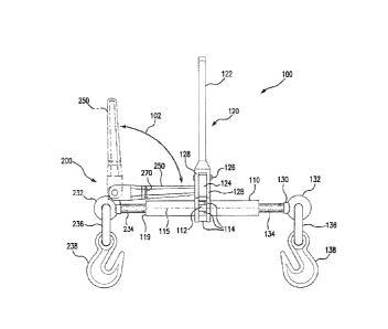
[0010] FIG. 1 is an elevation view of the ratchet load binder of the present
invention in the
extended position;
[0011] FIG. 2 is an exploded view of the stabilized attachment assembly of the
present
invention;
[0012] FIG. 2A is cut-away top view of the stabilized attachment assembly of
the present
invention;
[0013] FIG. 2B is an elevation view of the stabilized attachment assembly of
the present
invention;
[0014] FIG. 3 is an elevation view of the ratchet load binder of the present
invention,
partially cut-away;
[0015] FIG. 4 is an illustration of the use of the present invention; and
[0016] FIG. 5 is an elevation view of the ratchet load binder of the present
invention in the
retracted position.
DETAILED DESCRIPTION OF THE PREFERRED EMBODIMENTS
[0017] Referring to Figs. 1-5, there is shown ratchet load binder 100 with a
stabilized
attachment assembly 200 providing an improved tensioning device for chains 10
and 14 used
in load securement and tie down systems. As will be described in following
paragraphs,
ratchet load binder 100 allows a user 50 to control rotational force that is
applied to the
attachment assembly 200 by the rotation of the tubular member 110 of the
ratchet load binder
100 by operation of the ratchet handle 122.
[0018] Referring specifically to Figs. 1 and 3, there is shown ratchet load
binder 100 which is
typically used to tighten chains that secure loads to transporting vehicles.
To that end, ratchet
load binder 100 includes an attachment member 130 and an attachment assembly
200
respectively threadedly engaged in opposing open ends 116 of the
longitudinally extended
tubular member 110. Tubular member 110 has a ratchet spur gear 112 coupled
thereto and
disposed concentric to the longitudinal axis 115 of the tubular member 110.
Ratchet spur
gear 112 has a plurality of gear teeth 114 and may be mounted centrally with
respect to the
longitudinal extent of the tubular member 110 or adjacent an end portion
thereof. The ratchet
spur gear 112 is engaged by a double acting ratchet handle assembly 120 that
is rotatably
coupled to the tubular member 110 and is rotatable about the ratchet spur gear
112 to provide
rotary motion to the tubular member 110.
4
CA 2992627 2018-01-23
[0019] Ratchet handle assembly 120 includes a ratchet handle 122 that extends
transversely
with respect to the axis 115 of tubular member110, and a spring biased double
acting pawl
124 pivotally coupled to the ratchet handle 122. The double acting pawl 124 is
pivotally
coupled to the ratchet handle 122 between a pair of arms 128 thereof by a pin,
rivet or bolt
126 and spring biased by a compression spring and detent ball, as is typical
(not shown). The
ratchet handle 122, spring biased double acting pawl 124 and ratchet spur gear
112 together
define the ratchet assembly of the ratchet load binder 100. The ratchet handle
assembly 120
is conventional and is of the type commonly used in ratchet load binders and
thereby well
known in the art. Accordingly, the structure of ratchet handle assembly 120
need not be
described in any greater detail than that provided above.
[0020] The tubular member 110 has internal threads 117, 118, respectively, in
the open ends
116. The threads 117 and 118 may be acme or square threads, with one end
having left hand
threads 117, for example, and the opposing end having right hand threads. It
is not important
which end has the left handed or right handed threads, only that the opposing
ends 116 have
oppositely directed threads so that the attachment member 130 and attachment
assembly 200
are linearly displaced relative to the tubular member in common, into or out
from the open
ends 116. The attachment member 130 and attachment assembly 200 are moved
towards or
away from one another by rotation of the tubular member 110 to tighten or
loosen the chain
securing a load to a vehicle, as a function of the direction of rotation of
the tubular member
110.
[0021] The exemplary attachment member 130 shown in Figs 1 and 3-5 is shown as
an eye
bolt, to which a hook 138 is connected via a link 136. Alternately, a hook
bolt or clevis jaw
may be used in place of the combined eye bolt, link and hook. Attachment
member 130 has
an eye portion 132 having a substantially annular closed contour disposed at
one end thereof.
As a means for connection to a chain, the eye portion 132 is coupled to the
hook 138 by the
intervening link 136. The intervening link 136 can be eliminated by coupling a
clevis type
hook (not shown), shackle or the like, directly to the eye bolt. Attachment
member 130
further has a longitudinally extended threaded shaft portion 134 at the
opposing end thereof.
The threads of the threaded shaft portion 134 are complementary to the threads
117 of the
corresponding open end 116 into which it is engaged, with respect to the
direction and type of
threads.
[0022] Referring additionally to Fig. 2, there is shown, an exploded view of
attachment
assembly 200. Attachment assembly 200 includes an attachment member 230 and a
lever
arm 250 coupled to the attachment member 230. Attachment member 230 is
illustrated as an
5
CA 2992627 2018-01-23
eye bolt to which a hook 238 is connected through an intervening link 236. As
in the
attachment member 130, a hook bolt or clevis jaw may be used in place of the
combined eye
bolt, link and hook. Attachment member 230 has an eye portion 232 having a
substantially
annular closed contour disposed at one end thereof. As a means for connection
to a chain, the
eye portion 232 is coupled to the hook 238 by the intervening link 236.
Hereto, the
intervening link 236 can be eliminated by coupling a clevis type hook (not
shown), shackle or
the like, directly to the eye portion 232. Attachment member 230 has a
longitudinal axis 205
and an axially extended threaded shaft portion 234 at the opposing end
thereof. The threads
of the threaded shaft portion 234 are complementary to the threads 118 of the
corresponding
open end 116 into which it is engaged, with respect to the direction and type
of threads.
[0023] While the lever arm 250 may be coupled to attachment member 230 by
other means,
the exemplary attachment assembly 200 includes a protruding boss or tab 240 as
an
attachment site for lever arm 250. The protruding tab 240 can be forged,
stamped, welded or
otherwise mechanically attached to the attachment member 230. The protruding
tab 240 may
be affixed to the eye portion 232, as shown, or adjacent thereto and extend in
a direction
transverse to the longitudinal axis 205 of the attachment member 230. As
shown, the lever
arm 250 is coupled to the protruding tab 240, allowing a user to hold the
lever arm 250 with
one hand while using their other hand to operate the ratchet handle 122. The
lever arm 250 is
formed of a material having sufficient size and strength for the purpose to
which it is
employed in ratchet load binder 100. While lever arm 250 may be fixedly
attached to
protruding tab 240, or alternately directly affixing the lever arm 250 to the
attachment
member 230 or integrally forming it therewith, thereby eliminating the
protruding tab 240, it
is believed that greater utilitarian value is achieved with lever arm 250
being reconfigurablely
coupled to the protruding tab 240, as by a pivotal coupling. The lever arm 250
may be
reconfigurablely coupled to the attachment member 230 by being removably
attached to the
attachment member 230, which is configured so that the lever arm 250 can be
selectively
coupled to the attachment member 230 in one of multiple orientations. In this
manner the
lever arm 250 can be reconfigurable in, for example, either a use position
substantially
orthogonal to the longitudinal axis 115 of the tubular member 110, or a
storage position
substantially parallel to the longitudinal axis 115 of the tubular member 110.
The lever arm
250 may be of a fixed length chosen to provide the necessary mechanical
advantage required
to stabilize the attachment assembly 200, and thereby the ratchet load binder
100, or an
adjustable length lever arm attached to the attachment member 230.
[0024] For pivotal coupling of the lever arm 250, the protruding tab 240 may
be configured
6
CA 2992627 2018-01-23
with a pair of oppositely directed trunnion posts (not shown) or other means
of pivotally
attaching a lever arm or handle. The protrusion tab 240 may also have one or
more holes,
detents and/or grooves for the attachment and function of the lever arm 250
thereto with a
pin, such as the pin 260, a bolt, a rivet, or other like means. In the
exemplary attachment
assembly 200, the protrusion tab 240 has a pivot hole 244 through which the
pin 260 passes
to pivotally secure the lever arm 250 to the protrusion tab 240. For
attachment of lever arm
250 to protrusion tab 240, lever arm 250 has a coupling portion 255 at a
distal end thereof
with a handle portion 251 extending from the coupling portion 255. In the
exemplary
attachment assembly 200 shown in the Figs 2, 2A and 2B, the coupling portion
255 is
bifurcated into a pair of leg portions 254, spaced from one another by a
receiving space 258.
A cavity 256 may be formed in an end wall 253 of the coupling portion 255 of
lever arm 250
and is in open communication with the receiving space 258. The cavity 256
receives a detent
spring 262 and a detent ball 264 therein.
[0025] The pair of leg portions 252 have respective aligned through holes 254
and align with
the pivot hole 244 of protrusion tab 240 when received in the receiving space
258. The lever
arm 250 is thereby pivotally coupled to the protrusion tab 240 by the pin 260
being passed
through the pair of through holes 254 and the pivot hole 244. The pin 260 is
secured by a
cotter pin, such as the split pin 268, as is illustrated, or a hairpin cotter
pin, or bowtie cotter
pin or a like fastener passed through the cross hole 266 formed through the
pin 260. A bolt,
rivet or other shaft-like member may be substituted for pin 260 to provide a
pivotal coupling
between the leg portions 252 and the protrusion tab 240.
[0026] Protrusion tab 240 has an asymmetrical contour at the distal end
thereof. The top
corner 242 has a large radius, a radius that is sufficient to provide
clearance between the end
surface 245 of the protrusion tab 240 and the end wall 253 as the lever arm
250 is pivoted
between positions substantially orthogonal to the longitudinal axis 205 of the
attachment
member 230 and substantially parallel thereto, as indicated by the directional
arrow 102. The
radiused corner 242 thereby facilitates the angular displacement of the of the
lever arm 250
about the pin 260 in a direction toward the threaded shaft portion 234. The
opposing top
corner 246, adjacent the eye portion 232, has a substantially right angle
contour and may
have a small chamfered edge or small radiused edge. The substantially right
angle contour of
the top corner 246 acts to block pivotal displacement of the lever arm 250 in
the direction of
the eye portion 232, as the end surface 245 adjacent the top corner 246
contacts the end wall
253 when the lever arm 250 is moved toward the eye portion 232.
[0027] The end surface 245 of protrusion tab 240 may have at least one detent
receiving
7
CA 2992627 2018-01-23
recess 246, 247 formed therein to releasably hold the lever arm in a
particular position with
respect to the longitudinal axis 205 of the attachment member 230, which axis
is coaxial with
the longitudinal axis 115 of the tubular member 110. Thus, when the lever arm
250 is
pivotally displaced to a position where the spring biased detent ball 264 is
aligned with a
detent receiving recess 246, 247, the spring bias force of spring 262 applied
to detent ball 264
causes detent ball 264 to be partially inserted into the recess 246, 247. By
that arrangement,
the lever arm 250 is held in that position until sufficient displacement force
is applied to the
lever arm 250 to overcome the spring bias force applied to the detent ball 264
by the spring
262. A detent receiving recess 246 may be formed in the end surface 245 at a
position
between the top corners 242 and 246 to releasably hold the handle in an open
position, an
upright orientation that is substantially orthogonal to the longitudinal axis
115 of the of the
tubular member 110. Alternately, or in addition to the detent receiving recess
246, a detent
receiving recess 247 may be formed in end surface 245 on a side of the
protrusion tab 240
facing the threaded shaft portion 234 to releasably hold the handle in a
measurement/storage
position, substantially parallel to the longitudinal axis 115 of the tubular
member 110. Other
tensioning means can be employed in place of the spring biased detent ball to
releasably
retain lever member 250 in desired positions or control the pivotal movement
of the lever
member 250.
[0028] Referring back to Fig. 1, a safety feature is shown in that the lever
arm 250 can be
provided with indicia 270. The indicia 270 may be stamped, inscribed, cast or
otherwise
permanently formed in or on the lever arm 250, or provided by a label or
printed, painted or
otherwise marked on lever arm 250. Indicia 270 may be represented by any
symbol or
geometric form useable as a reference mark to be aligned with the
corresponding end edge
119 of tubular member 110. Alignment of indicia 270 with the end edge 119 of
tubular
member 110, when the lever arm 250 is in the measurement/storage position,
indicates an
extended length of attachment member 230 that still provides a safe minimum
engagement of
the threaded shaft portion 234 with the threads 118 formed in the
corresponding open end
116 of tubular member 110. The extent that the exposed portion of the threaded
shaft
portion 234 extends from the end 119 of tubular member 110 provides a visual
reference for
comparison with the extent that the threaded shaft portion 134 of attachment
member 130 is
exposed from the opposing end of tubular member 110 to indicate its safe
minimum
engagement with the threads 117 formed in the corresponding open end 116 of
tubular
member 110.
[0029] For storage and as a further safety feature, as illustrated in Fig. 5,
the attachment
8
CA 2992627 2018-01-23
member 130 and attachment assembly 200 are each threaded a substantial amount
into the
respective open ends 116 of tubular member 110 and the lever arm 250 is
rotated to the
measurement/storage position, as indicated by the directional arrow 102. For
storage,
attachment member 130 and attachment assembly 200 would typically each be
fully threaded
into the respective open ends 116 of tubular member 110. The ability to rotate
the lever arm
250 to the measurement/storage position convenient provides for storage of
ratchet load
binder 100 in essentially the same space as that used for storage of
conventional ratchet load
binders. With respect to safety, subsequent to the chain to which ratchet load
binder 100 is
coupled being tightened, the attachment assembly 200 is rotated relative to
the tubular
member 110 about the axis 205 to position the lever arm 250 adjacent to and
aligned position
with the ratchet handle 122, as shown in Fig. 1. The lever arm 250 is then
rotated to the
measurement/storage position. In the measurement/storage position, the lever
arm 250
blocks the rotational movement of ratchet handle 122 and thereby serves as a
rotational lock
for ratchet load binder 100.
[0030] Referring specifically to Figs. 1 and 4, an example of the use of
ratchet load binder
100 is shown. Subsequent to the attachment member 130 and attachment assembly
200 being
moved outward from the tubular member 110 while maintaining a safe minimum
engagement
of the threaded portions 134 and 234 thereof, as described above, ratchet load
binder 100 is
ready to be employed for tightening the chain 14 securing a load 20 to a
transport vehicle 30.
The hook 138, which may be a grab hook, is connected to the transport vehicle
30 by a short
length of chain 10 and hook 12 that connects to an anchor point, such as the
tie loop or strap
32. Transport vehicles may alternatively have lashing rings or tie down rails
as anchor points
to which the hook 12 connects or the chain 10 loops through with the hook 12
being
connected to a link thereof. The hook 138 of ratchet load bonder 100 is
connected to a link of
the chain 10 and the load binder hook 238, which may be a grab hook, is
connected to the
chain 14 that extends to the load 20, illustrated as a vehicle, but may be any
type load
requiring the use of tie down chains,
[0031] When moving the attachment members 130 and 230 towards or away from
each by
the rotary motion of the tubular member 110, the attachment members 130 and
230 would
tend to rotate with the tubular member 110, which tendency is increased with
ordinary usage
as the threads become rusted, fouled or damaged. The Attachment member 130 is
stabilized
against such rotation by the short length of chain 10 which has little
torsional play. The
attachment member 230 is stabilized against rotation by use of the lever arm
250, which by
virtue of the long length of chain and being initially slack has significant
torsional play and
9
CA 2992627 2018-01-23
would otherwise rotate. The user 50 orients the lever arm in the open position
and holds the
lever arm 250 with one hand while reciprocatively operating the ratchet handle
122, as
indicated by the directional arrow 104, with the user's other hand. In that
manner, the user 50
is able to stabilize the attachment member 230 against rotation as the tubular
member is
rotated.
[0032] The descriptions above are intended to illustrate possible
implementations of the
present invention and are not restrictive. While this invention has been
described in
connection with specific forms and embodiments thereof, it will be appreciated
that various
modifications other than those discussed above may be resorted to without
departing from the
spirit or scope of the invention. Such variations, modifications, and
alternatives will become
apparent to the skilled artisan upon review of the disclosure. For example,
functionally
equivalent elements may be substituted for those specifically shown and
described, and
certain features may be used independently of other features, and in certain
cases, particular
locations of elements may be reversed or interposed, all without departing
from the spirit or
scope of the invention as defined in the appended Claims. The scope of the
invention should
therefore be determined with reference to the description above, the appended
claims and
drawings, along with their full range of equivalents.
CA 2992627 2018-01-23