Note: Descriptions are shown in the official language in which they were submitted.
- 1 -
FIBROUS BARRIERS AND DEPLOYMENT
IN SUBTERRANEAN ViMMEAS
This application is divided from Canadian Patent
Application Serial No. 2,928,237 filed on April 26, 2016.
BACKGROUND
This disclosure relates generally to equipment utilized
and operations performed in conjunction with a subterranean
well and, in one example described below, more particularly
provides for fibrous barriers and their deployment in wells.
It can be beneficial to be able to control how and where
fluid flows in a well. For example, it may be desirable in
some circumstances to be able to prevent fluid from flowing
into a particular formation zone. As another example, it may
be desirable in some circumstances to cause fluid to flow into
a particular formation zone, instead of into another formation
zone. As yet another example, it may be desirable to
temporarily prevent fluid from flowing through a passage of a
well tool. Therefore, it will be readily appreciated that
improvements are continually needed in the art of controlling
fluid flow in wells.
SUMMARY
Accordingly, there is described a fibrous plugging device
for use in a subterranean well, the device comprising: a body
including fibers and a retainer material, wherein the retainer
material retains a shape of the body, and wherein the fibers
are treated with a release agent that repels the retainer
material.
CA 2992763 2018-01-23
- 2 -
BRIEF DESCRIPTION OF THE DRAWINGS
FIG. 1 is a representative partially cross-sectional view
of an example of a well system and associated method which can
embody principles of this disclosure.
FIGS. 2A-D are enlarged scale representative partially
cross-sectional views of steps in an example of a re-
completion method that may be practiced with the system of
FIG. 1.
FIGS. 3A-D are representative partially cross-sectional
views of steps in another example of a method that may be
practiced with the system of FIG. 1.
FIGS. 4A & B are enlarged scale representative
elevational views of examples of a flow conveyed device that
may be used in the system and methods of FIGS. 1-3D, and which
can embody the principles of this disclosure.
FIG. 5 is a representative elevational view of another
example of the flow conveyed device.
FIGS. 6A & B are representative partially cross-sectional
views of the flow conveyed device in a well, the device being
conveyed by flow in FIG. 6A, and engaging a casing opening in
FIG. 6B.
FIGS. 7-9 are representative elevational views of
examples of the flow conveyed device with a retainer.
FIG. 10 is a representative cross-sectional view of an
example of a deployment apparatus and method that can embody
the principles of this disclosure.
CA 2992763 2018-01-23
- 3 -
FIG. 11 is a representative schematic view of another
example of a deployment apparatus and method that can embody
the principles of this disclosure.
FIGS. 12 & 13 are representative cross-sectional views of
additional examples of the flow conveyed device.
FIG. 14 is a representative cross-sectional view of a
well tool that may be operated using the flow conveyed device.
DETAILED DESCRIPTION
Representatively illustrated in FIG. 1 is a system 10 for
use with a well, and an associated method, which can embody
principles of this disclosure. However, it should be clearly
understood that the system 10 and method are merely one
example of an application of the principles of this disclosure
in practice, and a wide variety of other examples are
possible. Therefore, the scope of this disclosure is not
limited at all to the details of the system 10 and method
described herein and/or depicted in the drawings.
In the FIG. 1 example, a tubular string 12 is conveyed
into a wellbore 14 lined with casing 16 and cement 18.
Although multiple casing strings would typically be used in
actual practice, for clarity of illustration only one casing
string 16 is depicted in the drawings.
Although the wellbore 14 is illustrated as being
vertical, sections of the wellbore could instead be horizontal
or otherwise inclined relative to vertical. Although the
wellbore 14 is completely cased and cemented as depicted in
FIG. 1, any sections of the wellbore in which operations
described in more detail below are performed could be uncased
CA 2992763 2018-01-23
- 4 -
or open hole. Thus, the scope of this disclosure is not
limited to any particular details of the system 10 and method.
The tubular string 12 of FIG. 1 comprises coiled tubing
20 and a bottom hole assembly 22. As used herein, the term
"coiled tubing" refers to a substantially continuous tubing
that is stored on a spool or reel 24. The reel 24 could be
mounted, for example, on a skid, a trailer, a floating vessel,
a vehicle, etc., for transport to a wellsite. Although not
shown in FIG. 1, a control room or cab would typically be
provided with instrumentation, computers, controllers,
recorders, etc., for controlling equipment such as an injector
26 and a blowout preventer stack 28.
As used herein, the term "bottom hole assembly" refers to
an assembly connected at a distal end of a tubular string in a
well. It is not necessary for a bottom hole assembly to be
positioned or used at a "bottom" of a hole or well.
When the tubular string 12 is positioned in the wellbore
14, an annulus 30 is formed radially between them. Fluid,
slurries, etc., can be flowed from surface into the annulus 30
via, for example, a casing valve 32. One or more pumps 34 may
be used for this purpose. Fluid can also be flowed to surface
from the wellbore 14 via the annulus 30 and valve 32.
Fluid, slurries, etc., can also be flowed from surface
into the wellbore 14 via the tubing 20, for example, using one
or more pumps 36. Fluid can also be flowed to surface from the
wellbore 14 via the tubing 20.
In the further description below of the examples of FIGS.
2A-14, one or more flow conveyed devices are used to block or
CA 2992763 2018-01-23
- 5 -
plug openings in the system 10 of FIG. 1. However, it should
be clearly understood that these methods and the flow conveyed
device may be used with other systems, and the flow conveyed
device may be used in other methods in keeping with the
principles of this disclosure.
The example methods described below allow existing fluid
passageways to be blocked permanently or temporarily in a
variety of different applications. Certain flow conveyed
device examples described below are made of a fibrous material
and may comprise a central body, a "knot" or other enlarged
geometry.
The devices may be conveyed into the passageways or leak
paths using pumped fluid. Fibrous material extending outwardly
from a body of a device can "find" and follow the fluid flow,
pulling the enlarged geometry or fibers into a restricted
portion of a flow path, causing the enlarged geometry and
additional strands to become tightly wedged into the flow
path, thereby sealing off fluid communication.
The devices can be made of degradable or non-degradable
materials. The degradable materials can be either self-
degrading, or can require degrading treatments, such as, by
exposing the materials to certain acids, certain base
compositions, certain chemicals, certain types of radiation
(e.g., electromagnetic or "nuclear"), or elevated temperature.
The exposure can be performed at a desired time using a form
of well intervention, such as, by spotting or circulating a
fluid in the well so that the material is exposed to the
fluid.
CA 2992763 2018-01-23
- 6 -
In some examples, the material can be an acid degradable
material (e.g., nylon, etc.), a mix of acid degradable
material (for example, nylon fibers mixed with particulate
such as calcium carbonate), self-degrading material (e.g.,
poly-lactic acid (PLA), poly-glycolic acid (PGA), etc.),
material that degrades by galvanic action (such as, magnesium
alloys, aluminum alloys, etc.), a combination of different
self-degrading materials, or a combination of self-degrading
and non-self-degrading materials.
Multiple materials can be pumped together or separately.
For example, nylon and calcium carbonate could be pumped as a
mixture, or the nylon could be pumped first to initiate a
seal, followed by calcium carbonate to enhance the seal.
In certain examples described below, the device can be
made of knotted fibrous materials. Multiple knots can be used
with any number of loose ends. The ends can be frayed or un-
frayed. The fibrous material can be rope, fabric, metal wool,
cloth or another woven or braided structure.
The device can be used to block open sleeve valves,
perforations or any leak paths in a well (such as, leaking
connections in casing, corrosion holes, etc.). Any opening or
passageway through which fluid flows can be blocked with a
suitably configured device. For example, an intentionally or
inadvertently opened rupture disk, or another opening in a
well tool, could be plugged using the device.
In one example method described below, a well with an
existing perforated zone can be re-completed. Devices (either
degradable or non-degradable) are conveyed by flow to plug all
existing perforations.
CA 2992763 2018-01-23
- 7 -
The well can then be re-completed using any desired
completion technique. If the devices are degradable, a
degrading treatment can then be placed in the well to open up
the plugged perforations (if desired).
In another example method described below, multiple
formation zones can be perforated and fractured (or otherwise
stimulated, such as, by acidizing) in a single trip of the
bottom hole assembly 22 into the well. In the method, one zone
is perforated, the zone is stimulated, and then the perforated
zone is plugged using one or more devices.
These steps are repeated for each additional zone, except
that a last zone may not be plugged. All of the plugged zones
are eventually unplugged by waiting a certain period of time
(if the devices are self-degrading), by applying an
appropriate degrading treatment, or by mechanically removing
the devices.
Referring specifically now to FIGS. 2A-D, steps in an
example of a method in which the bottom hole assembly 22 of
FIG. 1 can be used in re-completing a well are
representatively illustrated. In this method (see FIG. 2A),
the well has existing perforations 38 that provide for fluid
communication between an earth formation zone 40 and an
interior of the casing 16. However, it is desired to re-
complete the zone 40, in order to enhance the fluid
communication.
Referring additionally now to FIG. 2B, the perforations
38 are plugged, thereby preventing flow through the
perforations into the zone 40. Plugs 42 in the perforations
can be flow conveyed devices, as described more fully below.
CA 2992763 2018-01-23
- 8 -
In that case, the plugs 42 can be conveyed through the casing
16 and into engagement with the perforations 38 by fluid flow
44.
Referring additionally now to FIG. 2C, new perforations
46 are formed through the casing 16 and cement 18 by use of an
abrasive jet perforator 48. In this example, the bottom hole
assembly 22 includes the perforator 48 and a circulating valve
assembly 50. Although the new perforations 46 are depicted as
being formed above the existing perforations 38, the new
perforations could be formed in any location in keeping with
the principles of this disclosure.
Note that other means of providing perforations 46 may be
used in other examples. Explosive perforators, drills, etc.,
may be used if desired. The scope of this disclosure is not
limited to any particular perforating means, or to use with
perforating at all.
The circulating valve assembly 50 controls flow between
the coiled tubing 20 and the perforator 48, and controls flow
between the annulus 30 and an interior of the tubular string
12. Instead of conveying the plugs 42 into the well via flow
44 through the interior of the casing 16 (see FIG. 2B), in
other examples the plugs could be deployed into the tubular
string 12 and conveyed by fluid flow 52 through the tubular
string prior to the perforating operation. In that case, a
valve 54 of the circulating valve assembly 50 could be opened
to allow the plugs 42 to exit the tubular string 12 and flow
into the interior of the casing 16 external to the tubular
string.
CA 2992763 2018-01-23
- 9 -
Referring additionally now to FIG. 2D, the zone 40 has
been fractured by applying increased pressure to the zone
after the perforating operation. Enhanced fluid communication
is now permitted between the zone 40 and the interior of the
casing 16.
Note that fracturing is not necessary in keeping with the
principles of this disclosure. A zone could be stimulated (for
example, by acidizing) with or without fracturing. Thus,
although fracturing is described for certain examples, it
should be understood that other types of stimulation
treatments, in addition to or instead of fracturing, could be
performed.
In the FIG. 2D example, the plugs 42 prevent the pressure
applied to fracture the zone 40 via the perforations 46 from
leaking into the zone via the perforations 38. The plugs 42
may remain in the perforations 38 and continue to prevent flow
through the perforations, or the plugs may degrade, if
desired, so that flow is eventually permitted through the
perforations.
In other examples, fractures may be formed via the
existing perforations 38, and no new perforations may be
formed. In one technique, pressure may be applied in the
casing 16 (e.g., using the pump 34), thereby initially
fracturing the zone 40 via some of the perforations 38 that
receive most of the fluid flow 44. After the initial
fracturing of the zone 40, and while the fluid is flowed
through the casing 16, plugs 42 can be released into the
casing, so that the plugs seal off those perforations 38 that
are receiving most of the fluid flow.
CA 2992763 2018-01-23
- 10 -
In this way, the fluid 44 will be diverted to other
perforations 38, so that the zone 40 will also be fractured
via those other perforations 38. The plugs 42 can be released
into the casing 16 continuously or periodically as the
fracturing operation progresses, so that the plugs gradually
seal off all, or most, of the perforations 38 as the zone 40
is fractured via the perforations. That is, at each point in
the fracturing operation, the plugs 42 will seal off those
perforations 38 through which most of the fluid flow 44
passes, which are the perforations via which the zone 40 has
been fractured.
Referring additionally now to FIGS. 3A-D, steps in
another example of a method in which the bottom hole assembly
22 of FIG. 1 can be used in completing multiple zones 40a-c of
a well are representatively illustrated. The multiple zones
40a-c are each perforated and fractured during a single trip
of the tubular string 12 into the well.
In FIG. 3A, the tubular string 12 has been deployed into
the casing 16, and has been positioned so that the perforator
48 is at the first zone 40a to be completed. The perforator 48
is then used to form perforations 46a through the casing 16
and cement 18, and into the zone 40a.
In FIG. 3B, the zone 40a has been fractured by applying
increased pressure to the zone via the perforations 46a. The
fracturing pressure may be applied, for example, via the
annulus 30 from the surface (e.g., using the pump 34 of FIG.
1), or via the tubular string 12 (e.g., using the pump 36 of
FIG. 1). The scope of this disclosure is not limited to any
CA 2992763 2018-01-23
- 11 -
particular fracturing means or technique, or to the use of
fracturing at all.
After fracturing of the zone 40a, the perforations 46a
are plugged by deploying plugs 42a into the well and conveying
them by fluid flow into sealing engagement with the
perforations. The plugs 42a may be conveyed by flow 44 through
the casing 16 (e.g., as in FIG. 2B), or by flow 52 through the
tubular string 12 (e.g., as in FIG. 2C).
The tubular string 12 is repositioned in the casing 16,
so that the perforator 48 is now located at the next zone 40b
to be completed. The perforator 48 is then used to form
perforations 46b through the casing 16 and cement 18, and into
the zone 40b. The tubular string 12 may be repositioned before
or after the plugs 42a are deployed into the well.
In FIG. 3C, the zone 40b has been fractured by applying
increased pressure to the zone via the perforations 46b. The
fracturing pressure may be applied, for example, via the
annulus 30 from the surface (e.g., using the pump 34 of FIG.
1), or via the tubular string 12 (e.g., using the pump 36 of
FIG. 1).
After fracturing of the zone 40b, the perforations 46b
are plugged by deploying plugs 42b into the well and conveying
them by fluid flow into sealing engagement with the
perforations. The plugs 42b may be conveyed by flow 44 through
the casing 16, or by flow 52 through the tubular string 12.
The tubular string 12 is repositioned in the casing 16,
so that the perforator 48 is now located at the next zone 40c
to be completed. The perforator 48 is then used to form
CA 2992763 2018-01-23
- 12 -
perforations 46c through the casing 16 and cement 18, and into
the zone 40c. The tubular string 12 may be repositioned before
or after the plugs 42b are deployed into the well.
In FIG. 3D, the zone 40c has been fractured by applying
increased pressure to the zone via the perforations 46c. The
fracturing pressure may be applied, for example, via the
annulus 30 from the surface (e.g., using the pump 34 of FIG.
1), or via the tubular string 12 (e.g., using the pump 36 of
FIG. 1).
The plugs 42a,b are then degraded and no longer prevent
flow through the perforations 46a,b. Thus, as depicted in FIG.
3D, flow is permitted between the interior of the casing 16
and each of the zones 40a-c.
The plugs 42a,b may be degraded in any manner. The plugs
42a,b may degrade in response to application of a degrading
treatment, in response to passage of a certain period of time,
or in response to exposure to elevated downhole temperature.
The degrading treatment could include exposing the plugs 42a,b
to a particular type of radiation, such as electromagnetic
radiation (e.g., light having a certain wavelength or range of
wavelengths, gamma rays, etc.) or "nuclear" particles (e.g.,
gamma, beta, alpha or neutron).
The plugs 42a,b may degrade by galvanic action or by
dissolving. The plugs 42a,b may degrade in response to
exposure to a particular fluid, either naturally occurring in
the well (such as water or hydrocarbon fluid), or introduced
therein (such as a fluid having a particular pH).
CA 2992763 2018-01-23
- 13 -
Note that any number of zones may be completed in any
order in keeping with the principles of this disclosure. The
zones 40a-c may be sections of a single earth formation, or
they may be sections of separate formations. Although the
perforations 46c are not described above as being plugged in
the method, the perforations 46c could be plugged after the
zone 40c is fractured or otherwise stimulated (e.g., to verify
that the plugs are indeed preventing flow from the casing 16
to the zones 40a-c).
In other examples, the plugs 42 may not be degraded. The
plugs 42 could instead be mechanically removed, for example,
by milling or otherwise cutting the plugs 42 away from the
perforations. In any of the method examples described above,
after the fracturing operation(s) are completed, the plugs 42
can be milled off or otherwise removed from the perforations
38, 46, 46a,b without dissolving, melting, dispersing or
otherwise degrading a material of the plugs.
In some examples, the plugs 42 can be mechanically
removed, without necessarily cutting the plugs. A tool with
appropriate gripping structures (such as a mill or another
cutting or grabbing device) could grab the plugs 42 and pull
them from the perforations.
Referring additionally now to FIG. 4A, an example of a
flow conveyed device 60 that can incorporate the principles of
this disclosure is representatively illustrated. The device 60
may be used for any of the plugs 42, 42a,b in the method
examples described above, or the device may be used in other
methods.
CA 2992763 2018-01-23
- 14 -
The device 60 example of FIG. 4A includes multiple fibers
62 extending outwardly from an enlarged body 64. As depicted
in FIG. 4A, each of the fibers 62 has a lateral dimension
(e.g., a thickness or diameter) that is substantially smaller
than a size (e.g., a thickness or diameter) of the body 64.
The body 64 can be dimensioned so that it will
effectively engage and seal off a particular opening in a
well. For example, if it is desired for the device 60 to seal
off a perforation in a well, the body 64 can be formed so that
it is somewhat larger than a diameter of the perforation. If
it is desired for multiple devices 60 to seal off multiple
_
openings having a variety of dimensions (such as holes caused
by corrosion of the casing 16), then the bodies 64 of the
devices can be formed with a corresponding variety of sizes.
In the FIG. 4A example, the fibers 62 are joined together
(e.g., by braiding, weaving, cabling, etc.) to form lines 66
that extend outwardly from the body 64. In this example, there
are two such lines 66, but any number of lines (including one)
may be used in other examples.
The lines 66 may be in the form of one or more ropes, in
which case the fibers 62 could comprise frayed ends of the
rope(s). In addition, the body 64 could be formed by one or
more knots in the rope(s). In some examples, the body 64 can
comprise a fabric or cloth, the body could be formed by one or
more knots in the fabric or cloth, and the fibers 62 could
extend from the fabric or cloth.
In other examples, the device 60 could comprise a single
sheet of material, or multiple strips of sheet material. The
device 60 could comprise one or more films. The body 64 and
CA 2992763 2018-01-23
- 15 -
lines 66 may not be made of the same material, and the body
and/or lines may not be made of a fibrous material.
In the FIG. 4A example, the body 64 is formed by a double
overhand knot in a rope, and ends of the rope are frayed, so
that the fibers 62 are splayed outward. In this manner, the
fibers 62 will cause significant fluid drag when the device 60
is deployed into a flow stream, so that the device will be
effectively "carried" by, and "follow," the flow.
However, it should be clearly understood that other types
of bodies and other types of fibers may be used in other
examples. The body 64 could have other shapes, the body could
be hollow or solid, and the body could be made up of one or
multiple materials. The fibers 62 are not necessarily joined
by lines 66, and the fibers are not necessarily formed by
fraying ends of ropes or other lines. The body 64 is not
necessarily centrally located in the device 60 (for example,
the body could be at one end of the lines 66). Thus, the scope
of this disclosure is not limited to the construction,
configuration or other details of the device 60 as described
herein or depicted in the drawings.
Referring additionally now to FIG. 4B, another example of
the device 60 is representatively illustrated. In this
example, the device 60 is formed using multiple braided lines
66 of the type known as "mason twine." The multiple lines 66
are knotted (such as, with a double or triple overhand knot or
other type of knot) to form the body 64. Ends of the lines 66
are not necessarily be frayed in these examples, although the
lines do comprise fibers (such as the fibers 62 described
above).
CA 2992763 2018-01-23
- 16 -
Referring additionally now to FIG. 5, another example of
the device 60 is representatively illustrated. In this
example, four sets of the fibers 62 are joined by a
corresponding number of lines 66 to the body 64. The body 64
is formed by one or more knots in the lines 66.
FIG. 5 demonstrates that a variety of different
configurations are possible for the device 60. Accordingly,
the principles of this disclosure can be incorporated into
other configurations not specifically described herein or
depicted in the drawings. Such other configurations may
include fibers joined to bodies without use of lines, bodies
formed by techniques other than knotting, etc.
Referring additionally now to FIGS. 6A & B, an example of
a use of the device 60 of FIG. 4 to seal off an opening 68 in
a well is representatively illustrated. In this example, the
opening 68 is a perforation formed through a sidewall 70 of a
tubular string 72 (such as, a casing, liner, tubing, etc.).
However, in other examples the opening 68 could be another
type of opening, and may be formed in another type of
structure.
The device 60 is deployed into the tubular string 72 and
is conveyed through the tubular string by fluid flow 74. The
fibers 62 of the device 60 enhance fluid drag on the device,
so that the device is influenced to displace with the flow 74.
Since the flow 74 (or a portion thereof) exits the
tubular string 72 via the opening 68, the device 60 will be
influenced by the fluid drag to also exit the tubular string
via the opening 68. As depicted in FIG. 6B, one set of the
fibers 62 first enters the opening 68, and the body 64
CA 2992763 2018-01-23
- 17 -
follows. However, the body 64 is appropriately dimensioned, so
that it does not pass through the opening 68, but instead is
lodged or wedged into the opening. In some examples, the body
64 may be received only partially in the opening 68, and in
other examples the body may be entirely received in the
opening.
The body 64 may completely or only partially block the
flow 74 through the opening 68. If the body 64 only partially
blocks the flow 74, any remaining fibers 62 exposed to the
flow in the tubular string 72 can be carried by that flow into
any gaps between the body and the opening 68, so that a
combination of the body and the fibers completely blocks flow
through the opening.
In another example, the device 60 may partially block
flow through the opening 68, and another material (such as,
calcium carbonate, PLA or PGA particles) may be deployed and
conveyed by the flow 74 into any gaps between the device and
the opening, so that a combination of the device and the
material completely blocks flow through the opening.
The device 60 may permanently prevent flow through the
opening 68, or the device may degrade to eventually permit
flow through the opening. If the device 60 degrades, it may be
self-degrading, or it may be degraded in response to any of a
variety of different stimuli. Any technique or means for
degrading the device 60 (and any other material used in
conjunction with the device to block flow through the opening
68) may be used in keeping with the scope of this disclosure.
In other examples, the device 60 may be mechanically
removed from the opening 68. For example, if the body 64 only
CA 2992763 2018-01-23
- 18 -
partially enters the opening 68, a mill or other cutting
device may be used to cut the body from the opening.
Referring additionally now to FIGS. 7-9, additional
examples of the device 60 are representatively illustrated. In
these examples, the device 60 is surrounded by, encapsulated
in, molded in, or otherwise retained by, a retainer 80.
The retainer 80 aids in deployment of the device 60,
particularly in situations where multiple devices are to be
deployed simultaneously. In such situations, the retainer 80
for each device 60 prevents the fibers 62 and/or lines 66 from
becoming entangled with the fibers and/or lines of other
devices.
The retainer 80 could in some examples completely enclose
the device 60. In other examples, the retainer 80 could be in
the form of a binder that holds the fibers 62 and/or lines 66
together, so that they do not become entangled with those of
other devices.
In some examples, the retainer 80 could have a cavity
therein, with the device 60 (or only the fibers 62 and/or
lines 66) being contained in the cavity. In other examples,
the retainer 80 could be molded about the device 60 (or only
the fibers 62 and/or lines 66).
During or after deployment of the device 60 into the
well, the retainer 80 dissolves, melts, disperses or otherwise
degrades, so that the device is capable of sealing off an
opening 68 in the well, as described above. For example, the
retainer 80 can be made of a material 82 that degrades in a
wellbore environment.
CA 2992763 2018-01-23
- 19 -
The retainer material 82 may degrade after deployment
into the well, but before arrival of the device 60 at the
opening 68 to be plugged. In other examples, the retainer
material 82 may degrade at or after arrival of the device 60
at the opening 68 to be plugged. If the device 60 also
comprises a degradable material, then preferably the retainer
material 82 degrades prior to the device material.
The material 82 could, in some examples, melt at elevated
wellbore temperatures. The material 82 could be chosen to have
a melting point that is between a temperature at the earth's
surface and a temperature at the opening 68, so that the
material melts during transport from the surface to the
downhole location of the opening.
The material 82 could, in some examples, dissolve when
exposed to wellbore fluid. The material 82 could be chosen so
that the material begins dissolving as soon as it is deployed
into the wellbore 14 and contacts a certain fluid (such as,
water, brine, hydrocarbon fluid, etc.) therein. In other
examples, the fluid that initiates dissolving of the material
92 could have a certain pH range that causes the material to
dissolve.
Note that it is not necessary for the material 82 to melt
or dissolve in the well. Various other stimuli (such as,
passage of time, elevated pressure, flow, turbulence, etc.)
could cause the material 82 to disperse, degrade or otherwise
cease to retain the device 60. The material 82 could degrade
in response to any one, or a combination, of: passage of a
predetermined period of time in the well, exposure to a
predetermined temperature in the well, exposure to a
CA 2992763 2018-01-23
- 20 -
predetermined fluid in the well, exposure to radiation in the
well and exposure to a predetermined chemical composition in
the well. Thus, the scope of this disclosure is not limited to
any particular stimulus or technique for dispersing or
degrading the material 82, or to any particular type of
material.
In some examples, the material 82 can remain on the
device 60, at least partially, when the device engages the
opening 68. For example, the material 82 could continue to
cover the body 64 (at least partially) when the body engages
and seals off the opening 68. In such examples, the material
82 could advantageously comprise a relatively soft, viscous
and/or resilient material, so that sealing between the device
60 and the opening 68 is enhanced.
Suitable relatively low melting point substances that may
be used for the material 82 can include wax (e.g., paraffin
wax, vegetable wax), ethylene-vinyl acetate copolymer (e.g.,
ELVAX(TM) available from DuPont), atactic polypropylene, and
eutectic alloys. Suitable relatively soft substances that may
be used for the material 82 can include a soft silicone
composition or a viscous liquid or gel.
Suitable dissolvable materials can include PLA, PGA,
anhydrous boron compounds (such as anhydrous boric oxide and
anhydrous sodium borate), polyvinyl alcohol, polyethylene
oxide, salts and carbonates. The dissolution rate of a water-
soluble polymer (e.g., polyvinyl alcohol, polyethylene oxide)
can be increased by incorporating a water-soluble plasticizer
(e.g., glycerin), or a rapidly-dissolving salt (e.g., sodium
CA 2992763 2018-01-23
- 21 -
chloride, potassium chloride), or both a plasticizer and a
salt.
In FIG. 7, the retainer 80 is in a cylindrical form. The
device 60 is encapsulated in, or molded in, the retainer
material 82. The fibers 62 and lines 66 are, thus, prevented
from becoming entwined with the fibers and lines of any other
devices 60.
In FIG. 8, the retainer 80 is in a spherical form. In
addition, the device 60 is compacted, and its compacted shape
is retained by the retainer material 82. A shape of the
retainer 80 can be chosen as appropriate for a particular
device 60 shape, in compacted or un-compacted form.
In FIG. 9, the retainer 80 is in a cubic form. Thus, any
type of shape (polyhedron, spherical, cylindrical, etc.) may
be used for the retainer 80, in keeping with the principles of
this disclosure.
Referring additionally now to FIG. 10, an example of a
deployment apparatus 90 and an associated method are
representatively illustrated. The apparatus 90 and method may
be used with the system 10 and method described above, or they
may be used with other systems and methods.
When used with the system 10, the apparatus 90 can be
connected between the pump 34 and the casing valve 32 (see
FIG. 1). Alternatively, the apparatus 90 can be "teed" into a
pipe associated with the pump 34 and casing valve 32, or into
a pipe associated with the pump 36 (for example, if the
devices 60 are to be deployed via the tubular string 12).
However configured, an output of the apparatus 90 is connected
CA 2992763 2018-01-23
- 22 -
to the well, although the apparatus itself may be positioned a
distance away from the well.
The apparatus 90 is used in this example to deploy the
devices 60 into the well. The devices 60 may or may not be
retained by the retainer 80 when they are deployed. However,
in the FIG. 10 example, the devices 60 are depicted with the
retainers 80 in the spherical shape of FIG. 8, for convenience
of deployment. The retainer material 82 can be at least
partially dispersed during the deployment, so that the devices
60 are more readily conveyed by the flow 74.
In certain situations, it can be advantageous to provide
a certain spacing between the devices 60 during deployment,
for example, in order to efficiently plug casing perforations.
One reason for this is that the devices 60 will tend to first
plug perforations that are receiving highest rates of flow.
In addition, if the devices 60 are deployed downhole too
close together, some of them can become trapped between
perforations, thereby wasting some of the devices. The excess
"wasted" devices 60 might later interfere with other well
operations.
To mitigate such problems, the devices 60 can be deployed
with a selected spacing. The spacing may be, for example, on
the order of the length of the perforation interval. The
apparatus 90 is desirably capable of deploying the devices 60
with any selected spacing between the devices.
Each device 60 in this example has the retainer 80 in the
form of a dissolvable coating material with a frangible
coating 88 thereon, to impart a desired geometric shape
CA 2992763 2018-01-23
- 23 -
(spherical in this example), and to allow for convenient
deployment. The dissolvable retainer material 82 could be
detrimental to the operation of the device 60 if it increases
a drag coefficient of the device. A high coefficient of drag
can cause the devices 60 to be swept to a lower end of the
perforation interval, instead of sealing uppermost
perforations.
The frangible coating 88 is used to prevent the
dissolvable coating from dissolving during a queue time prior
to deployment. Using the apparatus 90, the frangible coating
88 can be desirably broken, opened or otherwise damaged during
the deployment process, so that the dissolvable coating is
then exposed to fluids that can cause the coating to dissolve.
Examples of suitable frangible coatings include
cementitious materials (e.g., plaster of Paris) and various
waxes (e.g., paraffin wax, carnauba wax, vegetable wax,
machinable wax). The frangible nature of a wax coating can be
optimized for particular conditions by blending a less brittle
wax (e.g., paraffin wax) with a more brittle wax (e.g.,
carnauba wax) in a certain ratio selected for the particular
conditions.
As depicted in FIG. 10, the apparatus 90 includes a
rotary actuator 92 (such as, a hydraulic or electric servo
motor, with or without a rotary encoder). The actuator 92
rotates a sequential release structure 94 that receives each
device 60 in turn from a queue of the devices, and then
releases each device one at a time into a conduit 86 that is
connected to the tubular string 72 (or the casing 16 or tubing
20 of FIG. 1).
CA 2992763 2018-01-23
- 24 -
Note that it is not necessary for the actuator 92 to be a
rotary actuator, since other types of actuators (such as, a
linear actuator) may be used in other examples. In addition,
it is not necessary for only a single device 60 to be deployed
at a time. In other examples, the release structure 94 could
be configured to release multiple devices at a time. Thus, the
scope of this disclosure is not limited to any particular
details of the apparatus 90 or the associated method as
described herein or depicted in the drawings.
In the FIG. 10 example, a rate of deployment of the
devices 60 is determined by an actuation speed of the actuator
92. As a speed of rotation of the structure 94 increases, a
rate of release of the devices 60 from the structure
accordingly increases. Thus, the deployment rate can be
conveniently adjusted by adjusting an operational speed of the
actuator 92. This adjustment could be automatic, in response
to well conditions, stimulation treatment parameters, flow
rate variations, etc.
As depicted in FIG. 10, a liquid flow 96 enters the
apparatus 90 from the left and exits on the right (for
example, at about 1 barrel per minute). Note that the flow 96
is allowed to pass through the apparatus 90 at any position of
the release structure 94 (the release structure is configured
to permit flow through the structure at any of its positions).
When the release structure 94 rotates, one or more of the
devices 60 received in the structure rotates with the
structure. When a device 60 is on a downstream side of the
release structure 94, the flow 96 though the apparatus 90
CA 2992763 2018-01-23
- 25 -
carries the device to the right (as depicted in FIG. 10) and
into a restriction 98.
The restriction 98 in this example is smaller than the
diameter of the device 60. The flow 96 causes the device 60 to
be forced through the restriction 98, and the frangible
coating 88 is thereby damaged, opened or fractured to allow
the inner dissolvable material 82 of the retainer 80 to
dissolve.
Other ways of opening, breaking or damaging a frangible
coating may be used in keeping with the principles of this
disclosure. For example, cutters or abrasive structures could
contact an outside surface of a device 60 to penetrate, break,
abrade or otherwise damage the frangible coating 88. Thus,
this disclosure is not limited to any particular technique for
damaging, breaking, penetrating or otherwise compromising a
frangible coating.
Referring additionally now to FIG. 11, another example of
a deployment apparatus 100 and an associated method are
representatively illustrated. The apparatus 100 and method may
be used with the system 10 and method described above, or they
may be used with other systems and methods.
In the FIG. 11 example, the devices 60 are deployed using
two flow rates. Flow rate A through two valves (valves A & B)
is combined with Flow rate B through a pipe 102 depicted as
being vertical in FIG. 11 (the pipe may be horizontal or have
any other orientation in actual practice).
The pipe 102 may be associated with the pump 34 and
casing valve 32, or the pipe may be associated with the pump
CA 2992763 2018-01-23
- 26 -
36 if the devices 60 are to be deployed via the tubular string
12. In some examples, a separate pump (not shown) may be used
to supply the flow 96 through the valves A & B.
Valve A is not absolutely necessary, but may be used to
control a queue of the devices 60. When valve B is open the
flow 96 causes the devices 60 to enter the vertical pipe 102.
Flow 104 through the vertical pipe 102 in this example is
substantially greater than the flow 96 through the valves A &
B (that is, flow rate B >> flow rate A), although in other
examples the flows may be substantially equal or otherwise
related.
A spacing (dist. B) between the devices 60 when they are
deployed into the well can be calculated as follows: dist. B =
dist. A * (IDA2/IDB2) * (flow rate B/flow rate A), where dist. A
is a spacing between the devices 60 prior to entering the pipe
102, IDA is an inner diameter of a pipe 106 connected to the
pipe 102, and IDB is an inner diameter of the pipe 102. This
assumes circular pipes 102, 104. Where corresponding passages
are non-circular, the term IDA2/IDB2 can be replaced by an
appropriate ratio of passage areas.
The spacing between the plugging devices 60 in the well
(dist. B) can be automatically controlled by varying one or
both of the flow rates A,B. For example, the spacing can be
increased by increasing the flow rate B or decreasing the flow
rate A. The flow rate(s) A,B can be automatically adjusted in
response to changes in well conditions, stimulation treatment
parameters, flow rate variations, etc.
In some examples, flow rate A can have a practical
minimum of about 1/2 barrel per minute. In some circumstances,
CA 2992763 2018-01-23
- 27 -
the desired deployment spacing (dist. B) may be greater than
what can be produced using a convenient spacing dist. A of the
devices 60 and the flow rate A in the pipe 106.
The deployment spacing B may be increased by adding
spacers 108 between the devices 60 in the pipe 106. The
spacers 108 effectively increase the distance A between the
devices 60 in the pipe 106 (and, thus, increase the value of
dist. A in the equation above).
The spacers 108 may be dissolvable or otherwise
dispersible, so that they dissolve or degrade when they are in
the pipe 102 or thereafter. In some examples, the spacers 108
may be geometrically the same as, or similar to, the devices
60.
Note that the apparatus 100 may be used in combination
with the restriction 98 of FIG. 10 (for example, with the
restriction 98 connected downstream of the valve B but
upstream of the pipe 102). In this manner, a frangible or
other protective coating on the devices 60 and/or spacers 108
can be opened, broken or otherwise damaged prior to the
devices and spacers entering the pipe 102.
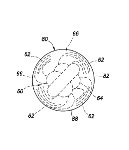
Referring additionally now to FIG. 12, a cross-sectional
view of another example of the device 60 is representatively
illustrated. The device 60 may be used in any of the systems
and methods described herein, or may be used in other systems
and methods.
In this example, the body of the device 60 is made up of
filaments or fibers 62 formed in the shape of a ball or
sphere. Of course, other shapes may be used, if desired.
CA 2992763 2018-01-23
- 28 -
The filaments or fibers 62 may make up all, or
substantially all, of the device 60. The fibers 62 may be
randomly oriented, or they may be arranged in various
orientations as desired.
In the FIG. 12 example, the fibers 62 are retained by the
dissolvable, degradable or dispersible material 82. In
addition, a frangible coating may be provided on the device
60, for example, in order to delay dissolving of the material
82 until the device has been deployed into a well (as in the
example of FIG. 10).
The device 60 of FIG. 12 can be used in a diversion
fracturing operation (in which perforations receiving the most
fluid are plugged to divert fluid flow to other perforations),
in a re-completion operation (e.g., as in the FIGS. 2A-D
example), or in a multiple zone perforate and fracture
operation (e.g., as in the FIGS. 3A-D example).
One advantage of the FIG. 12 device 60 is that it is
capable of sealing on irregularly shaped openings,
perforations, leak paths or other passageways. The device 60
can also tend to "stick" or adhere to an opening, for example,
due to engagement between the fibers 62 and structure
surrounding (and in) the opening. In addition, there is an
ability to selectively seal openings.
The fibers 62 could, in some examples, comprise wool
fibers. The device 60 may be reinforced (e.g., using the
material 82 or another material) or may be made entirely of
fibrous material with a substantial portion of the fibers 62
randomly oriented.
CA 2992763 2018-01-23
- 29 -
The fibers 62 could, in some examples, comprise metal
wool, or crumpled and/or compressed wire. Wool may be retained
with wax or other material (such as the material 82) to form a
ball, sphere, cylinder or other shape.
In the FIG. 12 example, the material 82 can comprise a
wax (or eutectic metal or other material) that melts at a
selected predetermined temperature. A wax device 60 may be
reinforced with fibers 62, so that the fibers and the wax
(material 82) act together to block a perforation or other
passageway.
The selected melting point can be slightly below a static
wellbore temperature. The wellbore temperature during
fracturing is typically depressed due to relatively low
temperature fluids entering wellbore. After fracturing,
wellbore temperature will typically increase, thereby melting
the wax and releasing the reinforcement fibers 62.
This type of device 60 in the shape of a ball or other
shapes may be used to operate downhole tools in a similar
fashion. In FIG. 14, a well tool 110 is depicted with a
passageway 112 extending longitudinally through the well tool.
The well tool 110 could, for example, be connected in the
casing 16 of FIG. 1, or it could be connected in another
tubular string (such as a production tubing string, the
tubular string 12, etc.).
The device 60 is depicted in FIG. 14 as being sealingly
engaged with a seat 114 formed in a sliding sleeve 116 of the
well tool 110. When the device 60 is so engaged in the well
tool 110 (for example, after the well tool is deployed into a
well and appropriately positioned), a pressure differential
CA 2992763 2018-01-23
- 30 -
may be produced across the device and the sliding sleeve 116,
in order to shear frangible members 118 and displace the
sleeve downward (as viewed in FIG. 14), thereby allowing flow
between the passageway 112 and an exterior of the well tool
110 via openings 120 formed through an outer housing 122.
The material 82 of the device 60 can then dissolve,
disperse or otherwise degrade to thereby permit flow through
the passageway 112. Of course, other types of well tools (such
as, packer setting tools, frac plugs, testing tools, etc.) may
be operated or actuated using the device 60 in keeping with
the scope of this disclosure.
A drag coefficient of the device 60 in any of the
examples described herein may be modified appropriately to
produce a desired result. For example, in a diversion
fracturing operation, it is typically desirable to block
perforations in a certain location in a wellbore. The location
is usually at the perforations taking the most fluid.
Natural fractures in an earth formation penetrated by the
wellbore make it so that certain perforations receive a larger
portion of fracturing fluids. For these situations and others,
the device 60 shape, size, density and other characteristics
can be selected, so that the device tends to be conveyed by
flow to a certain corresponding section of the wellbore.
For example, devices 60 with a larger coefficient of drag
(Cd) may tend to seat more toward a toe of a generally
horizontal or lateral wellbore. Devices 60 with a smaller Cd
may tend to seat more toward a heel of the wellbore. For
example, if the wellbore 14 depicted in FIG. 2B is horizontal
or highly deviated, the heel would be at an upper end of the
CA 2992763 2018-01-23
- 31 -
illustrated wellbore, and the toe would be at the lower end of
the illustrated wellbore (e.g., the direction of the fluid
flow 44 is from the heel to the toe).
Smaller devices 60 with long fibers 62 floating freely
(see the example of FIG. 13) may have a strong tendency to
seat at or near the heel. A diameter of the device 60 and the
free fiber 62 length can be appropriately selected, so that
the device is more suited to stopping and sealingly engaging
perforations anywhere along the length of the wellbore.
Acid treating operations can benefit from use of the
device 60 examples described herein. Pumping friction causes
hydraulic pressure at the heel to be considerably higher than
at the toe. This means that the fluid volume pumped into a
formation at the heel will be considerably higher than at the
toe. Turbulent fluid flow increases this effect. Gelling
additives might reduce an onset of turbulence and decrease the
magnitude of the pressure drop along the length of the
wellbore.
Higher initial pressure at the heel allows zones to be
acidized and then plugged starting at the heel, and then
progressively down along the wellbore. This mitigates waste of
acid from attempting to acidize all of the zones at the same
time.
The free fibers 62 of the FIGS. 4-6B & 13 examples
greatly increase the ability of the device 60 to engage the
first open perforation (or other leak path) it encounters.
Thus, the devices 60 with low Cd and long fibers 62 can be
used to plug from upper perforations to lower perforations,
while turbulent acid with high frictional pressure drop is
,
CA 2992763 2018-01-23
- 32 -
used so that the acid treats the unplugged perforations
nearest the top of the wellbore with acid first.
In examples of the device 60 where a wax material (such
as the material 82) is used, the fibers 62 (including the body
64, lines 66, knots, etc.) may be treated with a treatment
fluid that repels wax (e.g., during a molding process). This
may be useful for releasing the wax from the fibrous material
after fracturing or otherwise compromising the retainer 80
and/or a frangible coating thereon.
Suitable release agents are water-wetting surfactants
(e.g., alkyl ether sulfates, high hydrophilic-lipophilic
balance (HLB) nonionic surfactants, betaines,
alkyarylsulfonates, alkyldiphenyl ether sulfonates, alkyl
sulfates). The release fluid may also comprise a binder to
maintain the knot or body 64 in a shape suitable for molding.
One example of a binder is a polyvinyl acetate emulsion.
Broken-up or fractured devices 60 can have lower Cd.
Broken-up or fractured devices 60 can have smaller cross-
sections and can pass through the annulus 30 between tubing 20
and casing 16 more readily.
The restriction 98 (see FIG. 10) may be connected in any
line or pipe that the devices 60 are pumped through, in order
to cause the devices to fracture as they pass through the
restriction. This may be used to break up and separate devices
60 into wax and non-wax parts. The restriction 98 may also be
used for rupturing a frangible coating covering a soluble wax
material 82 to allow water or other well fluids to dissolve
the wax.
CA 2992763 2018-01-23
- 33 -
Fibers 62 may extend outwardly from the device 60,
whether or not the body 64 or other main structure of the
device also comprises fibers. For example, a ball (or other
shape) made of any material could have fibers 62 attached to
and extending outwardly therefrom. Such a device 60 will be
better able to find and cling to openings, holes, perforations
or other leak paths near the heel of the wellbore, as compared
to the ball (or other shape) without the fibers 62.
For any of the device 60 examples described herein, the
fibers 62 may not dissolve, disperse or otherwise degrade in
the well. In such situations, the devices 60 (or at least the
fibers 62) may be removed from the well by swabbing, scraping,
circulating, milling or other mechanical methods.
In situations where it is desired for the fibers 62 to
dissolve, disperse or otherwise degrade in the well, nylon is
a suitable acid soluble material for the fibers. Nylon 6 and
nylon 66 are acid soluble and suitable for use in the device
60. At relatively low well temperatures, nylon 6 may be
preferred over nylon 66, because nylon 6 dissolves faster or
more readily.
Self-degrading fiber devices 60 can be prepared from
poly-lactic acid (PLA), poly-glycolic acid (PGA), or a
combination of PLA and PGA fibers 62. Such fibers 62 may be
used in any of the device 60 examples described herein.
Fibers 62 can be continuous monofilament or
multifilament, or chopped fiber. Chopped fibers 62 can be
carded and twisted into yarn that can be used to prepare
fibrous flow conveyed devices 60.
CA 2992763 2018-01-23
- 34 -
The PLA and/or PGA fibers 62 may be coated with a
protective material, such as calcium stearate, to slow its
reaction with water and thereby delay degradation of the
device 60. Different combinations of PLA and PGA materials may
be used to achieve corresponding different degradation times
or other characteristics.
PLA resin can be spun into fiber of 1-15 denier, for
example. Smaller diameter fibers 62 will degrade faster. Fiber
denier of less than 5 may be most desirable. PLA resin is
commercially available with a range of melting points (e.g.,
140 to 365 F). Fibers 62 spun from lower melting point PLA
resin can degrade faster.
PLA bi-component fiber has a core of high-melting point
PLA resin and a sheath of low-melting point PLA resin (e.g.,
140 F melting point sheath on a 265 F melting point core).
The low-melting point resin can hydrolyze more rapidly and
generate acid that will accelerate degradation of the high-
melting point core. This may enable the preparation of a
fibrous device 60 that will have higher strength in a wellbore
environment, yet still degrade in a reasonable time. In
various examples, a melting point of the resin can decrease in
a radially outward direction in the fiber.
It may now be fully appreciated that the above disclosure
provides significant advancements to the art of controlling
flow in subterranean wells. In some examples described above,
the device 60 may be used to block flow through openings in a
well, with the device being uniquely configured so that its
conveyance with the flow is enhanced and/or its sealing
engagement with an opening is enhanced. A deployment apparatus
CA 2992763 2018-01-23
- 35 -
100 can be used to deploy the devices 60 into the well, so
that a desired spacing between the devices is achieved.
In one aspect, a fibrous plugging device 60 for use in a
subterranean well is provided to the art by the above
disclosure. In one example, the device 60 can comprise a body
64 including fibers 62 and a retainer material 82. The
retainer material 82 retains a shape (e.g., cylindrical,
spherical, cubic, etc.) of the body 64.
The fibers 62 may comprise a material selected from the
group consisting of metal wool, wire, nylon 6 and nylon 66.
The fibers 62 may comprise a core and a sheath overlying
the core. A poly-lactic acid resin in the sheath can have a
lower melting point than a poly-lactic acid resin in the core.
The melting point of the poly-lactic acid resin in each of the
fibers 62 decreases in an outward direction.
The fibers 62 may be included in a yarn. The fibers 62
may comprise a material selected from the group consisting of
poly-lactic acid and poly-glycolic acid. The fibers 62 may be
in a form selected from the group consisting of a) a yarn, b)
monofilament, c) multifilament and d) fabric.
The fibers 62 may be treated with a release agent that
repels the retainer material 82. The release agent may
comprise a water-wetting surfactant. The water-wetting
surfactant may be selected from the group consisting of alkyl
ether sulfate, relatively high hydrophilic-lipophilic balance
nonionic surfactant, betaine, alkylarylsulfonate, alkyl-
diphenyl ether sulfonate and alkyl sulfate.
The fibers 62 may extend outwardly from the body 64.
CA 2992763 2018-01-23
- 36 -
A system 10 for use with a well is also provided to the
art by the above disclosure. In one example, the system 10 can
comprise a fibrous plugging device 60 conveyed by fluid flow
74 in the well. The fibrous plugging device 60 includes a body
64 comprising multiple fibers 62. The fibrous plugging device
60 engages an opening 68 in the well, and thereby seals off
the opening.
The opening 68 may be formed in a well tool 110. The
opening 68 may be circumscribed by a seat 114 that is
sealingly engaged by the fibrous plugging device 60. The well
tool 110 may comprise a valve.
A method for use with a subterranean well is also
described above. In one example, the method can comprise
flowing a fluid 74 through the well, thereby conveying at
least one fibrous plugging device 60 including a body 64
comprising multiple fibers 62; and the fibrous plugging device
60 sealingly engaging at least one opening 68 in the well,
thereby substantially preventing flow through the opening.
Multiple openings 68 may be distributed between a heel
and a toe of a wellbore 14. Multiple fibrous plugging devices
60 may sealingly engaging the openings 68 progressively from
the heel to the toe of the wellbore 14.
The multiple fibrous plugging devices 60 may have
different drag coefficients. The bodies 64 of the fibrous
plugging devices 60 may have different sizes. The fibers 62 of
the fibrous plugging devices 60 may extend different lengths
outwardly from the bodies 64 of the fibrous plugging devices.
CA 2992763 2018-01-23
- 37 -
The fibrous plugging device 60 may degrade in the well.
The method may include mechanically removing the fibrous
plugging device 60 from the opening 68.
Although various examples have been described above, with
each example having certain features, it should be understood
that it is not necessary for a particular feature of one
example to be used exclusively with that example. Instead, any
of the features described above and/or depicted in the
drawings can be combined with any of the examples, in addition
to or in substitution for any of the other features of those
examples. One example's features are not mutually exclusive to
another example's features. Instead, the scope of this
disclosure encompasses any combination of any of the features.
Although each example described above includes a certain
combination of features, it should be understood that it is
not necessary for all features of an example to be used.
Instead, any of the features described above can be used,
without any other particular feature or features also being
used.
It should be understood that the various embodiments
described herein may be utilized in various orientations, such
as inclined, inverted, horizontal, vertical, etc., and in
various configurations, without departing from the principles
of this disclosure. The embodiments are described merely as
examples of useful applications of the principles of the
disclosure, which is not limited to any specific details of
these embodiments.
In the above description of the representative examples,
directional terms (such as "above," "below," "upper," "lower,"
CA 2992763 2018-01-23
- 38 -
etc.) are used for convenience in referring to the
accompanying drawings. However, it should be clearly
understood that the scope of this disclosure is not limited to
any particular directions described herein.
The terms "including," "includes," "comprising,"
"comprises," and similar terms are used in a non-limiting
sense in this specification. For example, if a system, method,
apparatus, device, etc., is described as "including" a certain
feature or element, the system, method, apparatus, device,
etc., can include that feature or element, and can also
include other features or elements. Similarly, the term
"comprises" is considered to mean "comprises, but is not
limited to."
Of course, a person skilled in the art would, upon a
careful consideration of the above description of
representative embodiments of the disclosure, readily
appreciate that many modifications, additions, substitutions,
deletions, and other changes may be made to the specific
embodiments, and such changes are contemplated by the
principles of this disclosure. For example, structures
disclosed as being separately formed can, in other examples,
be integrally formed and vice versa. Accordingly, the
foregoing detailed description is to be clearly understood as
being given by way of illustration and example only, the
spirit and scope of the invention being limited solely by the
appended claims and their equivalents.
CA 2992763 2018-01-23