Note: Descriptions are shown in the official language in which they were submitted.
CA 02992977 2018-01-18
WO 2017/014750 PCT/US2015/041247
SHAPED ELASTOMERIC INFUSION PUMP
FIELD OF THE INVENTION
The present invention relates generally to a liquid dispensing apparatus for
delivering
intravenous drugs, and more particularly to a shaped elastomeric infusion pump
that increases
patient comfort.
BACKGROUND
it is often necessary to intravenously supply patients with pharmaceutically
active liquids at a
controlled rate over a long period of time. It is desirable that this be
accomplished while the patient is
in an ambulatory state. A few devices have been developed in the past for
accomplishing this
purpose.
The prior art devices typically include an inflatable elastomeric bladder
forming a liquid
container and have a flow control valve or device and tubing for supply of the
liquid to the patient.
The walls of the bladder are forced to expand when filled with the liquid, and
provide the pressure for
expelling the liquid. These prior art devices are typically filled by hand by
means of a syringe which
often require an inordinate amount of force.
Another drawback to the prior art devices is that the conventional inflatable
elastomeric
bladder provides pressures and flow rates that can vary widely with the volume
of liquid therein.
Therefore, they do not have a reasonably stable pressure and flow rate over
the infusion period. In
addition, such conventional bladders frequently have difficulty dispensing
substantially all of the liquid
by the end of the infusion period. It is undesirable to have liquid remaining
in the bladder.
Various materials are used for constructing conventional inflatable
elastomeric bladders. For
example, natural rubber is frequently used. Some construction requires several
layers of material,
The use of silicone in tube form to function as a pressurized liquid reservoir
for infusion purposes is
described in, for example, U.S. Patent No. 4,909,790 which discloses an
infusion device that uses
tubular bladders mounted on mandrel supports with downstream restrictors to
deliver uniform flow
rates. Another example may be found in U.S. Patent No. 7,704,230 which
describes a pressurized
fluid reservoir made from a silicone tube for an infusion system. Such
references point to numerous
possible combinations of silicones, structural dimensions, filling pressures,
operating pressures, and
fill volumes. However, the performance provided by the silicone tube disclosed
in US. Patent No.
7,704,230 has been found to be unacceptable for use at least because of the
variability in flow rate
and the pressure during the infusion period and the difficulty dispensing
substantially all of the liquid
by the end of the infusion period.
1
CA 02992977 2018-01-18
WO 2017/014750 PCT/US2015/041247
In addition, many infusion pumps include hard cases (e.g, constructed of
polycarbonate or
similar) with an elastomeric bladder (e,g. constructed of latex, silicone, or
similar) inside, which can
be uncomfortable for the patient to wear, particularly while sleeping.
Alternatively; additional infusion
pumps may include soft cases (e.g, constructed of polyvinyl chloride (PVC) or
similar) with an
elastomeric bladder inside. Such infusion pumps expand spherically and can
also be uncomfortable
for the patient. Thus, the shape of the elastomeric bladder can be difficult
to modify or control when
the bladder is filled with a liquid.
Thus, the present disclosure is directed to a shaped elastomeric infusion pump
that
addresses the aforementioned issues.
SUMMARY OF THE INVENTION
Objects and advantages of the invention will be set forth in part in the
following description,
or may be obvious from the description, or may be learned through practice of
the invention.
In one aspect, the present invention is directed to a portable apparatus for
dispensing a liquid
under pressure at a substantially constant flow rate over a period of time.
The apparatus includes an
inflatable, internal bladder constructed of a compliant, elastomeric material
and an external housing
surrounding the internal bladder. Further, the external housing is constructed
of a non-compliant,
elastomeric material. Thus, during operation, the external housing shapes the
internal bladder as the
internal bladder is being filled with a treatment fluid and collapses as the
treatment fluid is emptied
from the internal bladder.
In one embodiment, the internal bladder may include a support member and an
elastic
sleeve mounted to and surrounding the support member. Further, the support
member may include
a first end and an opposing second end. In further embodiments, at least one
of the first or second
ends may include a fill port configured for fluid communication with a fluid
delivery device while the
other end may include an exit port configured for fluid communication with a
patient. More
specifically, in one embodiment, the first end may include the fill port and
the second end may
include the exit port e.g. that may be connected to a catheter. Thus, in
certain embodiments, the
support member of the internal bladder may include a central bore defining a
fluid passageway that
extends from the first end to the second end.
In additional embodiments, the exit port may include a flow restrictor
configured to provide a
substantially constant flow rate over a predetermined period of time. For
example, in certain
embodiments, the flow rate may range from about 0.1 milliliters per hour
(mL/hr) to about 250 mL/hr.
2
CA 02992977 2018-01-18
WO 2017/014750
PCT/US2015/041247
In further embodiments, the flow range may be controlled to a range below 0.1
mL/hr or above 250
mL/hr.
In specific embodiments, the compliant, elastomeric material of the internal
bladder may
include silicone, latex, rubber, or similar. In particular embodiments, the
non-compliant, elastomeric
material of the external housing may include at least one of nylon, Kevlar,
polyurethane, polyethylene
terephthalate (PET), or other thermoplastic elastomers.
In addition, the external housing may have a predetermined three-dimensional
shape when
filled to capacity, e.g. with a treatment fluid. More specifically, the three-
dimensional shape may
include a plurality of side walls. Further, the side walls may be formed from
an integral piece of
material having a certain thickness. Moreover, in particular embodiments, the
thickness may range
from about 0.01 millimeter (mm) to about 0.15 millimeters. More specifically,
in certain embodiments,
the side wall thickness may range from about 0.04 mm to about 0.12 mm.
In additional embodiments, the three-dimensional shape of the external housing
may be a
generally rectangular shape. Thus, in certain embodiments, the external
housing may be
constructed of a single piece, thin-walled, shaped bag without elasticity. In
further embodiments, the
elastic sleeve of the internal bladder may include a shape that corresponds to
the three-dimensional
shape of the external housing when filled to full capacity. As such, as the
apparatus is filled with a
liquid, the external housing shapes the internal bladder. In addition, the
external housing collapses
as the liquid is emptied from the internal bladder, thereby providing
increased comfort to a patient.
In yet another aspect, the present disclosure is directed to a method for
manufacturing a
portable apparatus for dispensing a liquid under pressure at a substantially
constant flow rate over a
period of time. The method includes forming an inflatable, internal bladder
from a compliant,
elastomeric material. Another step includes forming an external housing from a
non-compliant,
elastomeric material. The method also includes placing the internal bladder
within the external
housing. Thus, during operation, the external housing shapes the internal
bladder as the internal
bladder is being filled with a treatment fluid and collapses as the treatment
fluid is emptied from the
internal bladder. It should also be understood that the portable apparatus may
be further configured
to include any of the additional features as described herein.
In one embodiment, the step of forming the internal bladder may further
include forming a
support member and an elastic sleeve and placing the elastic sleeve around the
support member.
Further, the support member has a first end and an opposing second end. Thus,
at least one of the
first or second ends includes a fill port configured for fluid communication
with a fluid delivery device
and the other end includes an exit port configured for fluid communication
with a patient. For
3
CA 02992977 2018-01-18
WO 2017/014750 PCT/US2015/041247
example, in certain embodiments, the first end may include the fill port and
the second end may
include the exit port. In another embodiment, the step of forming the internal
bladder may also
include forming a central bore within the support member so as to define a
fluid passageway
extending from the first end to the second end.
In additional embodiments, the method may also include forming the external
housing so as
to have a three-dimensional shape when filled to capacity with a treatment
fluid. Further, the three-
dimensional shape may include a plurality of side walls formed from an
integral piece of material.
The method may also include forming the internal bladder so as to have a shape
corresponding to
the three-dimensional shape of the external housing. Thus, the shape of the
internal bladder may
include a fluid passageway extending from the first end to the second end. In
addition, the three-
dimensional shape of the external housing may include a generally rectangular
shape.
These and other features, aspects and advantages of the present invention will
become
better understood with reference to the following description and appended
claims. The
accompanying drawings, which are incorporated in and constitute a part of this
specification,
illustrate embodiments of the invention and, together with the description,
serve to explain the
principles of the invention.
BRIEF DESCRIPTION OF THE DRAWINGS
A full and enabling disclosure of the present invention, including the best
mode thereof,
directed to one of ordinary skill in the art, is set forth in the
specification, which makes reference to
the appended figures, in which:
FIG. 1 illustrates a perspective view of one embodiment of a portable
apparatus for
dispensing a treatment fluid according to the present disclosure, particularly
illustrating the external
housing of the portable apparatus inflated to full capacity;
FIG. 2 illustrates an elevation view of one embodiment of a portable apparatus
for
dispensing a treatment fluid according to the present disclosure, particularly
illustrating the external
housing of the portable apparatus inflated to full capacity;
FIG. 3 illustrates an elevation view of one embodiment of a portable apparatus
for
dispensing a treatment fluid according to the present disclosure, particularly
illustrating the portable
apparatus deflated;
FIG. 4 illustrates an elevation view of one embodiment of a portable apparatus
for
dispensing a treatment fluid according to the present disclosure, particularly
illustrating the internal
bladder of the portable apparatus inflated to full capacity;
4
CA 02992977 2018-01-18
WO 2017/014750 PCT/US2015/041247
FIG. 5 illustrates an end view of the portable apparatus of FIG. 1;
FIG. 6 illustrates a cross-sectional view of the portable apparatus of FIG. 1
along line 6-6;
FIG. 7 illustrates an opposing end view of the portable apparatus of FIG. 1;
FIG. 8 illustrates a detailed, partial view of the portable apparatus of FIG.
4, particularly
illustrating the exit port of the internal bladder having a flow restrictor;
and
FIG. 9 illustrates a flow diagram of one embodiment of a method for
manufacturing a
portable apparatus for dispensing a liquid under pressure at a substantially
constant flow rate over a
period of time according to the present disclosure.
DETAILED DESCRIPTION OF THE INVENTION
Reference will now be made in detail to one or more embodiments of the
invention,
examples of the invention, examples of which are illustrated in the drawings.
Each example and
embodiment is provided by way of explanation of the invention, and is not
meant as a limitation of the
invention. For example, features illustrated or described as part of one
embodiment may be used
with another embodiment to yield still a further embodiment. It is intended
that the invention include
these and other modifications and variations as coming within the scope and
spirit of the invention.
Generally, the present disclosure is directed to a portable apparatus, e.g. an
infusion pump,
for dispensing a liquid under pressure at a substantially constant flow rate
over a period of time. The
apparatus includes an inflatable, internal bladder constructed of a compliant,
elastomeric material
and an external housing surrounding the internal bladder. Further, the
external housing is
constructed of a non-compliant, elastomeric material. Thus, during operation,
the external housing
shapes the internal bladder as the bladder is being filled with a treatment
fluid by forcing the internal
bladder to fill up and conform to the shape of the external housing. In
addition, the external housing
is capable of collapsing as the treatment fluid is emptied from the internal
bladder, thereby improving
patient comfort.
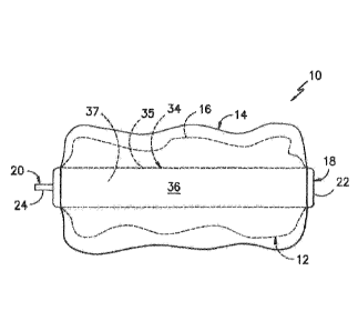
Referring now to the drawings, FIGS. 1-8 illustrate various views of a
portable apparatus 10,
e.g. an infusion pump, for dispensing a treatment fluid according to the
present disclosure. As
shown, the portable apparatus 10 includes inflatable, internal bladder 12
housed within an external
housing 14. More specifically, as shown in FIGS. 3 and 4, the internal bladder
12 may include body
16 having an elongated support member 34 and an elastic sleeve 35 mounted
around the support
member 34. For example, as shown, the support member 34 may be an elongated,
generally
cylindrical mandrel within the housing 14 and may have opposite ends (e.g.
first end 18 and second
end 20) exposed to the exterior of the housing 14. In addition, the elastic
sleeve 35 may be sealingly
5
CA 02992977 2018-01-18
WO 2017/014750 PCT/US2015/041247
clamped at opposite ends thereof around the ends 18, 20 of the support member
34. Further, as
shown, the support member 34 may include a central bore 36 that defines a
fluid passageway 37
extending from the first end 18 to the second end 20. In additional
embodiments, at least one of the
first or second ends 18, 20 may include a fill port 22 configured for fluid
communication with a fluid
delivery device (not shown). Thus, the other or opposite end 18, 20 may
include an exit port 24
configured for fluid communication with a patient. For example, as shown
generally in the figures,
the first end 18 includes the fill port 22, whereas the second end 20 includes
the exit port 24. It
should also be understood that the fill port 22 and the exit port 24 may be
located at any suitable
location on the apparatus 10, including for example, the same side of the
apparatus 10 rather than
on opposite sides as shown. In additional embodiments, as shown in FIG. 8, the
exit port 24 may
also include a flow restrictor 30 configured to provide a substantially
constant flow rate over a period
of time. For example, in certain embodiments, the flow rate may range from
about 0.1 milliliters per
hour (mL/hr) to about 250 mL/hr. In specific embodiments, the flow range may
be controlled to a
range below 0.1 mL/hr or above 250 mL/hr.
Referring now to FIGS. 1-2 and 4-7, the external housing 14 may include a
three-
dimensional shape when filled to capacity with the treatment fluid. It should
be understood that the
three-dimensional shape of the external housing 14 may be any suitable shape
such that the
portable apparatus 10 is comfortable when being worn by a patient. For
example, as shown in the
depicted embodiments, the three-dimensional shape of the external housing 14
may be a generally
rectangular shape. Thus, in such embodiments, the rectangular housing 14 can
be designed with a
relatively thin dimensions (e.g. width) such that the apparatus 10 can be
easily placed flat against a
patient, e.g. a patient's abdomen. Accordingly, the shape of the external
housing 14 is configured to
maximize comfort while being worn by a patient, e.g. while sleeping.
In addition, as shown in FIG. 6, the three-dimensional rectangular shape may
include a
plurality of side walls 38. In certain embodiments, the side walls 38 of the
external housing 14 may
be formed from an integral piece of material having a certain thickness 40.
For example, in particular
embodiments, the thickness 40 of the side walls 38 may range from about 0.01
millimeter (mm) to
about 0.15 millimeters. More specifically, in certain embodiments, the side
wall thickness 40 may
range from about 0.04 mm to about 0.12 mm. Thus, in certain embodiments, the
external housing 14
may be a single piece, thin-walled, shaped bag without elasticity. In
addition, as shown in FIGS. 5
and 7, one or more of the side walls 38 may include one or more openings (e.g.
first and second
openings 26, 28) that are configured to receive the fill port 22 and/or the
exit port 24 of the internal
bladder 12. Thus, the ports 22,24 are easily accessible from outside of the
housing 14. In further
6
CA 02992977 2018-01-18
WO 2017/014750 PCT/US2015/041247
embodiments, the internal bladder 12 may include a generally rectangular body
(when at full
capacity) that corresponds to the generally rectangular shape of the external
housing 14.
In addition, the internal bladder 12 or balloon may be constructed of a
compliant, elastomeric
material. For example, in specific embodiments, the compliant internal bladder
12 may be
constructed of silicon, latex, or similar. Further, the term "compliant" when
used to describe a
material as described herein is generally understood to encompass, e.g. low-
pressure bladders or
balloons having a shape which can expand several times its original size
during use. Thus,
compliant balloons typically cannot be inflated to precise dimensions or
retain well defined shapes
and/or high pressures.
In contrast, the external housing 14 may be constructed of a non-compliant,
elastomeric
material. Thus, the non-compliant external housing 14 can be constructed of a
desired shape such
that the housing 14 can shape the compliant internal bladder 12. For example,
in particular
embodiments, the non-compliant, elastomeric material of the external housing
14 may include nylon,
Kevlar, polyurethane, polyethylene terephthalate (PET), or other thermoplastic
elastomers. As used
herein, a "non-compliant" balloon or housing is generally understood to
encompass a housing that
can be molded to its inflated geometry from non-compliant or low-compliant
materials such that the
housing retains its designed size and shape even under high pressure. Thus,
the non-compliant
external housing 14 is generally thin-walled and exhibits high tensile
strength with relatively low
elongation.
By surrounding the compliant internal bladder 12 with the non-compliant
external housing 14,
the external housing 14 is configured to shape the internal bladder 12 as the
bladder 12 is being filled
with a treatment fluid. In addition, the external housing 14 is configured to
collapse as the treatment
fluid is emptied from the internal bladder 12. Thus, the non-compliant housing
14 over the compliant
bladder 12 provides an infusion pump that can turn into different shapes which
provides increase
comfort for the patient.
Referring now to FIG. 9, a flow diagram of a method 100 for manufacturing a
portable
apparatus for dispensing a liquid under pressure at a substantially constant
flow rate over a period of
time is illustrated. As shown at 102, the method 100 includes forming an
inflatable, internal bladder
12 from a compliant, elastomeric material. As shown at 104, the method 100
includes forming an
external housing 14 from a non-compliant, elastomeric material. As shown at
106, the method 100
includes placing the internal bladder 12 within the external housing 14. For
example, in one
embodiment, the internal bladder 12 may be flexible such that the bladder 12
can be collapsed and
inserted into one of the first or second openings 26, 28. Thus, during
operation, the external housing
7
CA 02992977 2018-01-18
WO 2017/014750 PCT/US2015/041247
14 is configured to shape the internal bladder 12 as the bladder 12 is being
filled with a treatment
fluid. Further, the external housing 14 is configured to collapse as the
treatment fluid is emptied from
the internal bladder 12.
In further embodiments, the step of forming the internal bladder 12 may
further include
forming a body 16 having a first end 18 and an opposing second end 20, wherein
at least one of the
first or second ends 18, 20 includes a fill port 22 configured for fluid
communication with a fluid
delivery device and the other end includes an exit port 24 configured for
fluid communication with a
patient. For example, in certain embodiments, the first end 18 may include the
fill port 22 and the
second end 20 may include the exit port 24. In another embodiment, the step of
forming the internal
bladder 12 may also include forming a central bore 34 within the body 16 that
defines a fluid
passageway 36 extending from the first end 18 to the second end 20.
In additional embodiments, the method 100 may also include forming the
external housing
14 so as to have a three-dimensional shape when filled to capacity with a
treatment fluid. Further, as
mentioned, the three-dimensional shape may include a plurality of side walls
38 formed from an
integral piece of material. Thus, the method 100 may also include forming the
internal bladder 12 so
as to have a shape corresponding to the three-dimensional shape of the
external housing. In
addition, the shape of the internal bladder 12 may include a fluid passageway
36 extending from the
first end 18 to the second end 20. In addition, the three-dimensional shape of
the external housing
14 may include a generally rectangular shape (as generally shown in the
figures) or any other
suitable shape that maximizes comfort of a patient wearing the apparatus 10.
While the present invention has been described in connection with certain
preferred
embodiments it is to be understood that the subject matter encompassed by way
of the present
invention is not to be limited to those specific embodiments. On the contrary,
it is intended for the
subject matter of the invention to include all alternatives, modifications and
equivalents as can be
included within the spirit and scope of the following claims.
8