Language selection

Search

Patent 2993219 Summary

Third-party information liability

Some of the information on this Web page has been provided by external sources. The Government of Canada is not responsible for the accuracy, reliability or currency of the information supplied by external sources. Users wishing to rely upon this information should consult directly with the source of the information. Content provided by external sources is not subject to official languages, privacy and accessibility requirements.

Claims and Abstract availability

Any discrepancies in the text and image of the Claims and Abstract are due to differing posting times. Text of the Claims and Abstract are posted:

  • At the time the application is open to public inspection;
  • At the time of issue of the patent (grant).
(12) Patent Application: (11) CA 2993219
(54) English Title: CONDUIT SUPPORT LOCK BLOCK
(54) French Title: BLOCK DE VERROU DE SUPPORT DE CONDUIT
Status: Deemed Abandoned and Beyond the Period of Reinstatement - Pending Response to Notice of Disregarded Communication
Bibliographic Data
Abstracts

English Abstract


The invention is an interconnecting device for use with conduit support(s),
block(s), hanger(s)or similar
where support is required for flexible, semi-flexible, ridged conduit, pipe,
or similar including electrical
wiring, plumbing piping such as water, waste, gas, and refrigeration piping;
herein referred to as
conduit. The invention is multi-functional where physical attachment is made
to conduit supports
attaching the conduit supports together. In addition, the invention can be
used as a structural
attachment point for conduit supports, including expansion and contraction
engineering built within.
The invention may have a lighted area provided for visual indication of the
support, conduit, or
components. The invention allows for interconnection of conduit supports to
secure two or more
supports together without alteration to conduits being supported by the
supports.


Claims

Note: Claims are shown in the official language in which they were submitted.

What is claimed:
1. A device used to secure, align and attach together conduit supports where
conduit supports are used
for plumbing such as water, drainage, waste, ventilation, refrigeration and
gas pipe(s) which include
heating and air conditioning such as gas lines in the liquid and vapor states
including ridged or semi
ridged or flexible. Electrical distribution conduits and wire including ridged
or semi ridged or flexible.
2. A nonconductive device that when made of nonconductive material will not
allow for galvanic or
conductive action under normal circumstances.
3. A self supporting device wherein the device does not require to be attached
to another structure
such a floor, roof, truss, beam, or any building structure. The device can be
free floating providing
attachment to conduit supports only, when so desired.
4. A self supporting device wherein the device can be used for direct
placement on the earth or ground
areas.
5. A device that can accommodate and attach two or and up to four conduit
supports in any
configuration; but discrimination is not given to the allowance of only one
device used for other than
attachment means.
6. A device that may be used on a singular support, if so desired.
7. A device to where reflectiveness can be provided by means of solar, stored
energy, or self reflective
material for the purpose of visual identification of the device itself,
conduits, conduit components,
supports or similar.
8. A device that can be used as an installation and service tool by where
means is allowed for tool(s) or
accessories to be stored or held within the device.
9. A device that provides when desired, engineering for attachment to
structures including roof, floor,
ground or areas where attachment makes sense.
10. A device that provides when desired, drainage ports for water, rain,
condensate or other similar.
11. A device that provides means for expansion and or contraction built within
the device and
engineered within the device to be used for such purposes when so needed.
12. A device that can be installed without the need for conduit alteration.
13. A device that when attached to more than one support provides a solid base
between the supports
allowing a clean inspection and testing area without outside interference's
such as grass, rocks, dirt,
debris or similar including those placed on purpose such a roofing rocks.

Description

Note: Descriptions are shown in the official language in which they were submitted.


CONDUIT SUPPORT LOCK BLOCK
SUMMARY
The invention as describe is a device for attaching conduit supports together.
The invention
attaches supports together where supports are used to hold plumbing such as
water, drainage,
waste and ventilation pipe(s); plumbing pipe(s) used in heating and air
conditioning such as gas
lines in the liquid and vapor states including ridged or flexible; electrical
distribution, including
ridged or flexible conduits and wire.
The invention in design is a square shaped apparatus that has four sides
elevated from a solid
base, the sides are given elevation change for an area where engineered holes
can be provided
to allow for conventional screws, bolts or similar to be placed or inserted
into. Once these
screws, bolts or similar are placed at the pre-engineered pilot holes they can
be affixed to a free
standing support to where conduits are being or will be supported. The
invention's outside
surface will have a similar mating surface to the supports which are to be
attached. Whereas the
inner surface of the elevated sides have little significance in shape these
inner surfaces may be
sloped to allow for drainage. The base or bottom of the invention will be
flat. The base in some
designs can have pre-engineered slots to allow for conventional screws, bolts
or similar to be
inserted through allowing for structural attachment. These areas will also be
used for drainage
of condensate, moisture, rain, water or similar. The top area of the base may
also include ribs or
bosses added for strength and an area for stored energy such as solar,
batteries, and a light.
The invention summary will become more apparent with the attached drawings.
CA 2993219 2018-01-29

CONDUIT SUPPORT LOCK BLOCK
DESCRIPITION OF THE DRAWINGS
Figure 1
Figure 1 shows the invention CONDUIT SUPPORT LOCK BLOCK 1, a square like
shape with angular sides 2 moving inwards to the inside lower edge 3 where a
reflective
or lighted area 7 is shown; this now formed lower area 3 with sloped edges 2
could also
be used for tradespersons to temporarily in a known contained place hold
tools, fittings,
components, nuts, bolts or other as required by that person performing
installation,
service or repairs in that location. 6 is shown as an elongated open area to
allow for
physical attachment to structures by means of screws, bolts, threaded rod or
other as
5a. 6 incorporates engineering for expansion and contraction also allowing for
drainage
of condensation or moisture. The outside edge is shown in 4 as a flattened
edge which
will later be shown in the drawings to allow for a total and complete seal and
attachment
face to a conduit support by means of screws, bolts or other shown in 5.
Figure la
Figure 1a shows a conduit support 12 placed and installed to the CONDUIT
SUPPORT
LOCK BLOCK 1 with the two flat edges of the conduit support 12 and flattened
edge 4
of the CONDUIT SUPPORT LOCK BLOCK I. 5 is shown with respect for physical
attachment of the CONDUIT SUPPORT LOCK BLOCK 1 to the conduit support 12 by
means of screws, bolts or other.
Figure 2
Figure 2 is shown as a plan view looking down on the invention 1 CONDUIT
SUPPORT
LOCK BLOCK where representation is given without discrimination to the numbers
of
conduit supports 12 that might be attached up to four. Figure 2 shows the
square shape
with angular sides 2 moving inwards to the inside lower edge 3 where a
reflective or
lighted area 7 is shown. 6 is shown as an elongated open area to allow for
physical
attachment to structures which incorporates engineering for expansion and
contraction
also allowing for drainage of condensation or moisture. 5 is shown with
respect for
physical attachment of the CONDUIT SUPPORT LOCK BLOCK 1 to the conduit support
12 by means of screws, bolts or other through predetermined engineered pilot
holes as
shown in 8.
Figure 3
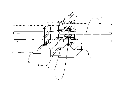
Figure 3 represents the 1 CONDUIT SUPPORT LOCK BLOCK now completely
attached to the conduit supports 12 which are shown attached on opposing sides
of the
1 CONDUIT SUPPORT LOCK BLOCK which shows the transformation of the single
conduit supports 12 aligned, secured and functioning as one conduit support
12. Figure
3 shows the transformation of independent conduit supports 12 to a fully
functioning
CA 2993219 2018-01-29

means of protection from impact or other forces to the conduit 10 and the
conduit
component 9 which is attached to the conduit suports12 by means of conduit
clips 11.
Figure 4
Figure 4 represents the 1 CONDUIT SUPPORT LOCK BLOCK now completely
attached to the conduit supports 12 which are shown attached perpendicular to
each
other which shows the transformation of the single conduit support 12 now
aligned,
secured and functioning as one conduit support 12. Figure 4 shows the
transformation
of independent conduit supports 12 to a fully functioning means of protection
from
impact or forces external to or from the conduits 10 themselves, now providing
protection to the conduit 10 and the conduit component 9 which is attached to
the
conduit supports 12 by means of conduit hanger 11.
Figure 5
Figure 5 represents the 1 CONDUIT SUPPORT LOCK BLOCK now completely
attached to the conduit supports 12 which are shown attached in three
positions which
shows the transformation of the single conduit supports 12 aligned, secured
and
functioning as one conduit support 12. Figure 5 shows the transformation of
independent conduit supports 12 to a fully functioning means of protection
from impact
or forces external to or from the conduits 10 themselves, now providing
protection to the
conduit 10 and the conduit component 9 which is attached to the conduit
supports 12 by
means of conduit clip 11 and threaded rod 11a.
CA 2993219 2018-01-29

Representative Drawing
A single figure which represents the drawing illustrating the invention.
Administrative Status

2024-08-01:As part of the Next Generation Patents (NGP) transition, the Canadian Patents Database (CPD) now contains a more detailed Event History, which replicates the Event Log of our new back-office solution.

Please note that "Inactive:" events refers to events no longer in use in our new back-office solution.

For a clearer understanding of the status of the application/patent presented on this page, the site Disclaimer , as well as the definitions for Patent , Event History , Maintenance Fee  and Payment History  should be consulted.

Event History

Description Date
Application Not Reinstated by Deadline 2021-08-31
Time Limit for Reversal Expired 2021-08-31
Inactive: COVID 19 Update DDT19/20 Reinstatement Period End Date 2021-03-13
Letter Sent 2021-01-29
Deemed Abandoned - Failure to Respond to Maintenance Fee Notice 2020-08-31
Inactive: COVID 19 - Deadline extended 2020-08-19
Inactive: COVID 19 - Deadline extended 2020-08-06
Inactive: COVID 19 - Deadline extended 2020-07-16
Letter Sent 2020-01-29
Common Representative Appointed 2019-10-30
Application Published (Open to Public Inspection) 2019-07-29
Inactive: First IPC assigned 2018-05-02
Inactive: IPC assigned 2018-05-02
Inactive: IPC assigned 2018-05-01
Inactive: Filing certificate - No RFE (bilingual) 2018-02-08
Application Received - Regular National 2018-02-02
Small Entity Declaration Determined Compliant 2018-01-29

Abandonment History

Abandonment Date Reason Reinstatement Date
2020-08-31

Fee History

Fee Type Anniversary Year Due Date Paid Date
Application fee - small 2018-01-29
Owners on Record

Note: Records showing the ownership history in alphabetical order.

Current Owners on Record
SHAWN F. D. PERRY
Past Owners on Record
None
Past Owners that do not appear in the "Owners on Record" listing will appear in other documentation within the application.
Documents

To view selected files, please enter reCAPTCHA code :


To view images, click a link in the Document Description column. To download the documents, select one or more checkboxes in the first column and then click the "Download Selected in PDF format (Zip Archive)" or the "Download Selected as Single PDF" button.

List of published and non-published patent-specific documents on the CPD .

If you have any difficulty accessing content, you can call the Client Service Centre at 1-866-997-1936 or send them an e-mail at CIPO Client Service Centre.


Document
Description 
Date
(yyyy-mm-dd) 
Number of pages   Size of Image (KB) 
Abstract 2018-01-28 1 17
Drawings 2018-01-28 3 133
Description 2018-01-28 3 121
Claims 2018-01-28 1 41
Representative drawing 2019-06-24 1 8
Filing Certificate 2018-02-07 1 217
Commissioner's Notice - Maintenance Fee for a Patent Application Not Paid 2020-03-10 1 534
Courtesy - Abandonment Letter (Maintenance Fee) 2020-09-20 1 552
Commissioner's Notice - Maintenance Fee for a Patent Application Not Paid 2021-03-11 1 538