Sélection de la langue

Search

Sommaire du brevet 2993219 

Énoncé de désistement de responsabilité concernant l'information provenant de tiers

Une partie des informations de ce site Web a été fournie par des sources externes. Le gouvernement du Canada n'assume aucune responsabilité concernant la précision, l'actualité ou la fiabilité des informations fournies par les sources externes. Les utilisateurs qui désirent employer cette information devraient consulter directement la source des informations. Le contenu fourni par les sources externes n'est pas assujetti aux exigences sur les langues officielles, la protection des renseignements personnels et l'accessibilité.

Disponibilité de l'Abrégé et des Revendications

L'apparition de différences dans le texte et l'image des Revendications et de l'Abrégé dépend du moment auquel le document est publié. Les textes des Revendications et de l'Abrégé sont affichés :

  • lorsque la demande peut être examinée par le public;
  • lorsque le brevet est émis (délivrance).
(12) Demande de brevet: (11) CA 2993219
(54) Titre français: BLOCK DE VERROU DE SUPPORT DE CONDUIT
(54) Titre anglais: CONDUIT SUPPORT LOCK BLOCK
Statut: Réputée abandonnée et au-delà du délai pour le rétablissement - en attente de la réponse à l’avis de communication rejetée
Données bibliographiques
Abrégés

Abrégé anglais


The invention is an interconnecting device for use with conduit support(s),
block(s), hanger(s)or similar
where support is required for flexible, semi-flexible, ridged conduit, pipe,
or similar including electrical
wiring, plumbing piping such as water, waste, gas, and refrigeration piping;
herein referred to as
conduit. The invention is multi-functional where physical attachment is made
to conduit supports
attaching the conduit supports together. In addition, the invention can be
used as a structural
attachment point for conduit supports, including expansion and contraction
engineering built within.
The invention may have a lighted area provided for visual indication of the
support, conduit, or
components. The invention allows for interconnection of conduit supports to
secure two or more
supports together without alteration to conduits being supported by the
supports.

Revendications

Note : Les revendications sont présentées dans la langue officielle dans laquelle elles ont été soumises.


What is claimed:
1. A device used to secure, align and attach together conduit supports where
conduit supports are used
for plumbing such as water, drainage, waste, ventilation, refrigeration and
gas pipe(s) which include
heating and air conditioning such as gas lines in the liquid and vapor states
including ridged or semi
ridged or flexible. Electrical distribution conduits and wire including ridged
or semi ridged or flexible.
2. A nonconductive device that when made of nonconductive material will not
allow for galvanic or
conductive action under normal circumstances.
3. A self supporting device wherein the device does not require to be attached
to another structure
such a floor, roof, truss, beam, or any building structure. The device can be
free floating providing
attachment to conduit supports only, when so desired.
4. A self supporting device wherein the device can be used for direct
placement on the earth or ground
areas.
5. A device that can accommodate and attach two or and up to four conduit
supports in any
configuration; but discrimination is not given to the allowance of only one
device used for other than
attachment means.
6. A device that may be used on a singular support, if so desired.
7. A device to where reflectiveness can be provided by means of solar, stored
energy, or self reflective
material for the purpose of visual identification of the device itself,
conduits, conduit components,
supports or similar.
8. A device that can be used as an installation and service tool by where
means is allowed for tool(s) or
accessories to be stored or held within the device.
9. A device that provides when desired, engineering for attachment to
structures including roof, floor,
ground or areas where attachment makes sense.
10. A device that provides when desired, drainage ports for water, rain,
condensate or other similar.
11. A device that provides means for expansion and or contraction built within
the device and
engineered within the device to be used for such purposes when so needed.
12. A device that can be installed without the need for conduit alteration.
13. A device that when attached to more than one support provides a solid base
between the supports
allowing a clean inspection and testing area without outside interference's
such as grass, rocks, dirt,
debris or similar including those placed on purpose such a roofing rocks.

Description

Note : Les descriptions sont présentées dans la langue officielle dans laquelle elles ont été soumises.

CONDUIT SUPPORT LOCK BLOCK
SUMMARY
The invention as describe is a device for attaching conduit supports together.
The invention
attaches supports together where supports are used to hold plumbing such as
water, drainage,
waste and ventilation pipe(s); plumbing pipe(s) used in heating and air
conditioning such as gas
lines in the liquid and vapor states including ridged or flexible; electrical
distribution, including
ridged or flexible conduits and wire.
The invention in design is a square shaped apparatus that has four sides
elevated from a solid
base, the sides are given elevation change for an area where engineered holes
can be provided
to allow for conventional screws, bolts or similar to be placed or inserted
into. Once these
screws, bolts or similar are placed at the pre-engineered pilot holes they can
be affixed to a free
standing support to where conduits are being or will be supported. The
invention's outside
surface will have a similar mating surface to the supports which are to be
attached. Whereas the
inner surface of the elevated sides have little significance in shape these
inner surfaces may be
sloped to allow for drainage. The base or bottom of the invention will be
flat. The base in some
designs can have pre-engineered slots to allow for conventional screws, bolts
or similar to be
inserted through allowing for structural attachment. These areas will also be
used for drainage
of condensate, moisture, rain, water or similar. The top area of the base may
also include ribs or
bosses added for strength and an area for stored energy such as solar,
batteries, and a light.
The invention summary will become more apparent with the attached drawings.
CA 2993219 2018-01-29

CONDUIT SUPPORT LOCK BLOCK
DESCRIPITION OF THE DRAWINGS
Figure 1
Figure 1 shows the invention CONDUIT SUPPORT LOCK BLOCK 1, a square like
shape with angular sides 2 moving inwards to the inside lower edge 3 where a
reflective
or lighted area 7 is shown; this now formed lower area 3 with sloped edges 2
could also
be used for tradespersons to temporarily in a known contained place hold
tools, fittings,
components, nuts, bolts or other as required by that person performing
installation,
service or repairs in that location. 6 is shown as an elongated open area to
allow for
physical attachment to structures by means of screws, bolts, threaded rod or
other as
5a. 6 incorporates engineering for expansion and contraction also allowing for
drainage
of condensation or moisture. The outside edge is shown in 4 as a flattened
edge which
will later be shown in the drawings to allow for a total and complete seal and
attachment
face to a conduit support by means of screws, bolts or other shown in 5.
Figure la
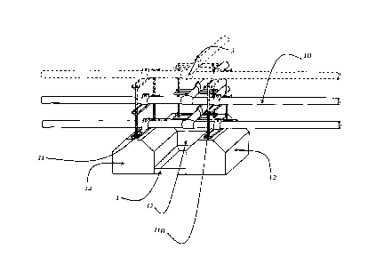
Figure 1a shows a conduit support 12 placed and installed to the CONDUIT
SUPPORT
LOCK BLOCK 1 with the two flat edges of the conduit support 12 and flattened
edge 4
of the CONDUIT SUPPORT LOCK BLOCK I. 5 is shown with respect for physical
attachment of the CONDUIT SUPPORT LOCK BLOCK 1 to the conduit support 12 by
means of screws, bolts or other.
Figure 2
Figure 2 is shown as a plan view looking down on the invention 1 CONDUIT
SUPPORT
LOCK BLOCK where representation is given without discrimination to the numbers
of
conduit supports 12 that might be attached up to four. Figure 2 shows the
square shape
with angular sides 2 moving inwards to the inside lower edge 3 where a
reflective or
lighted area 7 is shown. 6 is shown as an elongated open area to allow for
physical
attachment to structures which incorporates engineering for expansion and
contraction
also allowing for drainage of condensation or moisture. 5 is shown with
respect for
physical attachment of the CONDUIT SUPPORT LOCK BLOCK 1 to the conduit support
12 by means of screws, bolts or other through predetermined engineered pilot
holes as
shown in 8.
Figure 3
Figure 3 represents the 1 CONDUIT SUPPORT LOCK BLOCK now completely
attached to the conduit supports 12 which are shown attached on opposing sides
of the
1 CONDUIT SUPPORT LOCK BLOCK which shows the transformation of the single
conduit supports 12 aligned, secured and functioning as one conduit support
12. Figure
3 shows the transformation of independent conduit supports 12 to a fully
functioning
CA 2993219 2018-01-29

means of protection from impact or other forces to the conduit 10 and the
conduit
component 9 which is attached to the conduit suports12 by means of conduit
clips 11.
Figure 4
Figure 4 represents the 1 CONDUIT SUPPORT LOCK BLOCK now completely
attached to the conduit supports 12 which are shown attached perpendicular to
each
other which shows the transformation of the single conduit support 12 now
aligned,
secured and functioning as one conduit support 12. Figure 4 shows the
transformation
of independent conduit supports 12 to a fully functioning means of protection
from
impact or forces external to or from the conduits 10 themselves, now providing
protection to the conduit 10 and the conduit component 9 which is attached to
the
conduit supports 12 by means of conduit hanger 11.
Figure 5
Figure 5 represents the 1 CONDUIT SUPPORT LOCK BLOCK now completely
attached to the conduit supports 12 which are shown attached in three
positions which
shows the transformation of the single conduit supports 12 aligned, secured
and
functioning as one conduit support 12. Figure 5 shows the transformation of
independent conduit supports 12 to a fully functioning means of protection
from impact
or forces external to or from the conduits 10 themselves, now providing
protection to the
conduit 10 and the conduit component 9 which is attached to the conduit
supports 12 by
means of conduit clip 11 and threaded rod 11a.
CA 2993219 2018-01-29

Dessin représentatif
Une figure unique qui représente un dessin illustrant l'invention.
États administratifs

2024-08-01 : Dans le cadre de la transition vers les Brevets de nouvelle génération (BNG), la base de données sur les brevets canadiens (BDBC) contient désormais un Historique d'événement plus détaillé, qui reproduit le Journal des événements de notre nouvelle solution interne.

Veuillez noter que les événements débutant par « Inactive : » se réfèrent à des événements qui ne sont plus utilisés dans notre nouvelle solution interne.

Pour une meilleure compréhension de l'état de la demande ou brevet qui figure sur cette page, la rubrique Mise en garde , et les descriptions de Brevet , Historique d'événement , Taxes périodiques et Historique des paiements devraient être consultées.

Historique d'événement

Description Date
Demande non rétablie avant l'échéance 2021-08-31
Le délai pour l'annulation est expiré 2021-08-31
Inactive : COVID 19 Mis à jour DDT19/20 fin de période de rétablissement 2021-03-13
Lettre envoyée 2021-01-29
Réputée abandonnée - omission de répondre à un avis sur les taxes pour le maintien en état 2020-08-31
Inactive : COVID 19 - Délai prolongé 2020-08-19
Inactive : COVID 19 - Délai prolongé 2020-08-06
Inactive : COVID 19 - Délai prolongé 2020-07-16
Lettre envoyée 2020-01-29
Représentant commun nommé 2019-10-30
Demande publiée (accessible au public) 2019-07-29
Inactive : CIB en 1re position 2018-05-02
Inactive : CIB attribuée 2018-05-02
Inactive : CIB attribuée 2018-05-01
Inactive : Certificat dépôt - Aucune RE (bilingue) 2018-02-08
Demande reçue - nationale ordinaire 2018-02-02
Déclaration du statut de petite entité jugée conforme 2018-01-29

Historique d'abandonnement

Date d'abandonnement Raison Date de rétablissement
2020-08-31

Historique des taxes

Type de taxes Anniversaire Échéance Date payée
Taxe pour le dépôt - petite 2018-01-29
Titulaires au dossier

Les titulaires actuels et antérieures au dossier sont affichés en ordre alphabétique.

Titulaires actuels au dossier
SHAWN F. D. PERRY
Titulaires antérieures au dossier
S.O.
Les propriétaires antérieurs qui ne figurent pas dans la liste des « Propriétaires au dossier » apparaîtront dans d'autres documents au dossier.
Documents

Pour visionner les fichiers sélectionnés, entrer le code reCAPTCHA :


Pour visualiser une image, cliquer sur un lien dans la colonne description du document. Pour télécharger l'image (les images), cliquer l'une ou plusieurs cases à cocher dans la première colonne et ensuite cliquer sur le bouton "Télécharger sélection en format PDF (archive Zip)" ou le bouton "Télécharger sélection (en un fichier PDF fusionné)".

Liste des documents de brevet publiés et non publiés sur la BDBC .

Si vous avez des difficultés à accéder au contenu, veuillez communiquer avec le Centre de services à la clientèle au 1-866-997-1936, ou envoyer un courriel au Centre de service à la clientèle de l'OPIC.


Description du
Document 
Date
(aaaa-mm-jj) 
Nombre de pages   Taille de l'image (Ko) 
Abrégé 2018-01-28 1 17
Dessins 2018-01-28 3 133
Description 2018-01-28 3 121
Revendications 2018-01-28 1 41
Dessin représentatif 2019-06-24 1 8
Certificat de dépôt 2018-02-07 1 217
Avis du commissaire - non-paiement de la taxe de maintien en état pour une demande de brevet 2020-03-10 1 534
Courtoisie - Lettre d'abandon (taxe de maintien en état) 2020-09-20 1 552
Avis du commissaire - non-paiement de la taxe de maintien en état pour une demande de brevet 2021-03-11 1 538