Note: Descriptions are shown in the official language in which they were submitted.
CA 02993774 2018-01-25
WO 2017/017315 PCT/F12016/050545
- 1 -
Improvements in grinding mills
Field of the Invention
[0001] The invention relates to improvements in grinding mills and in
particular to a
stirring device for a grinding mill, stirring device assembly, mill body,
grinding mill and
method for grinding particulate material. The invention has been developed
primarily for
use in a fine grinding mill for grinding mineral ore particles. However, it
will be
appreciated that the invention is applicable in the grinding of other
particulate material,
such as concrete, cement, recyclable materials (such as glass, ceramics,
electronics and
metals), food, paint pigments, abrasives and pharmaceutical substances.
Background of the Invention
[0001] Grinding mills are typically used in mineral processing to grind
mineral ore
particles into smaller sized particles to facilitate further downstream
processing, such as
separation of the valuable mineral particles from unwanted gangue. One type of
grinding
mill is a fine grinding mill for grinding mineral ore particles in the range
of about 30pm to
4000pm in diameter down to particles of 5 to 40pm in diameter. As fine
grinding mills
consume a large amount of power per tonne of ore processed, they are typically
used on
a concentrate stream comprising mostly of a high-grade mineral ore that has
already
been ground using a ball or SAG type grinding mill that performs coarse
grinding as it is
more economic.
[0002] The fine grinding mill has a stationary mill body or shell arranged
vertically in
the mill and an internal drive shaft. The drive shaft has a plurality of
stirring elements,
such as grinding discs, so that rotation of the drive shaft also rotates the
stirring
elements, which in turn rotates or stirs the mineral ore particles, usually in
the form of a
feed slurry, with a suitable grinding media. The resulting stirring action
causes the
mineral ore particles to be ground into smaller sized particles. However, the
grinding
discs tend to suffer from excessive wear, especially when the grinding mill is
operated at
high speeds through the action of the harder grinding media impacting against
the
grinding discs.
CA 02993774 2018-01-25
WO 2017/017315 PCT/F12016/050545
- 2 -
Summary of the Invention
[0003] A first aspect of the present invention provides a stirring device
for stirring a
particulate material and a grinding media in a grinding mill, comprising one
or more
protective elements that extend outwardly from a body to deflect said
particulate material
and said grinding media from said body.
[0004] Preferably, said one or more protective elements comprise a
deflection
surface, said deflection surface being arranged at an angle to a direction of
rotation of
said body. More preferably, said deflection surface is at an angle in the
range of 10 to
170 , preferably 20 to 160 , preferably 30 to 150 , preferably 40 to 130 ,
preferably
50 to 120 , preferably 60 to 110 , more preferably 70 to 100 , even more
preferably
80 to 95 , and most preferably 85 to 90 . In one embodiment, said deflection
surface is
orthogonal to the direction of rotation of said body.
[0005] Preferably, said one or more protective elements extend at an angle
to a
surface of said body. More preferably, said angle is in the range of 10 to
170 ,
preferably 20 to 160 , preferably 30 to 150 , preferably 40 to 130 ,
preferably 50 to
120 , preferably 60 to 110 , more preferably 70 to 100 , even more
preferably 80 to
95 , and most preferably 85 to 90 . In one embodiment, said one or more
protective
elements extend orthogonally from said surface. In some embodiments, said body
surface is a planar surface. In other embodiments, said body surface is a non-
planar
surface.
[0006] Preferably, said body comprises an outer edge, wherein said one or
more
protective elements extend from said outer edge. More preferably, said one or
more
protective elements extend radially from said outer edge.
[0007] Preferably, said body comprises opposed surfaces and said one or
more
protective elements extend from at least one of said opposed surfaces. More
preferably,
said one of more protective elements extend from each of said opposed
surfaces.
[0008] Preferably, there is a plurality of said protective elements, said
protective
elements being spaced apart around said body. More preferably, said protective
CA 02993774 2018-01-25
WO 2017/017315 PCT/F12016/050545
- 3 -
elements are spaced apart at regular intervals. In one embodiment, said
protective
elements are spaced apart at irregular or uneven intervals. In a further
embodiment,
some of said protective elements are spaced apart at regular intervals on one
portion of
said body and other of said protective elements are spaced apart at irregular
intervals on
another portion of said body.
[0009] Preferably, said body comprises an annular shape. In one embodiment,
said
body comprises an annular disc. More preferably, said opposed surfaces are
planar
surfaces. In one embodiment, said outer edge is an outer circumferential edge
of said
annular disc. In some embodiments, said annular disc has a diameter in the
range of
250mm to 3000mm, preferably 300mm to 2750mm and most preferably 400mm to
2500mm.
[0010] The one or more protective elements can be configured into different
shapes.
Preferably, said one of more protective elements each comprise at least one or
more of a
projection, an elongated body, a block-shaped element, a flange, a tooth, a
planar
element, a vane, a blade, a fin, a plate, a bar, a post, a rod, a channel-
shaped element, a
V-shaped element, a U-shaped element, a depression, a recess, a ramp-like
element
and a wedge-shaped element.
[0011] Preferably, said one or more protective elements are substantially
linear in
shape. Alternatively, one or more protective elements have a non-linear
configuration.
For example, the protective element(s) may be helical, spiral, sinuous or
curved, in whole
or part.
[0012] Where said one or more protective elements comprise said block-
shaped
element, said block-shaped element is preferably connected to said planar body
so that
opposed sides of said block-shaped element extend outwardly from said opposed
surfaces of said planar body. In one embodiment, said block-shaped element
comprises
an outer end that extends radially outwardly from an outer edge of said planar
body. In
some embodiments, said block-shaped element is integrally forms with said
planar body.
In other embodiments, said block-shaped element is U-shaped for mounting to
said
planar body.
CA 02993774 2018-01-25
WO 2017/017315 PCT/F12016/050545
- 4 -
[0013] Preferably, where said one or more protective elements comprise said
planar
element, said planar element is inclined relative to the said planar body. In
one
embodiment, said planar element is inclined towards a direction of rotation of
said stirring
device. In another embodiment, said planar element is inclined away from a
direction of
rotation of said stirring device.
[0014] Preferably, said planar element comprises a vane, blade, planar
tooth or plate.
[0015] Preferably, said one or more protective elements are integrally
formed with
said body.
[0016] A second aspect of the present invention provides the use of the
stirring device
of the first aspect of the invention in a stirring device assembly.
[0017] A third aspect of the present invention provides a stirring device
assembly for
stirring a particulate material and a grinding media in a grinding mill,
comprising a
plurality of stirring devices of the first aspect of the invention mounted to
a drive shaft for
rotating said stirring devices.
[0018] Preferably, said stirring devices are spaced apart along the length
of said drive
shaft.
[0019] Preferably, said drive shaft comprises one or more of protective
elements
extending radially from said drive shaft. More preferably, said protective
elements have
the same features as the preferred features of the one or more protective
elements of the
first aspect of the invention.
[0020] A fourth aspect of the present invention provides the use of the
stirring device
assembly of the third aspect of the invention as a mill impeller in a grinding
mill.
[0021] A fifth aspect of the present invention provides a drive shaft
assembly for
stirring a particulate material and a grinding media in a grinding mill,
comprising a drive
shaft and a plurality of protective elements for deflecting said particulate
material and
said grinding media from said drive shaft.
CA 02993774 2018-01-25
WO 2017/017315 PCT/F12016/050545
- 5 -
[0022] Preferably, said protective elements are spaced apart along the
length of said
drive shaft.
[0023] Preferably, at least two of said protective elements extend from
either side of
said drive shaft. In one embodiment, said protective elements extend radially
outwardly
from said drive shaft. In some embodiments, said protective elements are
arranged
around the circumference of said drive shaft.
[0024] Preferably, said protective elements have the same features as the
preferred
features of the protective elements of the first aspect of the invention,
where applicable.
For example, the protective elements also preferably have a deflection surface
as in the
first aspect of the invention, but which is arranged at angle to the direction
of rotation of
the drive shaft and not a stirring device body. In this case, the preferred
ranges of the
angle are the same, including providing the deflection surface substantially
orthogonal to
the direction of rotation of the drive shaft. Likewise, the protective
elements may also
extend at an angle, but with respect to the direction of rotation of the drive
shaft and not
a stirring device body. In one particularly preferred embodiment, said
protective
elements have a planar or non-curved deflection surface.
[0025] A sixth aspect of the present invention provides the use of the
drive shaft
assembly of the fourth aspect of the invention as a mill impeller in a
grinding mill.
[0026] A seventh aspect of the present invention provides a mill body
comprising the
stirring device assembly of the third aspect of the invention or the drive
shaft assembly of
the fourth aspect of the invention.
[0027] Preferably, said mill body further comprises an inlet for receiving
a particulate
material and an outlet for discharging ground particles.
[0028] Preferably, said mill body comprises one or more shelves extending
from an
inner sidewall, said one or more shelves define one or more chambers
containing said
stirring devices or said protective elements, and openings communicating
between said
chambers.
CA 02993774 2018-01-25
WO 2017/017315 PCT/F12016/050545
- 6 -
[0029] Preferably, said one or more shelves alternate between said one or
more
stirring devices or said protective elements.
[0030] Preferably, said mill body is arranged vertically in said mill.
In some
embodiments, said mill body is arranged at an angle in said mill. In other
embodiments,
said mill body is arranged horizontally in said mill.
[0031] Preferably, said inlet is at the bottom of said mill body and said
inlet is at the
top of said mill body.
[0032] An eighth aspect of the present invention provides a grinding mill
comprising
the mill body of the seventh aspect of the invention.
[0033] Preferably, said grinding mill is a fine grinding mill. More
preferably, said fine
grinding mill has a power consumption of 10 to 70 kilowatt hours per tonne
(kWhr/t). In
one preferred embodiment, said fine grinding mill has a power consumption of
30kWhr/t.
[0034] A ninth aspect of the present invention provides a mill body for
grinding a
particulate material comprising an inlet for receiving said particulate
material, an outlet
for discharging ground particles and a shelf extending from an inner sidewall,
said shelf
comprising one or more protective elements that extend outwardly from said
shelf to
deflect said particulate material and said grinding media said shelf.
[0035] Preferably, said one or more protective elements extend radially
from said
shelf.
[0036] Preferably, said shelf comprises opposed surfaces and said one or
more
protective elements extend from at least one of said opposed surfaces. More
preferably,
said one of more protective elements extend from each of said opposed
surfaces.
[0037] Preferably, said one or more protective elements extend orthogonally
from at
least one of said opposed surfaces. More preferably, said one or more
protective
elements extend orthogonally from each of said opposed surfaces.
CA 02993774 2018-01-25
WO 2017/017315 PCT/F12016/050545
- 7 -
[0038] Preferably, there is a plurality of said protective elements, said
protective
elements being spaced apart around said shelf. In one embodiment, said
protective
elements are spaced apart at regular intervals. In another embodiment, said
protective
elements are spaced apart at uneven or regular intervals.
[0039] Preferably, said one or more protective elements of the sixth aspect
have the
same features as the preferred features of the one or more protective elements
of the
first aspect of the present invention, where applicable.
[0040] Preferably, said shelf is annular in shape. In some embodiments,
said shelf is
angled relative to the inner sidewall. In other embodiments, said shelf is a
static counter
disc.
[0041] A tenth aspect of present invention provides a grinding mill
comprising the mill
body of the ninth aspect of the invention, a drive shaft and a plurality of
stirring elements
mounted to said drive shaft.
[0042] Preferably, the grinding mill of the ninth aspect has the preferred
features of
the eighth aspect of the invention, where applicable.
[0043] An eleventh aspect of the present invention provides a method of
grinding a
particulate material in a grinding mill of the type having a mill body and a
drive shaft for
rotating a plurality of stirring devices within said mill body, said method
comprising:
introducing grinding media into said mill body;
introducing said particulate material through an inlet; and
operating said drive shaft to rotate said stirring devices within said mill
body;
wherein said rotation of said stirring devices induces a rotating flow of said
particulate material within said mill body to grind said particulate material
against said
grinding media to produce smaller sized particles; and
wherein one or more protective elements deflect said particulate material and
said grinding media away from said stirring devices.
CA 02993774 2018-01-25
WO 2017/017315 PCT/F12016/050545
- 8 -
[0044] Preferably, said method comprises creating a zone around said
stirring devices
where said grinding media is captured by said one or more protective elements
and
rotated with said stirring devices.
[0045] Preferably, said method comprises arranging said one or more
protective
elements at an angle to a direction of rotation of said stirring devices.
[0046] Preferably, said one or more protective elements comprise a
deflection
surface, said method comprising arranging said deflection surface at an angle
to a
direction of rotation of said stirring devices.
[0047] Preferably, said angle is in the range of 10 to 170 , preferably 20
to 160 ,
preferably 30 to 150 , preferably 40 to 130 , preferably 50 to 120 ,
preferably 60 to
110 , more preferably 70 to 100 , even more preferably 80 to 95 , and most
preferably
85 to 90 . In one embodiment, said method comprising arranging said
deflection
surface orthogonally to the direction of rotation.
[0048] Preferably, said method comprises locating said one or more
protective
elements adjacent said stirring devices. In some embodiments, said one or more
protective elements extend from said stirring devices. In other embodiments,
said one or
more protective elements extend from a shelf extending from an inner sidewall
of said
mill body.
[0049] A twelfth aspect of the present invention provides a method of
grinding a
particulate material in the grinding mill of the type having a mill body and a
drive shaft
assembly comprising a plurality of protective elements extending from a drive
shaft, said
method comprising:
introducing grinding media into said mill body;
introducing said particulate material through an inlet; and
operating said drive shaft to rotate said drive shaft assembly within said
mill
body;
wherein said rotation of said drive shaft assembly induces a rotating flow of
said particulate material within said mill body to grind said particulate
material against
said grinding media to produce smaller sized mineral particles; and
CA 02993774 2018-01-25
WO 2017/017315 PCT/F12016/050545
- 9 -
wherein said protective elements deflect said particulate material and said
grinding media away from said drive shaft.
[0050] Preferably, said particulate material comprises mineral particles.
More
preferably, said mineral particles have a F80 of 30pm to 4000pm, preferably
35pm to
3000pm, preferably 40pm to 2000pm, preferably 45pm to 1500pm, even more
preferably
50pm to 1000pm, preferably 60pm to 750pm, further preferably 65pm to 500pm,
further
more preferably 70pm to 400pm, even more preferably 75pm to 300pm and most
preferably 80pm to 200pm.
[0051] Preferably, wherein said smaller sized mineral particles have a P80
of 0.1 pm to
1000pm, preferably 0.25pm to 750pm, preferably 0.3pm to 500pm, preferably
0.4pm to
400pm, preferably 0.5pm to 300pm, preferably 0.6pm to 250pm, preferably 0.7pm
to
200pm further preferably 0.75pm to 150pm, further more preferably 0.8pm to
100pm,
even more preferably 0.9pm to 75pm and most preferably 1pm to 50pm.
[0052] Preferably, wherein said particulate material comprises mineral
particles. More
preferably, said mineral particles are mineral ore particles having a density
of at least
2,000 kg/m3. In some embodiments, said mineral ore particles comprises at
least one of
iron. quartz, copper, nickel, zinc, lead, gold, silver, platinum, tungsten,
chromium, silicon
and combinations thereof.
[0053] Preferably, said particulate material comprises at least one of
concrete,
cement, recyclable material, pharmaceutical substances, paint pigment,
abrasives and
food. In some embodiments, said recyclable material comprises at least one of
glass,
ceramics, electronics and metals.
[0054] The methods of the tenth and eleventh aspects of the invention have
the
preferred features of any previous aspect of the invention, where applicable.
In particular,
said protective elements have the preferred features of the first aspect of
the invention,
where applicable.
[0055] Unless the context clearly requires otherwise, throughout the
description and
the claims, the words "comprise", "comprising", and the like are to be
construed in an
CA 02993774 2018-01-25
WO 2017/017315 PCT/F12016/050545
- 10 -
inclusive sense as opposed to an exclusive or exhaustive sense; that is to
say, in the
sense of "including, but not limited to".
[0056] Furthermore, as used herein and unless otherwise specified, the use
of the
ordinal adjectives "first", "second", "third", etc., to describe a common
object, merely
indicate that different instances of like objects are being referred to, and
are not intended
to imply that the objects so described must be in a given sequence, either
temporally,
spatially, in ranking, or in any other manner.
Brief Description of the Drawings
[0057] Preferred embodiments of the invention will now be described, by way
of
example only, with reference to the accompanying drawings in which:
[0058] Figure 1 is a perspective view of a grinding mill having a stirring
device
assembly comprising a plurality of stirring devices according to an embodiment
of the
invention;
[0059] Figure 2 is a front view of the grinding mill of Figure 1;
[0060] Figure 3 is a side view of the grinding mill of Figure 1;
[0061] Figure 4 is a rear view of the mill body used in the grinding mill
of Figure 1;
[0062] Figure 5 is a cross-sectional view of the mill body of Figure 4;
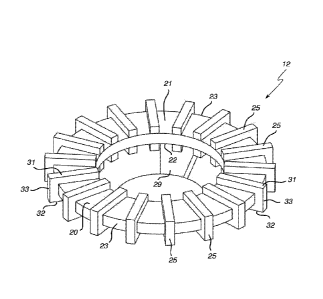
[0063] Figure 6 is a partial cross-sectional perspective view of the mill
body of Figure
4;
[0064] Figure 7 is a partial cross-sectional view of the mill body of
Figure 4 at the
mounting ring indicated by area A in Figure 5;
[0065] Figure 8 is a top view of the mill body of Figure 4;
CA 02993774 2018-01-25
WO 2017/017315 PCT/F12016/050545
- 11 -
[0066] Figure 9 is a perspective view of a stirring device in the stirring
device
assembly used in the mill body of Figure 1;
[0067] Figure 10 is a side view of the stirring device of Figure 9;
[0068] Figure 11 is a cross-sectional view of the stirring device of Figure
9;
[0069] Figures 12A to 12G are partial perspective views of stirring devices
according
to other embodiments of the invention;
[0070] Figures 13A to 13E are partial perspective views of stirring devices
and drive
shaft assemblies according to other embodiments of the invention;
[0071] Figure 14 is a partial cross-sectional view of a mill body according
to another
embodiment of the invention; and
[0072] Figure 15 is a partial cross-sectional view of a mill body according
to another
embodiment of the invention.
Preferred Embodiments of the Invention
[0073] The present invention will now be described with reference to the
following
examples which should be considered in all respects as illustrative and non-
restrictive.
In the Figures, corresponding features within the same embodiment or common to
different embodiments have been given the same reference numerals. Referring
to
Figures 1 to 3, a grinding mill 1 for grinding a slurry having particulate
material comprises
a mill body 2 mounted on a base frame 3 and a drive mechanism 4 mounted on a
drive
frame 5 for rotating the mill body 3 about a longitudinal axis 6.
[0074] In this embodiment, the mill body 2 is arranged vertically in the
grinding mill 1
and has a bottom inlet 7 and a top outlet 8. It will be appreciated that in
other
embodiments, the mill body 2 is arranged to be inclined or at an angle in the
grinding mill
1. In some embodiments, the mill body 2 is arranged to lie horizontally in the
grinding
mill 1. Likewise, in other embodiments, the inlet 7a and outlet 8 can be
placed at
locations of the mill body 2 other than the bottom and top, respectively.
CA 02993774 2018-01-25
WO 2017/017315 PCT/F12016/050545
- 12 -
[0075] A charge of feed slurry comprising mineral ore particles is fed into
the mill body
2 through the bottom inlet 7. Grinding media M is also added into the mill
body 2 initially
through the outlet 8 before the feed slurry is added and grinding mill 1 is in
operation.
Once the grinding mill 1 is in operation, the initial charge of grinding media
M tends to
wear out due to the grinding process. Accordingly, grinding media M is also
progressively added with the feed slurry through the inlet 7 as the grinding
mill 1
operates. The grinding media M typically comprises ceramic or steel beads that
range
from 1mm to 5mm in diameter. The size of the grinding media M may vary in
other
embodiments, depending on requirements. For example, the diameter of the
grinding
media can be 30 or 50 times the diameter of the slurry particles, which can be
measured
by reference to F80 or F100, which is discussed in more detail below. The mill
body 2 is
rotated by the drive mechanism 4 about the axis 6 to rotate or stir the feed
slurry and
grinding media together, causing the feed slurry particles to be crushed or
ground
against between the grinding media. The ground product is then discharged
through the
top outlet 8.
[0076] Referring to Figures 4 to 8, the mill body 2 comprises a mounting
assembly 9
for fitting the mill body to the base frame 3 and operatively aligning the
mill body to the
drive mechanism 4. The mounting assembly 9 comprises a support gusset 9a and a
mounting hinge 9b. The mill body 2 also comprises a stirring device assembly
10
comprising a drive shaft 11 to which are mounted a plurality of stirring
devices 12
described in more detail below. In this embodiment, the stirring device
assembly 10
takes the form of an impeller, but is also known as a drive shaft assembly. As
such, the
stirring device assembly will hereinafter be referred to as a mill impeller in
reference to
this embodiment.
[0077] An internal side wall 13 of the mill body 2 has a plurality of
planar annular
shelves 14 extending into the internal cavity 15 between the stirring devices
12 to sub-
divide the mill body 2 so that the feed slurry flows upwardly from the bottom
inlet 7
through openings 16 and eventually is discharged from the top outlet 8 after
grinding.
The shelves 14 tend to subdivide the internal cavity 15 into individual
chambers 17. In
this embodiment, the grinding mill 1 is a fine grinding mill, and is called a
high intensity
grinding mill, in which the rotating action of the stirring devices 12 results
in intense
grinding of the slurry particles by the grinding media M occurring in the
cavity 15 adjacent
CA 02993774 2018-01-25
WO 2017/017315 PCT/F12016/050545
- 13 -
the stirring devices. Fine grinding mills have a relatively high power
consumption in order
to achieve fine grinding, in the range from 10 kWhr/t to 70 kWhr/t (kilowatt
hours per
tonne). In this embodiment, the fine grinding mill has a power consumption of
30 kWhr/t.
[0078] Referring to Figures 9 to 11, the stirring devices 12 in the mill
impeller 10
comprise a planar body 20 having opposed planar surfaces 21, 22 and an outer
edge 23.
In this embodiment, the planar body 20 is an annular disc but it will be
appreciated that
the planar body can take other forms in other embodiments, such as
rectangular, square,
oval or oval-like, circular and any other regular or irregular polygonal
shape. It will be
appreciated by one skilled in the art that for industrial duties the annular
disc size ranges
from 400mm diameter to 2500mm diameter. However, the invention applies equally
to
fine grinding discs of any size. Also, the stirring devices 12 can have
surfaces other than
two opposed surfaces, such as any number of surfaces that have the same or
different
shapes. For example, the stirring devices may have an inclined or angled
surface, a
curved surface, a corrugated surface, a saw-toothed surface, irregular surface
or any
other regular or irregular shape. For ease of reference, the stirring devices
12 and
planar body 20 in this embodiment will hereinafter be referred to as grinding
discs and
disc body, respectively.
[0079] A plurality of protective elements 25 adjacent to the outer edge 23
extends
outwardly from the disc body 20 to deflect the slurry particles and grinding
media M.
This effectively minimises or reduces the shear around the disc body 20 by
minimising
contact of the mixture of slurry particles and grinding media M against the
disc body 20
and promoting contact between the slurry particles and grinding media. A
mounting ring
28 is connected via arms 29 (typically known as spokes) to the disc body 20
for mounting
each grinding disc 12 to the drive shaft 11 of the stirring device assembly
11. The
protective elements 25 in this embodiment take the form of blocks or block-
like elements
that are integrally formed with the disc body 20 and arranged so that opposed
sides 31,
32 and one end 33 of the blocks project outwardly from the planar surfaces 21,
22 and
outer edge 23, respectively. Each block 25 thus extends both substantially
orthogonally
relative to the opposed planar surfaces 21, 22 via its opposed sides 31, 32
and radially
outwardly from the outer edge 23 via its end 33. Alternatively, the protective
elements 25
are in the form of U-shaped blocks mounted to the disc body 20 so that opposed
sides
CA 02993774 2018-01-25
WO 2017/017315 PCT/F12016/050545
- 14 -
31, 32 and one end 33 of each block 25 extends or projects outwardly from the
planar
surfaces 21, 22 and outer edge 23 of the disc body, respectively.
[0080] In operation, the drive mechanism 4 rotates the drive shaft 11 of
the stirring
device assembly 10, rotating the grinding discs 12 that in turn rotate the
feed slurry and
grinding media within the internal cavity 15 of the mill body 2. This rotation
causes the
feed slurry particles to be ground against and between the harder grinding
media, thus
releasing valuable mineral particles and reducing them in size for further
downstream
processing after being discharged through the outlet 8. The feed slurry
particles may
also be ground against the mill impeller 10. This grinding action occurs over
a period of
time and thus can be viewed as attrition of the slurry particles. In addition,
the blocks 25
act to create a zone (relative to the motion of the grinding disc 12) around
the outer
circumferential edges 23 and the opposed surfaces 21, 22 of the disc body 20,
promoting
contact between the feed slurry particles and the grinding media M. In effect,
a rotating
pocket of material comprising the feed slurry and grinding media M is formed
and
"captured" in the zone that can be transported by the blocks 25. At the same
time, the
zone created by the blocks 25 minimises the amount of shear or slippage at the
surfaces
21, 22 of the grinding discs 12, thus reducing the amount of wear on the
grinding discs
12. That is, the protective elements 25 tend to move the slurry and the
grinding media M
away from the grinding discs 12. This means that there is less chance of shear
or
slippage being concentrated at the grinding discs 12. In addition, there is a
lower
probability of impacts occurring between the grinding media M and the grinding
discs 12,
and any impacts that do occur are not substantial but only minor in nature.
Hence, the
grinding discs 12 do not suffer excessive wear during operation of the mill
body 2 in the
grinding mill 1.
[0081] It is known by those skilled in the art that concentrated mineral
ore slurries
frequently act as non-Newtonian (shear thinning) fluids with a yield stress.
This means
that such slurries tend to act as a solid body and do not act as a fluid until
sufficient force
is applied (exceeding the yield stress), after which the viscosity drops
dramatically. As a
consequence, in a conventional grinding mill of the type that uses a series of
stirring
elements like grinding discs, the highest shear force is applied by the
rotational torque at
the lowest radius from the rotational centre due to the geometry of the
rotating discs and
drive shaft. This results in the non-Newtonian slurry material yielding and
becoming fluid
CA 02993774 2018-01-25
WO 2017/017315 PCT/F12016/050545
- 15 -
immediately adjacent to the drive shaft and grinding discs, with the rest of
the slurry
material remaining stationary, or close to stationary. This results in the
shear or "slip"
being concentrated right at the surface of the grinding discs, accelerating
the amount of
wear to the grinding discs. Accelerated wear of the grinding discs makes their
operational life very short, thus requiring more frequent replacement than
desired. The
frequent replacement of the grinding discs also increases the amount of
downtime,
reducing the efficiency of the grinding mill, as well as increasing
maintenance costs.
[0082] From this description of conventional fine grinding mills using
stirring elements,
the technical advantages and benefits of the invention become apparent by way
of
contrast. In the embodiment of the invention, the zone around the outer edge
23 and the
planar surfaces 21, 22 created by the blocks 25 alleviates or overcomes the
above
drawbacks and deficiencies that occur in conventional grinding mills. That is,
the zone
minimises or reduces the amount of wear on the grinding discs 12 by minimising
the
differential speed between the grinding media M and the grinding discs 12
(i.e. the
amount of shear), prolonging their operational life. Consequently, there is
less frequent
replacement of the grinding discs 12, thus reducing maintenance costs and
increasing
grinding mill capacity due to there being less downtime for maintenance. By
improving
the amount or frequency of contact between the feed slurry particles and the
grinding
media M, the zone improves the efficiency of grinding in the grinding mill 1.
Furthermore,
the zone increases the amount of the feed slurry that acts as a fluid.
[0083] It will be appreciated that the protective elements 25 can take any
number of
forms in order to create the zone around each grinding disc 12. The protective
elements
25 can be any form of projection that extends from the surfaces of the
grinding disc 12,
such as the upper planar surface 21, the lower planar surface 22, its outer
edge 23 or
any combination thereof. The protective element 25 can thus be planar, curved
or adopt
any polyhedral shape that protrudes for generating the zone. Some examples of
possible shapes for the protective element 25 are illustrated in Figures 12A
to 12G, 13A
to 13E and discussed in more detail below. Aside from these specific examples,
the
protective elements 25 may comprise at least one or more of a protrusion, an
elongated
body, a flange, a tooth, a vane, a blade, a fin, a bar, a V-shaped element, a
U-shaped
element and a wedge-shaped element. However, it is preferred that the
protective
elements either extend or present a deflection surface that is at an angle so
that they can
CA 02993774 2018-01-25
WO 2017/017315 PCT/F12016/050545
- 16 -
gather or grip the slurry particles and grinding media M to deflect or move
them away
from the stirring device body. Hence, the most preferred implementation is to
provide
protective elements 25 that are orthogonal (i.e. 90 ) to the direction of
rotation of the
stirring device 12 or slurry within the cavity 15.
[0084] Referring to Figures 12A and 12B, the protective element takes the
form of a
planar element that is a plate 35 that is inclined relative to the annular
disc body 20. In
Figure 12A, the plate 35 is inclined forward toward the direction of rotation
37 of the
grinding disc 12. In Figure 12B, the plate 35 is inclined away from the
direction of
rotation 37 of the grinding disc 12. It will be appreciated that the planar
element could
take other forms other than the plate 25, such as a vane, a blade, a fin, or
any other
planar element.
[0085] In Figure 120, the protective element takes the form of a channel 40
having
two walls 42, 45 extending orthogonally to a base 48 mounted to the planar
surface 21 of
the annular disc body 20. In Figure 12D, the protective elements take the form
of
rectangular posts 50 extending radially from the outer edge 23 of the annual
disc body
20. In other variations of this embodiment, the posts 50 can be cylindrical
(i.e. a rod),
hexagonal, oval or any other polygonal shape.
[0086] In Figure 12E, one of the protective elements takes the form of
cylindrical posts
or rods 55 extending substantially orthogonally from the planar surface 21 of
the annular
disc body 20. In this embodiment, the rods 55 are aligned to be orthogonal to
the outer
edge 23. However, it will be appreciated that in other embodiments, the posts
55 need
not be in alignment or be aligned but at an angle to the outer edge 23.
Another of the
protective elements takes the form of a ramp 60 having inclined sides 62, 63
and
mounted to the planar surface 21 at its base 64.
[0087] Three different embodiments of the protective elements are
illustrated in Figure
12F. One protective element takes the form of a depression or recess 65, which
is
concave in shape in this embodiment. In other forms, the depression or recess
65 need
not be concave, but could take other shapes, such as oval, rectangular or even
irregular
shapes. The inventors consider that the depression 75 acts to capture or trap
the
grinding media M so as to promote grinding within the grinding media
population, rather
CA 02993774 2018-01-25
WO 2017/017315 PCT/F12016/050545
- 17 -
than causing grinding in the zone between the grinding media M and grinding
discs 12.
Another protective element takes the form of a an inverted triangular prism or
ramp 70
having inclined sides 72, 73, both extending substantially orthogonally from
the planar
surface 21 of the annular disc body 20. The third protective element takes the
form of a
sinuous or curved planar element 74 that extends substantially orthogonally
from the
planar surface 21 of the annular disc body 20. Figure 12G shows yet another
embodiment of the protective element that takes the form of an angle or
bracket 80 with
a single wall 82 connected to a base 85 mounted to the planar surface 21 of
the annular
disc body.
[0088] While the protective elements illustrated in Figures 12A to 120 and
12E to 12G
all extend from the planar surface 21, it will be appreciated that the
illustrated protective
elements 35, 40, 55, 60, 65, 70, 74, 75, 80 can also extend from the other
planar surface
22, either in addition to or as an alternative to the protective elements
extending from the
planar surface 21. They may also extend radially from the outer edge 23
instead of or in
addition to the planar surface 21.
[0089] Furthermore, while the protective elements 25, 40, 55, 74, 80 extend
substantially orthogonally from the planar surfaces 21, 22, these protective
elements can
extend at an angle to the planar surfaces 21, 22 in similar fashion to the
embodiment
shown in Figures 12A and 12B. Also, the protective elements 25, 40, 55, 60,
70, 74, 80
can be mounted at an angle to the outer edge 23 instead of being tangentially
at right
angles as illustrated in Figures 9 to 11 and 12A to 12G. The radial posts 50
may also
extend at an angle from the outer edge 23 instead of radially outward.
[0090] Yet further configurations for the stirring devices 12 are
illustrated in Figures
13A to 13E. In Figure 13A, there are blocks or rectangular prism-shaped
flanges 88,89
that extend from the opposed surfaces of the body 12. The flanges 88,89
alternate in
position so that a flange 89 extending from the lower surface 22 is between
flanges 88
extending from the upper surface 21, and vice-versa.
[0091] In Figure 13B, the stirring device 12 comprises a corrugated body
with upper
corrugations 90 and lower corrugations 92 that form its protective elements.
It will be
CA 02993774 2018-01-25
WO 2017/017315 PCT/F12016/050545
- 18 -
appreciated that while the corrugations are rectangular, they may be in other
forms, such
as curved or triangular corrugations.
[0092] In Figure 130, the stirring device 12 comprises a body formed from
radially
extending rectangular posts or beams 94, 95 that are offset to one another, so
that the
beams 94 are above the beams 95. This creates protective elements from the
upper
beams 94 and the lower beams 95.
[0093] Figure 13D illustrates an embodiment of another aspect of the
invention, where
the protective elements are employed directly to protect the drive shaft 11
while acting as
stirring devices. A series of plates 97 project directly from the drive shaft
11 to create
protective elements that deflect the slurry particles and grinding media M
from the drive
shaft. The plates 97 also rotate the feed slurry to promote grinding of the
slurry particles
by the grinding media M. In this particular embodiment, the plates 97 ensure
that
grinding occurs in the cavity 15, away from the surfaces of the drive shaft
11, thus
minimising wear on the mill body components.
[0094] Figure 13E shows a stirring device 12 that has a saw-tooth
configuration with
alternating peaks 99 and valleys 100 integrated into its body, so as to form
ramp-like
deflection surfaces 102 that act as the protective elements.
[0095] It is contemplated in a further aspect that the invention can be
implemented in
relation to the mill body 2 rather than the mill impeller 10. In this aspect,
the invention
takes an opposite configuration for the mill body 2 by providing the
protective elements
25 on the shelves 14 on the inner sidewalls 13 instead of on the grinding
discs 12 so as
to deflect the slurry particles and grinding media M from the shelves 14 and
inner
sidewalls 13. This enables a zone to be created around the shelves 14 and
inner
sidewalls 13, minimising wear on these components of the mill body 2. In this
alternative
configuration, as best shown in Figure 14, the blocks 25 are spaced apart
around the
annular shelf 14 in proximity to the now fully planar annular grinding discs
112 and as the
annular shelves 14 are interposed between the grinding discs 12 a zone is
created
around the outer edges 23 of the grinding discs and part of the opposed planar
surfaces
21, 22. Of course, the protective elements in this alternative configuration
are not limited
to the blocks 25, but can include the many variants described above,
especially in
CA 02993774 2018-01-25
WO 2017/017315 PCT/F12016/050545
- 19 -
relation to Figures 12A to 12G and 13A to 13E. This "static" configuration for
the blocks
25 is sufficient to achieve the above stated technical advantages and benefits
of the
invention. In a further embodiment of this aspect, protective elements 25 can
be
provided on the inner sidewall 13 between the shelves 14 opposite the grinding
discs 12
to further minimise wear. Yet another embodiment has angled annular shelves 14
instead of being orthogonal to the inner sidewall 13 that extend radially
inward.
[0096] In yet another embodiment, the protective elements 25 are provided
on the
drive shaft 11 of the mill impeller to further enhance the zone created around
the grinding
discs 12. The protective elements 25 in this embodiment are axially aligned
with the
longitudinal axis 6 of the drive shaft 11 and may be located on annular
shelves or discs
similar to the mounting ring 28 and/or directly on the drive shaft. Figure 15
shows one
variation of this embodiment, using the configuration of Figure 13D, in which
the plates
97 are mounted or connected directly to the drive shaft 11. Again, it will be
appreciated
that the protective elements are not limited to the blocks 25, but can include
the many
variants described above, especially in relation to Figures 12A to 12G and
Figures 13A
to 130 and 13E.
[0097] While the embodiments have been described with reference to a
vertically
arranged mill body, the invention may also be used in other mill types, such
as grinding
mills having a horizontally arranged or an angled mill body. Furthermore, the
invention
has also been developed for use with high intensity grinding mills that are
grinding fine
particulates, but is also equally applicable to other grinding mills of the
type that use
stationary mill shells with rotating stirring elements.
[0098] It will also be appreciated that the invention is readily applicable
to various
types of particulate material having a variety of particle sizes and particle
size
distributions. Particle size is usually measured at the feed and at the
discharge outlet.
Hence, the particle size of the slurry at the feed inlet is typically measured
as F80,
meaning that 80% of the feed particles pass through a nominated screen mesh
size. For
example, a F80 = 100pm means that 80% of all particles present will pass
through a
100pm screen aperture. An alternative measurement is F100, meaning that 100%
of
the feed particles pass through a nominated screen mesh size. Similarly, it
will be
understood by one skilled in the art that P80 means that 80% of the particles
pass
CA 02993774 2018-01-25
WO 2017/017315 PCT/F12016/050545
- 20 -
through a nominated screen mesh size. For example, a P80 = 600pm means that
80%
of all particles present will pass through a 600pm screen aperture. The
present invention
has been primarily developed to process particle sizes in the range of F80 =
30pm to
F80 = 4000pm, especially in the range of F80 = 80pm to F80 = 200pm for the
incoming
particulate material and particles sizes in the range of P80 = 0.1pm to P80 =
1000pm,
especially in the range of P80 = 1pm to P80 = 50pm for the ground product.
Hence, the
present invention permits the grinding mill 1 to process a wide range of
particle sizes for
mineral particles having a wider particle size distribution in the above
stated F80 and P80
ranges to produce very fine particle sizes down to P80 = 1pm, Thus, the
invention is
readily applicable to many different types of particulate materials and is not
limited to
particular mineral ore types, but can include iron, quartz, copper, nickel,
zinc, lead, gold,
silver and platinum. Other particulate materials that can be processed using
the
invention include concrete, cement, recyclable materials (such as glass,
ceramics,
electronics and metals), food, paint pigment, abrasives and pharmaceutical
substances.
In these other applications, the invention is used to reduce the size of the
particulate
material using a grinding process.
[0099] It will further be appreciated that any of the features in the
preferred
embodiments of the invention can be combined together and are not necessarily
applied
in isolation from each other. For example, different types of protective
elements can be
used on the same mill impeller, such as shown in Figures 12F and 12G.
Similarly, the
protective elements 25 (or its many variants as described above and in
particular with
reference to Figures 12A to 12G and 13A to 13E) can be used on both the
grinding discs
12 and the shelves 14 together, instead of being exclusive of each other. In
addition,
some parts of the mill body 2 only have grinding discs 12 with the protective
elements 25
while other parts of the mill body 2 only have shelves 14 with the protective
elements 25.
This combination is also applicable to the many variants of the protective
elements 25 as
described above and in particular with reference to Figures 12A to 12G and 13A
to 13E.
Similar combinations of two or more features from the above described
embodiments or
preferred forms of the invention can be readily made by one skilled in the
art. In
embodiments, the protective elements 25 of the grinding discs 12 may act as a
skeleton
for coating with a dissimilar material that forms a sacrificial protective
layer arranged to
wear off and expose the protective elements within a very short period of time
after the
CA 02993774 2018-01-25
WO 2017/017315 PCT/F12016/050545
- 21 -
installation and start of the grinding operation. The sacrificial protective
material may
sometimes be used for manufacturing, shipping and installing purposes.
[0100] By providing protective elements on the stirring devices, shaft
assembly or
shelves of the mill body to create a zone, the invention reduces the amount of
wear and
thus prolongs the operational life of the components of the grinding mill,
reducing
maintenance time, costs and improving efficiency of the grinding mill. The
zone
generated by the protective elements also promotes slurry particle contact
with the
grinding media, also improving grinding efficiency. Thus, the grinding mill is
able to
operate more efficiently, consuming components such as grinding discs as at
lower rate
while grinding at faster rates. Moreover, the invention when implemented in a
mill
impeller can be readily retrofitted in existing fine grinding mills. In all
these respects, the
invention represents a practical and commercially significant improvement over
the prior
art.
[0101] Although the invention has been described with reference to specific
examples,
it will be appreciated by those skilled in the art that the invention may be
embodied in
many other forms.