Note: Descriptions are shown in the official language in which they were submitted.
CA 02993841 2018-01-25
WO 2017/040788
PCT/US2016/049910
POWER CONTROL IN WIRELESS NETWORKS
CROSS-REFERENCE TO RELATED APPLICATION(S)
[0001] This application claims the benefit of U.S. Provisional
Application Serial No.
62/214,159, entitled "POWER CONTROL IN WIRELESS NETWORKS" and filed
on September 3, 2015, and U.S. Patent Application No. 15/253,651, entitled
"POWER CONTROL IN WIRELESS NETWORKS" and filed on August 31, 2016,
which are expressly incorporated by reference herein in their entirety.
BACKGROUND
Field
[0002] The
present disclosure relates generally to communication systems, and more
particularly, to power control regulation in uplink transmissions.
Background
[0003] In many telecommunication systems, communications networks are
used to
exchange messages among several interacting spatially-separated devices.
Networks may be classified according to geographic scope, which could be, for
example, a metropolitan area, a local area, or a personal area. Such networks
would
be designated respectively as a wide area network (WAN), metropolitan area
network (MAN), local area network (LAN), wireless local area network (WLAN),
or personal area network (PAN). Networks also differ according to the
switching/routing technique used to interconnect the various network nodes and
devices (e.g., circuit switching vs. packet switching), the type of physical
media
employed for transmission (e.g., wired vs. wireless), and the set of
communication
protocols used (e.g., Internet protocol suite, Synchronous Optical Networking
(SONET), Ethernet, etc.).
[0004] Wireless networks are often preferred when the network elements
are mobile
and thus have dynamic connectivity needs, or if the network architecture is
formed
in an ad hoc, rather than fixed, topology. Wireless networks employ intangible
physical media in an unguided propagation mode using electromagnetic waves in
the radio, microwave, infra-red, optical, etc., frequency bands. Wireless
networks
1
CA 02993841 2018-01-25
WO 2017/040788
PCT/US2016/049910
advantageously facilitate user mobility and rapid field deployment when
compared
to fixed wired networks.
SUMMARY
[0005] The
systems, methods, computer-readable media, and devices of the invention
each have several aspects, no single one of which is solely responsible for
the
invention's desirable attributes. Without limiting the scope of this invention
as
expressed by the claims which follow, some features will now be discussed
briefly.
After considering this discussion, and particularly after reading the section
entitled
"Detailed Description," one will understand how the features of this invention
provide advantages for devices in a wireless network.
[0006] One aspect of this disclosure provides an apparatus (e.g., an
access point) for
wireless communication. The apparatus may be configured to determine a target
receiver power level for uplink transmissions received at the apparatus, to
determine
uplink power control information based on the determined target receiver power
level for uplink multi-user multiple-input-multiple-output (UL MU-MIMO)
transmission or uplink orthogonal frequency-division multiple access (UL
OFDMA)
transmission, and to transmit a frame that includes the determined uplink
power
control information to a station scheduled by the apparatus for uplink
transmission.
[0007] Another aspect of this disclosure provides an apparatus (e.g., a
station) for
wireless communication. The apparatus may be configured to receive a frame
from
an access point. The frame may include uplink power control information,
associated with a target receiver power level at the access point, for UL MU-
MIMO
transmission or UL OFDMA transmission. The apparatus may be configured to
determine a transmit power based on the received uplink power control
information
and to transmit a second frame to the access point based on the determined
transmit
power.
BRIEF DESCRIPTION OF THE DRAWINGS
[0008] FIG. 1
shows an example wireless communication system in which aspects of
the present disclosure may be employed.
[0009] FIG. 2 illustrates a method of power control command signaling
using an Rx
power level option.
2
CA 02993841 2018-01-25
WO 2017/040788
PCT/US2016/049910
[0010] FIG. 3 illustrates a method of power control command signaling using
a Tx
power level indication.
[0011] FIG. 4 illustrates a method of power control command signaling using
a relative
STA Tx power level indication.
[0012] FIG. 5 is a diagram illustrating a detailed description of an Rx
power level
option for power control command signaling.
[0013] FIG. 6 illustrates a method of error correction in power control
using a
calibration message exchange.
[0014] FIG. 7 illustrates a method of AP centric error correction in power
control.
[0015] FIG. 8 illustrates an exemplary overview of a power control
mechanism with
calibration messages.
[0016] FIG. 9 shows an example functional block diagram of a wireless
device that may
be employed within the wireless communication system of FIG. 1.
[0017] FIGs. 10A and 10B are flowcharts of example methods of wireless
communication for power control by an access point.
[0018] FIG. 11 is a functional block diagram of an example wireless
communication
device configured for power control.
[0019] FIG. 12 shows an example functional block diagram of a wireless
device that
may be employed within the wireless communication system of FIG. 1.
[0020] FIG. 13 is a flowchart of an example method of wireless
communication for
power control by a station.
[0021] FIG. 14 is a functional block diagram of an example wireless
communication
device configured for power control.
DETAILED DESCRIPTION
[0022] Various aspects of the novel systems, apparatuses, computer-readable
media,
and methods are described more fully hereinafter with reference to the
accompanying drawings. This disclosure may, however, be embodied in many
different forms and should not be construed as limited to any specific
structure or
function presented throughout this disclosure. Rather, these aspects are
provided so
that this disclosure will be thorough and complete, and will fully convey the
scope
of the disclosure to those skilled in the art. Based on the teachings herein
one
skilled in the art should appreciate that the scope of the disclosure is
intended to
3
CA 02993841 2018-01-25
WO 2017/040788
PCT/US2016/049910
cover any aspect of the novel systems, apparatuses, computer program products,
and
methods disclosed herein, whether implemented independently of, or combined
with, any other aspect of the invention. For example, an apparatus may be
implemented or a method may be practiced using any number of the aspects set
forth herein. In addition, the scope of the invention is intended to cover
such an
apparatus or method which is practiced using other structure, functionality,
or
structure and functionality in addition to or other than the various aspects
of the
invention set forth herein. It should be understood that any aspect disclosed
herein
may be embodied by one or more elements of a claim.
[0023] Although particular aspects are described herein, many
variations and
permutations of these aspects fall within the scope of the disclosure.
Although some
benefits and advantages of the preferred aspects are mentioned, the scope of
the
disclosure is not intended to be limited to particular benefits, uses, or
objectives.
Rather, aspects of the disclosure are intended to be broadly applicable to
different
wireless technologies, system configurations, networks, and transmission
protocols,
some of which are illustrated by way of example in the figures and in the
following
description of the preferred aspects. The detailed description and drawings
are
merely illustrative of the disclosure rather than limiting, the scope of the
disclosure
being defined by the appended claims and equivalents thereof
[0024] Popular wireless network technologies may include various types
of wireless
local area networks (WLANs). A WLAN may be used to interconnect nearby
devices together, employing widely used networking protocols. The various
aspects
described herein may apply to any communication standard, such as a wireless
protocol.
[0025] In some aspects, wireless signals may be transmitted according
to an 802.11
protocol using orthogonal frequency-division multiplexing (OFDM), direct¨
sequence spread spectrum (DSSS) communications, a combination of OFDM and
DSSS communications, or other schemes. Implementations of the 802.11 protocol
may be used for sensors, metering, and smart grid networks. Advantageously,
aspects of certain devices implementing the 802.11 protocol may consume less
power than devices implementing other wireless protocols, and/or may be used
to
transmit wireless signals across a relatively long range, for example about
one
kilometer or longer.
4
CA 02993841 2018-01-25
WO 2017/040788
PCT/US2016/049910
[0026] In
some implementations, a WLAN includes various devices which are the
components that access the wireless network. For example, there may be two
types
of devices: access points (APs) and clients (also referred to as stations or
"STAs").
In general, an AP may serve as a hub or base station for the WLAN and a STA
serves as a user of the WLAN. For example, a STA may be a laptop computer, a
personal digital assistant (PDA), a mobile phone, etc. In an example, a STA
connects to an AP via a Wi-Fi (e.g., IEEE 802.11 protocol) compliant wireless
link
to obtain general connectivity to the Internet or to other wide area networks.
In
some implementations a STA may also be used as an AP.
[0027] An access point may also comprise, be implemented as, or known
as a NodeB,
Radio Network Controller (RNC), eNodeB, Base Station Controller (BSC), Base
Transceiver Station (BTS), Base Station (BS), Transceiver Function (TF), Radio
Router, Radio Transceiver, connection point, or some other terminology.
[0028] A station may also comprise, be implemented as, or known as an
access terminal
(AT), a subscriber station, a subscriber unit, a mobile station, a remote
station, a
remote terminal, a user terminal, a user agent, a user device, a user
equipment, or
some other terminology. In some implementations, a station may comprise a
cellular telephone, a cordless telephone, a Session Initiation Protocol (SIP)
phone, a
wireless local loop (WLL) station, a personal digital assistant (PDA), a
handheld
device having wireless connection capability, or some other suitable
processing
device connected to a wireless modem. Accordingly, one or more aspects taught
herein may be incorporated into a phone (e.g., a cellular phone or
smartphone), a
computer (e.g., a laptop), a portable communication device, a headset, a
portable
computing device (e.g., a personal data assistant), an entertainment device
(e.g., a
music or video device, or a satellite radio), a gaming device or system, a
global
positioning system device, or any other suitable device that is configured to
communicate via a wireless medium.
[0029] The term "associate," or "association," or any variant thereof
should be given
the broadest meaning possible within the context of the present disclosure. By
way
of example, when a first apparatus associates with a second apparatus, it
should be
understood that the two apparatuses may be directly associated or intermediate
apparatuses may be present. For purposes of brevity, the process for
establishing an
association between two apparatuses will be described using a handshake
protocol
that requires an "association request" by one of the apparatus followed by an
CA 02993841 2018-01-25
WO 2017/040788
PCT/US2016/049910
"association response" by the other apparatus. It will be understood by those
skilled
in the art that the handshake protocol may require other signaling, such as by
way of
example, signaling to provide authentication.
[0030] Any reference to an element herein using a designation such as
"first," "second,"
and so forth does not generally limit the quantity or order of those elements.
Rather,
these designations are used herein as a convenient method of distinguishing
between
two or more elements or instances of an element. Thus, a reference to first
and
second elements does not mean that only two elements can be employed, or that
the
first element must precede the second element. In addition, a phrase referring
to "at
least one of" a list of items refers to any combination of those items,
including
single members. As an example, "at least one of: A, B, or C" is intended to
cover:
A, or B, or C, or any combination thereof (e.g., A-B, A-C, B-C, and A-B-C).
[0031] As discussed above, certain devices described herein may
implement the 802.11
standard, for example. Such devices, whether used as a STA or AP or other
device,
may be used for smart metering or in a smart grid network. Such devices may
provide sensor applications or be used in home automation. The devices may
instead or in addition be used in a healthcare context, for example for
personal
healthcare. They may also be used for surveillance, to enable extended-range
Internet connectivity (e.g. for use with hotspots), or to implement machine-to-
machine communications.
[0032] FIG. 1 shows an example wireless communication system 100 in
which aspects
of the present disclosure may be employed. The wireless communication system
100 may operate pursuant to a wireless standard, for example the 802.11
standard.
The wireless communication system 100 may include an AP 104, which
communicates with STAs (e.g., STAs 112, 114, 116, and 118).
[0033] A variety of processes and methods may be used for transmissions
in the
wireless communication system 100 between the AP 104 and the STAs. For
example, signals may be sent and received between the AP 104 and the STAs in
accordance with OFDM/OFDMA techniques. If this is the case, the wireless
communication system 100 may be referred to as an OFDM/OFDMA system.
Alternatively, signals may be sent and received between the AP 104 and the
STAs
in accordance with CDMA techniques. If
this is the case, the wireless
communication system 100 may be referred to as a CDMA system.
6
CA 02993841 2018-01-25
WO 2017/040788
PCT/US2016/049910
[0034] A
communication link that facilitates transmission from the AP 104 to one or
more of the STAs may be referred to as a downlink (DL) 108, and a
communication
link that facilitates transmission from one or more of the STAs to the AP 104
may
be referred to as an uplink (UL) 110. Alternatively, a downlink 108 may be
referred
to as a forward link or a forward channel, and an uplink 110 may be referred
to as a
reverse link or a reverse channel. In some aspects, DL communications may
include
unicast or multicast traffic indications.
[0035] The AP 104 may suppress adjacent channel interference (ACT) in
some aspects
so that the AP 104 may receive UL communications on more than one channel
simultaneously without causing significant analog-to-digital conversion (ADC)
clipping noise. The AP 104 may improve suppression of ACT, for example, by
having separate finite impulse response (FIR) filters for each channel or
having a
longer ADC backoff period with increased bit widths.
[0036] The AP 104 may act as a base station and provide wireless
communication
coverage in a basic service area (BSA) 102. A BSA (e.g., the BSA 102) is the
coverage area of an AP (e.g., the AP 104). The AP 104 along with the STAs
associated with the AP 104 and that use the AP 104 for communication may be
referred to as a basic service set (BSS). It should be noted that the wireless
communication system 100 may not have a central AP (e.g., AP 104), but rather
may function as a peer-to-peer network between the STAs. Accordingly, the
functions of the AP 104 described herein may alternatively be performed by one
or
more of the STAs.
[0037] The AP 104 may transmit on one or more channels (e.g., multiple
narrowband
channels, each channel including a frequency bandwidth) a beacon signal (or
simply
a "beacon"), via a communication link such as the downlink 108, to other nodes
(STAs) of the wireless communication system 100, which may help the other
nodes
(STAs) to synchronize their timing with the AP 104, or which may provide other
information or functionality. Such beacons may be transmitted periodically. In
one
aspect, the period between successive transmissions may be referred to as a
superframe. Transmission of a beacon may be divided into a number of groups or
intervals. In one aspect, the beacon may include, but is not limited to, such
information as timestamp information to set a common clock, a peer-to-peer
network identifier, a device identifier, capability information, a superframe
duration,
transmission direction information, reception direction information, a
neighbor list,
7
CA 02993841 2018-01-25
WO 2017/040788
PCT/US2016/049910
and/or an extended neighbor list, some of which are described in additional
detail
below. Thus, a beacon may include information that is both common (e.g.,
shared)
amongst several devices and specific to a given device.
[0038] In some aspects, a STA (e.g., STA 114) may be required to
associate with the
AP 104 in order to send communications to and/or to receive communications
from
the AP 104. In one aspect, information for associating is included in a beacon
broadcast by the AP 104. To receive such a beacon, the STA 114 may, for
example,
perform a broad coverage search over a coverage region. A search may also be
performed by the STA 114 by sweeping a coverage region in a lighthouse
fashion,
for example. After receiving the information for associating, the STA 114 may
transmit a reference signal, such as an association probe or request, to the
AP 104.
In some aspects, the AP 104 may use backhaul services, for example, to
communicate with a larger network, such as the Internet or a public switched
telephone network (PSTN).
[0039] In an aspect, the AP 104 may include one or more components for
performing
various functions. For example, the AP 104 may include a power control
component 124 to perform procedures related to uplink power control. In this
example, the power control component 124 may be configured to determine a
target
receiver power level for uplink transmissions received at the AP 104. The
power
control component 124 may be configured to determine uplink power control
information based on the determined target receiver power level for UL MU-MIMO
transmission or UL OFDMA transmission. The power control component 124 may
be configured to transmit a frame that includes the determined uplink power
control
information to a station (e.g., the STA 114) scheduled by the AP 104 for
uplink
transmission.
[0040] In another aspect, the STA 114 may include one or more
components for
performing various functions. For example, the STA 114 may include a power
control component 126 to perform procedures related to uplink power control.
In
this example, the power control component 126 may be configured to receive a
frame from the AP 104. The frame may include uplink power control information,
associated with a target receiver power level at the AP 104, for UL MU-MIMO
transmission or UL OFDMA transmission. The power control component 126 may
be configured to determine a transmit power based on the received uplink power
control information. The power control component 126 may be configured to
8
CA 02993841 2018-01-25
WO 2017/040788
PCT/US2016/049910
transmit a second frame to the AP 104 based on the determined transmit power.
In wireless networks, transmission power control is generally required for
uplink
multi-user transmissions. For example, in networks that support OFDMA and MU-
MIMO, some form of transmission power control may be required. In OFDMA,
power control may be used to manage interference between different resource
units
(RUs) by controlling power imbalance between STAs scheduled in adjacent RUs.
An RU may be, for example, a subset of tones within a symbol. An RU may have
26 tones, 52 tones, 106 tones, 242 tones, 484 tones, 996 tones, 2x996 tones,
or some
other number of tones. The number of tones in an RU may correspond to the size
of
the RU.
[0041] Transmission power control may also be used to meet power
spectral density
(P SD) requirements and mitigate leakage. In MU-MIMO, transmission power
control may be used to manage inter-stream (e.g., multiple spatial streams)
interference by controlling power imbalance between STAs scheduled for
transmission. For example, in MU-MIMO, all STAs or a group of STAs may be
scheduled for or allocated on the same RU, and therefore, transmit on the same
frequency but on different spatial streams. As such, transmission power
control may
help reduce power imbalance among the STAs.
[0042] In an aspect, uplink MU-MIMO transmission may require strict
power control.
Power imbalance among scheduled STAs may need to be within certain power
limits. For example, assuming STAs are transmitting with a modulation and
coding
scheme (MCS) index of 7, power imbalance may be required to be within 6 dB to
avoid impact to performance. Power imbalance requirements limits may by more
stringent (e.g., lower) for higher MCS indices, and uplink MU-MIMO may use
higher MCS values.
[0043] OFDMA transmission may be able to tolerate larger power
imbalances among
users. For example, OFDMA transmissions may be able to tolerate up to a 20 dB
imbalance at an MCS index of 7. As such, a transmission power control
mechanism
that is suitable for uplink MU-MIMO transmission may also be suitable for
uplink
OFDMA transmissions. Therefore, the discussion regarding power control for MU-
MIMO transmissions is also applicable to OFDMA transmissions.
[0044] In another aspect, an AP may determine the MCS and transmission
duration of
the uplink MU-MIMO transmission. The AP may know the required signal to noise
ratio (SNR) or signal-to-interference noise ratio (SINR) at the AP for each
user. The
9
CA 02993841 2018-01-25
WO 2017/040788
PCT/US2016/049910
AP may also know the respective pathloss for each user. As such, a STA may not
be able to modify the signaled MCS values. In an aspect, pre-forward error
code
(FEC) padding may ensure that the entire uplink packet duration is decoded by
the
AP.
[0045] To enable power control in wireless networks (e.g., a Wi-Fi
network according
to the IEEE 802.11 standard), two types of power control, referred to as open
loop
and closed loop, are provided. In open loop power control, an AP does not
issue
explicit power control commands to the scheduled STAs. Instead, each STA may
autonomously determine a respective transmit power to use. The STA may
determine the transmit power based on an estimated pathloss between the AP and
the STA, a signaled MCS from the AP, and/or other factors. The other factors
may
include a number of users scheduled in the same RU and the MCSs associated
with
each of the users and/or AP receiver capability. AP receiver capability may
refer to
the SNR or SINR needed for different MCS levels supported by the AP. The AP
receiver capability, and other information may be exchanged during the
association
phase between an AP and a STA.
[0046] In closed loop power control, the AP may issue explicit power
control
commands to one or more STAs. Upon receiving the explicit power control
commands, each STA may adjust its transmit power based on the power control
commands. As will be discussed later, explicit power control commands need not
include an express transmit power for the STA. Alternatively, the AP may
indicate
a power control command by indicating a target received signal strength
indicator
(RSSI) or a target receiver (Rx) power level with respect to signals to be
received at
the AP from the STA, and the STA may determine, based on the target RSSI/Rx
power level, a transmit power sufficient to satisfy the target RSSI/Rx power
level.
[0047] The AP may determine a target Rx power level (or a target RSSI)
based on a
number of factors. The target Rx power level may be based on a number of MU-
MIMO users scheduled in an RU allocation. For example, when the number of MU-
MIMO users (or OFDMA users) increases, the required target Rx power level may
increase. By contrast, when the number of MU-MIMO users decreases, the
required
target Rx power level may correspondingly decrease. The target Rx power level
may be based on an MCS value. A higher MCS value may require a higher target
Rx power level. Further, for the same MCS, the required Rx power level may
increase with the number of users. For example, at an MCS index of 7, the
required
CA 02993841 2018-01-25
WO 2017/040788
PCT/US2016/049910
SNR may increase by approximately 3-4 dB if one additional user is added. STAs
may not be aware of the number of MU-MIMO users scheduled, and therefore,
STAs may not be aware of the transmit power imbalance among scheduled STAs.
Also, one STA may not know the pathloss of another STA.
[0048] In an aspect, desired SNR targets for various MCSs and packet
durations may be
based on AP implementation. An AP may explicitly indicate the MCS and the
packet duration through a trigger message transmitted from the AP to the STA.
STAs may not be aware of the Rx power requirements at the AP for the indicated
MCS and packet durations. Also, inter-stream interference management
capabilities
at the AP may be implementation dependent (e.g., varying from AP to AP). A
required SNR associated with an MCS and the number of users may vary for
different AP implementations.
[0049] By using closed loop power control, a STA need not be aware of
the complexity
of different AP implementations. In closed loop power control, STAs may not be
able to autonomously adjust the transmitter (Tx) power level accurately
without
having sufficient information discussed above. Inaccurate Tx power level may
affect the performance of all scheduled STAs due to inter-stream interference.
[0050] For a closed loop type of power control, the AP may need to know
the power
control capabilities of each STA in order to provide effective power control
commands. For example, the AP may need to know the power control range (e.g.,
minimum and maximum transmit power) for each STA. The power control range
may refer to the amount of transmit power level change that can be applied at
the
STA. In an aspect, the maximum amount of transmit power level change may be
determined by a difference between the maximum transmit power and the minimum
transmit power. The AP may need to know the limits of a STA's transmit power
levels, which may be based on each STA's implementation and the type of power
amplification at each STA. In an aspect, the STA may have a different maximum
transmit power level for each MCS and/or RU size. The AP may want to designate
different maximum transmit power levels for each MCS and for each allocated
RU.
[0051] In an aspect, power control capabilities may be negotiated
between a STA and
an AP or defined in a future Wi-Fi specification or standard (e.g., IEEE
802.11ax).
In some instances, negotiating all power control capabilities during
association or
another phase may be overly complex. The AP may need to store or keep track of
each STA's individual capabilities and issue appropriate power control
commands.
11
CA 02993841 2018-01-25
WO 2017/040788
PCT/US2016/049910
Specifying too many power control commands, however, may impact
implementation flexibility, and STAs may want to be able to make appropriate
implementation choices based on cost and/or market conditions. As an
alternative, a
limited number of power control capabilities may be specified in a future
standard,
for example, which could reduce implementation flexibility and reduce
complexity.
For example, one or more power control capabilities may be specified. In this
alternative, STAs may be allowed to make appropriate implementation choices
based on cost/market conditions, for example. As such, a combination of
capability
exchange and standard specified capabilities may be beneficial. Table 1 below
illustrates an example of hardware requirements that may be specified in a
standard.
[0052] Table 1. Example Hardware Requirements
Parameter Minimum Requirements
Dynamic Range 40 dB (e.g., -20 dB to 20 dB) or 30 dB
Absolute Tx Power Accuracy 9 dB or +/-3dB for high capability
devices
Relative Tx Power Accuracy 3 dB (AP > 3 dB)
Tx Power Step Size 1 dB
Absolute RSSI measurement accuracy 3 dB
Relative RSSI measurement accuracy 1.5 dB
[0053] By way
of example, Table 1 illustrates a set of parameters and minimum
requirement values associated with each parameter that may be defined in a
future
Wi-Fi standard. The parameters and values are exemplary, and other parameters
and values may be used. Referring to Table 1, the dynamic range refers to the
difference between the minimum and maximum possible transmit powers supported
by a STA. The dynamic range may be MCS and/or bandwidth (RU size dependent,
and RU sizes may be denoted by the number of available tones in the RU such as
26
tones, 52 tones, etc.). By standardizing a dynamic range across all STAs, a
transmit
power control range may be specified. Not having a dynamic range requirement
may lead to users with very low transmit power control range, which may reduce
flexibility from an uplink MU point of view. In Table 1, the dynamic range may
be
40 dB (based on a minimum transmit power of -20 dB and a maximum transmit
power of 20 dB). Other values for the dynamic range may also be appropriate.
The
dynamic range may also be standardized by specifying a minimum Tx power (for
e.g., -10 dB) and a maximum Tx power (for e.g., 30 dB) that all devices should
follow. The absolute Tx power accuracy may refer to the accuracy of a Tx power
12
CA 02993841 2018-01-25
WO 2017/040788
PCT/US2016/049910
level when a STA determines the Tx power level. In a closed loop power control
setting, the STA may determine a Tx power level based on an express Tx power
level indicated by the AP (e.g., -10 dB). Alternatively, in the closed loop
power
control setting, the AP may indicate a target Rx power level or target RSSI,
and the
STA may determine a Tx power level based on the target RSSI or the target Rx
power level by computing the pathloss between the AP and the STA. For example,
Table 1 indicates that the absolute transmit power accuracy may be 9 dB or
+/-3
dB for high capability devices. As such, if the STA determines to transmit at -
10
dB, then the actual power for the transmission may range from -19 dB to -1 dB.
The
relative transmit power accuracy refers to the accuracy when a change in
transmit
power is requested from a previous transmission. That is, transmit power may
change from one packet to another packet. In an aspect, a STA may more easily
meet a relative power accuracy requirement than an absolute transmit power
accuracy requirement. As such, the relative transmit power accuracy
requirement
may be smaller than the absolute transmit power accuracy requirement.
Referring to
Table 1, the relative transmit power accuracy may be 3 dB or even lower.
Using
this example, an AP may have previously indicated an express transmit power
level
(or a target RSSI). Assuming the requested transmit power level was -10 dB for
a
previous packet, the AP may request an increased transmit power level of -5 dB
if
the previous packet was not received or received with error. Based on the
relative
transmit power accuracy of 3 dB, the STA may transmit the next packet at a
power
level between the range of ¨ 8 dB to -2 dB. Also, instead of specifying an
actual
transmit power level, the AP may specify a target RSSI, and the STA may
calculate
a new transmit power level based on the newly received target RSSI. The STA
may
transmit the next packet at the new transmit power level based on the newly
received target RSSI, and the actual transmit power level may be within 3 dB
of
the intended transmit power level. Referring again to Table 1, the Tx power
step
size may refer to the minimum granularity with which the Tx power may be
adjusted. By way of example in Table 1, the transmit power may be adjusted in
increments of 1 dB. Alternatively, the transmit power may be adjusted in
increments of 2 dB or some other value. Because errors in transmit power level
may
impact power control performance, standardizing the various requirements as
shown
in Table 1 may enable reasonable accuracy of absolute and relative power
levels.
Absolute RSSI measurement accuracy refers to the STA or AP's accuracy in
13
CA 02993841 2018-01-25
WO 2017/040788
PCT/US2016/049910
measuring the RSSI. Relative RSSI measurement accuracy may refer to the
accuracy with which the STA or AP is able to measure a change in RSSI.
[0054] Not all power control parameter values, however, need to be
standardized.
Certain information related to power control capabilities may be exchanged
between
the AP and the STA. In an aspect, the information may include the maximum
and/or minimum transmit power levels associated with each MCS for the STA
and/or the AP. Different STAs may have different maximum and/or minimum
transmit power levels associated with each MCS supported by the STA based on
the
power amplifier implementation within each STA and the backoff values from the
maximum transmit power level applied for each MCS. In an aspect, instead of
exchanging a maximum transmit power level for each MCS, a STA may indicate a
backoff value for each MCS and an overall maximum transmit power level for the
STA. The AP may determine the maximum transmit power level for each MCS
based on the difference between the overall maximum transmit power level and
the
backoff value for each of the MCS values. For example, if the maximum transmit
power is 20 dB, and the backoff value for MCS index 7 is 5 dB, then the
maximum
transmit power for MCS index 7 is 15 dB. In another aspect, the transmit power
level may also vary based on the size of each RU (e.g., 26-tone RU, 52-tone
RU,
etc.). Different RU sizes may be associated with a different amount of
interference,
which may require different transmit power levels. Alternatively, instead of
determining a STA's capabilities based on exchanging information during
association, the AP may determine a STA's capabilities based on a history of
communication with the STA. For example, based on previous communications
with the STA, the AP may determine which transmit power levels and
corresponding MCSs result in successful reception of data. Based on trial and
error,
the AP may store a set of power control parameters for each STA. Also, in
addition
to the maximum and minimum transmit power levels for each MCS and/or for each
RU, additional capabilities may be exchanged based on different power control
mechanisms. For example, the STA need not exchange a complete set of transmit
power levels (e.g., for all MCS values from 0-10 and all RU sizes), but may
exchange a subset (e.g., for MCS values from 2-7 and RU size of 26 tones and
52
tones) of the information based on the requirements of the power control
mechanism. In another aspect, a subset or all of the transmit power control
parameters of the STA may be implicitly indicated via an indication of a class
of the
14
CA 02993841 2018-01-25
WO 2017/040788
PCT/US2016/049910
STA. Certain classes of STA may be associated with certain transmit power
control
parameters, for example.
[0055] In another aspect, assuming a closed loop type of power control
in which the AP
provides power control commands, different power control strategies may be
adopted. In a first option, a joint power control strategy may be adopted in
which
the AP issues the same power control command for all STA scheduled for
transmission. The joint power control strategy provides simplicity and enables
all
STAs to follow a single power control command appropriate for all STAs. In a
second option, an individual power control strategy may be adopted. Under an
individual power control strategy, power control commands may be issued
separately for each STA scheduled for transmission. Each scheduled STA may
decode and apply a specific power control command. In a third option, a
combination of joint and individual power control may be utilized. Scheduled
STAs
may be divided into sub-groups and power control commands may be issued for
each sub-group separately. STAs belonging to a sub-group may follow the
corresponding power control command associated with the sub-group.
[0056] An AP's Rx power level requirements may be different for each
scheduled STA.
Each STA scheduled for transmission may have a different pathloss to the AP
and
have different MCS capabilities. Finding power control commands suitable for
STAs with the different pathloss and different MCS capabilities may be
difficult and
may reduce the opportunities to use MU-MIMO. As such, individual power control
may offer greater flexibility to the AP. Furthermore, the individual power
control
option may still enable the AP to issue the same power control command to more
than one STA, which would mimic the joint or combined options discussed above
without the complexities associated with the joint and combined options.
[0057] Assuming closed loop power control under the individual power
control option,
several options for power control command signaling may be adopted: Rx power
level, STA Tx power level, or relative STA Tx power level. Under the Rx power
level option, the AP may indicate the desired Rx power level (or RSSI value)
to be
received at the AP for each STA, and in turn, the STA may determine what Tx
power level to use for uplink transmission. Under the STA Tx power level
option,
the AP may explicitly indicate the Tx power level that each STA scheduled for
transmission is to use for uplink transmission. Under the relative STA Tx
power
level option, the AP may indicate the change in Tx power level (AP) from a
CA 02993841 2018-01-25
WO 2017/040788
PCT/US2016/049910
previous uplink transmission indicated for the scheduled STA. In an aspect,
the
change in Tx power level may be indicated by a change in Rx power level or an
explicit change in Tx power level to be used by the STA. Under the relative
STA
Tx power level option, the AP and the STA may store the previous Tx power
level
associated with the STA or the previous Rx power level associated with the AP.
FIGs. 2-4 discuss each of the power control command signaling options in
greater
detail.
[0058] FIG. 2 illustrates a method of power control command signaling
using an Rx
power level option. Referring to FIG. 2, an AP 202 may indicate a desired
target Rx
power level (or RSSI value) for uplink MU-MIMO (or OFDMA) transmission for
each STA 204 in a downlink frame 206 (e.g., a trigger frame or another type of
downlink frame). The target Rx power level may be determined based on a MCS
and/or other factors, such as a number of users, an inter-stream management
configuration of the AP 202, and grouping algorithms. For example, for an MCS
value of 7 with 3 users, the AP 202 may select an Rx power level of -60 dBm.
In
another example, for an MCS value of 9 with 3 users, the AP 202 may select an
Rx
power level of -55 dBm. As such, the algorithm used to determine the specific
Rx
power level may depend on AP configurations. In addition to the target RSSI,
the
downlink frame 206 may include one or more STA identifiers (IDs) for which the
downlink frame 206 is intended. The downlink frame 206 may further include
other
parameters such as an MCS value or index for each STA, an RU size (e.g., 26-
tone
RU, 52-tone RU, 106-tone RU, etc.), a transmission duration, a number of
spatial
streams allowed per STA, and/or an amount of padding to be used at the end of
the
frame. Each of the parameters may be different or the same among the different
STAs.
[0059] Upon receiving the downlink frame 206, the STA 204 may compute
the Tx
power level to achieve the target RSSI value or Rx power level. The
computation
may be based on the downlink pathloss measurements and potentially other
aspects
such as the MCS value. The downlink pathloss may be determined based on the
received downlink frame 206. For example, the downlink frame 206 may indicate
the power level used by the AP 202 to transmit the downlink frame 206. The STA
204 may measure the RSSI of the received downlink frame 206, and based on the
received RSSI and the transmitted power level of the AP 202 (which is also
signaled
in the downlink frame), the STA 204 may determine the pathloss (e.g., subtract
the
16
CA 02993841 2018-01-25
WO 2017/040788
PCT/US2016/049910
received RSSI from the transmitted power level of the AP 202 to obtain the
pathloss). Based on the downlink pathloss, the STA 204 may determine a Tx
power
level that satisfies the target RSSI level for frames received at the AP 202.
The STA
204 may transmit uplink OFDMA or MU-MIMO transmissions 208 to the AP 202
based on the determined Tx power level. In this option, the power control
scheme is
dependent on measurements and computations at both the AP 202 and the STA 204.
[0060] FIG. 3 illustrates a method of power control command signaling
using a Tx
power level indication. Referring to FIG. 3, an AP 302 may explicitly indicate
the
Tx power level of each STA 304 scheduled for transmission. The STA 304 may
transmit an uplink frame 306 to the AP 302 (e.g., an uplink frame indicating
the
STA 304 has data to transmit and that includes a request to be scheduled for
transmission). The uplink frame 306 may include the Tx power level used by the
STA 304 to transmit the uplink frame 306 (or alternatively the Tx power
relative to
the max STA Tx power ¨ also called the headroom which is a measure of the STA
Tx power). Based on the received uplink frame 306, the AP 302 may estimate an
uplink pathloss from the STA 304. For example, the AP 302 may determine the
uplink pathloss based on a difference between the Tx power level used to
transmit
the uplink frame 306 and the received power level of the uplink frame 306 at
the AP
302. The AP 302 may determine a target RSSI value, and may determine the
required Tx power level to meet the target RSSI value. In an aspect, the
required Tx
power level may be quantized and signalized to each scheduled STA in a
downlink
frame 308 (e.g., a trigger frame). A trigger frame may be used because a
trigger
frame may be transmitted before each uplink transmission. However, other
downlink frames may also be used. In an aspect, the downlink frame 308 may
include one or more STA IDs and the computed Tx power level associated with
each STA ID. The downlink frame 308 may include one or more parameters such
as an MCS index/value, an RU size, a number of spatial streams, a transmission
duration, and an amount of padding to use at the end of an uplink frame for
each
STA associated with the STA IDs. Upon receiving the downlink frame 308, the
STA 304 may apply the indicated Tx power level and transmit uplink OFDMA or
MU-MIMO transmissions 310 to the AP 302. In FIG. 3, measurements and
computation are performed at the AP 302. In an aspect, uplink path loss may
change during the time between uplink transmission and downlink power control
command indication.
17
CA 02993841 2018-01-25
WO 2017/040788
PCT/US2016/049910
[0061] FIG. 4
is a diagram 400 of a method of power control command signaling using
a relative STA Tx power level indication. Referring to FIG. 4, a STA 404 may
transmit an uplink frame 406 to an AP 402. The uplink frame 406 may include
the
Tx power level used to transmit the uplink frame 406, and the STA 404 may
record
the Tx power level used to transmit the uplink frame 406. Upon receiving the
uplink frame 406, the AP 402 may record the Tx power level indicated in the
uplink
frame 406. The AP 402 may measure the RSSI value or power level at which the
uplink frame 406 was received and record the measured RSSI value/power level.
In
an aspect, the AP 402 may determine that a previously determined target RSSI
value
or Rx power level was not satisfied based on the Tx power level indicated in
the
uplink frame 406. In another aspect, even if the target RSSI value was
satisfied, the
AP 402 may determine that the uplink frame 406 was not correctly received.
Accordingly, the AP 402 may determine to change the Tx power level, which is
denoted by AP in FIG. 4. In an aspect, AP may represent a change in the target
RSSI value or Rx power level. In another aspect, AP may explicitly represent
the
change in Tx power level to be used by the STA 404 in FIG. 4. The AP 402 may
indicate AP in a downlink frame 408 transmitted to the STA 404. In an aspect,
the
downlink frame 408 may be a trigger frame. In another aspect, the downlink
frame
408 may include one or more STA IDs and the AP associated with each STA ID.
The downlink frame 408 may include one or more parameters such as an MCS
index/value, an RU size, a number of spatial streams, a transmission duration,
and
an amount of padding to use at the end of an uplink frame for each STA
associated
with the STA IDs. Upon receiving the downlink frame 408, the STA 404 may apply
the indicated AP to the previous power level. For example, if AP represents an
explicitly change in Tx power level, the STA 404 may adjust the Tx power level
based on AP. On the other hand, if AP represents a change in the target RSSI
value,
the STA 404 may adjust a previously recorded target RSSI value based on AP to
determine an adjusted target RSSI value. Based on the adjusted target RSSI
value,
the STA 404 may compute a new Tx power level.
[0062] In FIG. 4, the STA 404 may need to keep track of the transmit
power level
applied for all uplink transmissions 410. In an aspect, both the AP 402 and
the STA
404 may maintain power control parameters. In this method, measurements and
computations may be performed primarily at the AP 402. Also, uplink pathloss
may
18
CA 02993841 2018-01-25
WO 2017/040788
PCT/US2016/049910
change during the time between uplink transmission and the downlink power
control
command indication.
[0063] In an aspect, a combination of the power control command
signaling as
discussed in FIGs. 2-4 may be utilized. For example, a STA and an AP may
utilize
the Rx power level and the relative STA Tx power level. In another example,
the
STA and the AP may utilize the STA Tx power level and the relative STA Tx
power
level. Also, for FIGs. 2-4, the STA may signal an uplink Tx power level or the
Tx
power level headroom that the STA used to transmit uplink frames, and the AP
may
signal a downlink Tx power level that the AP used to transmit downlink frames.
[0064] FIG. 5 is a diagram 500 illustrating a detailed description of
an Rx power level
option for power control command signaling. Referring to FIG. 5, to perform
uplink
power control, an AP 502 may determine the uplink RSSI target based on an
uplink
pathloss with respect to a STA 504, a user grouping, a maximum and/or a
minimum
power level of the STA 504 that may be signaled by the STA 504 during
association, a transmission history between the AP 502 and the STA 504, outer-
loop
adjustments, and/or other factors. User grouping may correspond to a number of
users scheduled to transmit on the uplink to the AP 502. In an aspect, the
uplink
RSSI target may be chosen for an entire bandwidth (e.g., 20 megahertz (MHz),
40
MHz, 80 MHz, 160 MHz). In another aspect, the uplink RSSI target may be chosen
or specified for a single RU. In another aspect, RSSI levels for sub-20 MHz
RUs
may not vary significantly because multiple antennas at the AP 502may reduce
frequency diversity. Upon determining the uplink RSSI target, the AP 502 may
indicate the uplink RSSI target to each STA by transmitting the uplink RSSI
target
on the downlink via a trigger frame 506. The AP 502 may transmit the trigger
frame 506 to the STA 504, and the trigger frame 506 may include the uplink
RSSI
target (or another indication of Rx power level). The trigger frame 506 may
include
the transmit power level used by the AP 502 to transmit the trigger frame 506.
In an
aspect, the AP 502 may transmit a different trigger message to each respective
STA.
[0065] Upon receiving the trigger frame 506, the STA 504 may compute
the downlink
pathloss. The STA 504 may compute or estimate the downlink pathloss by
measuring the power level or RSSI value of the received trigger frame 506. In
an
aspect, the downlink pathloss may be computed based on Eq. 1:
PLDL = (PP; ag) ¨ (RSSIsTA a irsilis 1)
= PP; ¨ RSSIsTA + - a irs:As
19
CA 02993841 2018-01-25
WO 2017/040788
PCT/US2016/049910
= PLDL-Fag ¨a ig ,AS7
[0066] Referring to Eq. 1, PLDL may represent the measured downlink
pathloss,
may represent the actual transmitted power from the AP 502, a 7A, ,c may
represent an
error corresponding to the difference between the Tx power signaled on the
downlink frame (e.g., trigger frame) and the actual transmitted power, RSS/sTA
may
represent the actual RSSI of the trigger frame 506 at the STA 504, and a Os 7
may
represent the measurement error at the STA 504 with respect to the RSSI of the
received trigger frame 506. Referring to Eq. 1, (Pg + a71) may represent the
Tx
power level that is signaled in the trigger frame 506, and (RSS/sTA + ag:As7)
may
represent the measured RSSI of the received trigger frame 506 at the STA 504.
PLDL may represent the actual downlink pathloss. To determine PLDL, however,
error correction may need to be performed. Different error correction methods
will
be discussed subsequently.
[0067] After computing the downlink pathloss, the STA 504 may compute the
uplink
transmit power level based on the computed DL pathloss and the uplink RSSI
target.
In an aspect, the STA 504 may compute the uplink Tx power based on Eq. 2:
PgA = PLDL RSSITarget
.5.4 a g(A = PLDL RSSITarget
P'5A = PLDL -F RSSITarg et a Pc ¨aE451¨a 751' A
[0068] Referring to Eq. 2, pg A may represent the computed Tx power level
at the STA
504, and PisIA may be signaled via an uplink frame, a 75-171 may be an error
that
represents the difference between the computer Tx power level (or the applied
power on the uplink frame) and the actual transmitted power of the uplink
frame
508, and PiFx'A may represent the actual transmitted power of the uplink
frame. The
STA 504 may transmit the uplink frame 508 (MU-MIMO packet or OFDMA
packet) using the computed uplink Tx power level.
[0069] Referring to FIG. 5, the uplink MU transmission (or uplink OFDMA
transmission) may be received at the AP 502. The AP 502 may measure the Rx
power level from the STA 504 based on Eq. 3:
DAP
= 1735:1iA P L UL algS1
= (PLDL ¨ Di -F RSSITarget -F Of: ¨ '90 ¨ a 7sJiA -F affsi
CA 02993841 2018-01-25
WO 2017/040788
PCT/US2016/049910
[0070]
Referring to Eq. 3, affsi may be an RSSI measurement error at the AP 502.
Based on the Eq. 3, the measured power control error may be derived according
to
Eq. 4:
(Pig ¨ RSS/Targ et = auL_DL agc ¨A¨ a7sl'A + aigsi
[0071]
Referring to Eq. 4, Pig ¨ RSSITarget may represent the measured power control
error, and auL_DL may represent the error between the actual downlink pathloss
and
the actual uplink pathloss.
[0072] Based on Eq. 4, the excluding the AP measurement error, the
actual power
control error may be determined using Eq. 5:
( STA
RSS/Ap ¨ RSSITarget) = aUL_DL arc ¨ ag1547 ¨UTX
[0073] As shown in Eqs. 1-5, power control errors may need to be
accounted for to
enable accurate and reliable power management. Power control errors may be
caused by bias and power imbalances. Power control errors may be affected by
changes in temperature and large changes in pathloss. In some instances, power
control errors may be considered to be slow varying. That is, the power
control
errors may remain relatively constant every few milliseconds. Accordingly,
power
control errors may be accounted for and corrected over the short term.
[0074] Different mechanisms may be used for error correction. The
mechanisms
include: calibration through message exchange (both the AP and the STA are
involved in the mechanism), AP centric correction (calibration messages are
exchanged but error correction is done by the AP), and outer-loop based
correction
(AP attempts to correct the errors without using calibration messages). Each
of the
error correction mechanisms will be discussed in greater detail in FIGs. 6 and
7.
[0075] FIG. 6 is a diagram 600 that illustrates a method of error
correction in power
control using a calibration message exchange. Referring to FIG. 6, an AP 602
and a
STA 604 may exchange messages to enable the STA 604 to perform error
correction
in power control. The STA 604 may transmit a uplink single-user (SU)
transmission
606 to the AP 602. The uplink SU transmission may be a request to transmit a
message, for example, that indicates that the STA 604 has data to transmit and
the
STA 604 is requesting to be scheduled for transmission by the AP 602. The SU
transmission 606 may indicate that transmit power used by the STA 604 to
transmit
the SU transmission 606. Upon receiving the SU transmission 606, the AP 602
may
21
CA 02993841 2018-01-25
WO 2017/040788
PCT/US2016/049910
estimate an uplink pathloss for the SU transmission 606. In an aspect, the AP
602
may estimate the pathloss based on Eq. 6:
UL = (-PT 'S
TA
OiCjc ) ¨ (RSSIAp
= A ¨ RSSIAP a Tx71 ¨ f
algS1)
SSI
= PL ais-P ¨ aigsi
[0076] Referring to FIG. 6, the AP 602 may transmit the estimated pathloss
in an ACK
message 608 or another downlink message transmitted to the STA 604. The ACK
message 608 or the another downlink message may indicate the power level used
by
the AP 602 to transmit the ACK message 608 or the another downlink message.
Upon receiving the ACK message 608 or the another downlink message, the STA
604 may estimate the downlink pathloss. In an aspect, the STA 604 may estimate
the downlink pathloss based on Eq. 7:
PLDL = (Ps' -F aff) ¨ (RSS/sTA aRsis',Asi)
= ¨ RssisTA + a ¨ a AP EL's,
= PL a 44,13 ¨ a WI
[0077] Based on the estimated downlink pathloss, the STA 604 may compute
the error
correction based on Eq. 8:
EUL DL = PLUL PLDL
= PLUL STA ¨ a IgS1 (PLD L AP L agA
lsi)
= a 7ST4 ¨ aAP ¨ a + a Els47 ¨ a ULDL
[0078] Referring to Eq. 8 E
UL_DL may represent the power control measurement error
and may be referred to as the error correction term. In an aspect, EUL_DL may
be
stored in the STA 604 to be used when the STA 604 is scheduled for UL
transmission. The STA 604 may apply the error correction term when the STA 604
computes a Tx power level to be used for transmitting an uplink frame to the
AP
602. The effective uplink Tx power level after error correction is applied may
be
determined by Eq. 9:
/35A = Dl RSSITarge AP t ¨ aglASI ¨ a Tsr(A + EUL_DL
[0079] Upon receiving the uplink transmission, the AP 602 may measure the
receiver
power level based on Eq. 10:
Pg)1: = RSSITarg + aaAP
et = - UL_DL ¨ a isg. ¨ 0-TcA + a cs + EUL_DL
wherein the term: auL_DL + ö ¨ aglAs7 ¨ 0'1A a MI EUL_DL = 0
22
CA 02993841 2018-01-25
WO 2017/040788
PCT/US2016/049910
[0080]
Referring to Eq. 10, the measurement errors may cancel out due to calibration.
In an aspect, the actual received power at the AP 602 may be different from
the
measured Rx power level. The performance of the uplink frame may be based on
the actual Rx power level.
[0081] In an aspect, calibration may not account for random errors
(e.g., errors due to
power amplifier gain stage switch, etc.). An AP may need to maintain an outer-
loop
on the RSSI target to track any residual bias. That is, the AP may modify the
RSSI
target using a process that does not involve the STA. For example, the AP may
maintain an outer-loop on the RSSI target using Eq. 11:
RSSITarget(n)(n ¨ 1)
[0082] Referring to Eq. 11, RSS/Target(n) corresponds to the RSSI
target for the nth
transmission (OFDMA or MU-MIMO), and A(n ¨ 1) corresponds to an error
correction factor that depends on residual errors between the measured RSSI
and the
target RSSI and/or RSSI target adjustments due to packet decoding performance.
That is, the RSSI target for the nth transmission may depend on the error
correction
factor, A(n ¨ 1), for the n-lth transmission. And the error correction factor
A(n ¨
1) may be adjusted if the measured RSSI does not meet the target RSSI and/or
if the
packet from the n-lth transmission was not correctly received or decoded (this
may
include cases in which the target RSSI was met but the packet was not
correctly
decoded or received). In an aspect, the error correction factor may be time
varying
and therefore depend on one or more previously received packets (e.g., A(n ¨
1) =
[Ecorr]a + A(n ¨ 2)(1 ¨ a). Other mechanisms for adjusting the error
correction
factor may also be applied. In another aspect, errors may change over time,
and
thus, calibration may be performed periodically.
[0083] FIG. 7 is a diagram 700 that illustrates a method of AP centric
error correction in
power control. Referring to FIG. 7, an AP 702 and a STA 704 may exchange
messages to enable the AP 702 to perform error correction in power control.
The
AP 702 may transmit a downlink frame 706 to the STA 704. The downlink frame
706 may include the transmit power used by the AP 702 to transmit the downlink
frame 706. Upon receiving the downlink frame 706, the STA 704 may estimate the
downlink pathloss based on the downlink frame 706. The STA 704 may transmit
the
estimated downlink pathloss in a uplink frame 708 (e.g., an ACK frame). The
uplink frame 708 may include the STA transmit power used to transmit the
uplink
23
CA 02993841 2018-01-25
WO 2017/040788
PCT/US2016/049910
frame 708 and the estimated downlink pathloss computed by the STA 704. Upon
receiving the uplink frame 708, the AP 702 may measure the downlink pathloss
based on the received uplink frame 708. The AP 702 may also compute the error
correction factor/metric based on the computed uplink pathloss and received
downlink pathloss. For example, the error correction metric may be computed
based on Eq. 12:
EUL_DL = PLUL PLDL
[0084]
Referring to Eq. 12, EUL_DL may correspond to the error correction metric. The
AP 702 may apply the error correction metric, cuL_DL, to the target RSSI, such
that
RSS/Target EUL_DL is the new target RSSI to be indicated to the STA 704 for
uplink transmission. Based on the calibration, the
AP 702 may remove
measurement bias. In an aspect, the AP 702 may store the error correction
metric
and update the error correction metric as needed (e.g., when the target RSSI
is not
met or when packets are unsuccessfully decoded). In another aspect, the STA
704
may not need to store any error correction metrics because the corrections are
performed at the AP 702. In another aspect, the downlink frame transmission
may
not occur immediately before an uplink MU-MIMO (or OFDMA) transmission.
Also, as previously discussed, the request for uplink transmission may be used
as a
message for calibration instead of an ACK message.
[0085] In addition to the two different message exchange mechanisms, a
third
mechanism for error correction may be an outer-loop error correction
mechanism.
In this mechanism, an AP may compute the error between the RSSI target the Rx
power level of a received uplink frame based on Eq. 13:
(PRAxP ¨ Target) = A= UL DL a ¨ aglAsi ¨ aisIA
[0086] Referring to Eq. 13, the AP may adjust the RSSI target based on
the error in the
previous transmission, such that RSS/Target(n) + A(n ¨ 1), where A(n ¨ 1) =
(PRAxP RSS/Target(n ¨ 1)). In other words, the AP may iterate through multiple
received uplink frames. For each received uplink frame, the AP may determine a
difference between the RSSI target and the received power level. The
difference
may represent the error correction factor, which is used to update the RSSI
target for
the next uplink transmission. The AP may repeat this process to reduce power
control error.
24
CA 02993841 2018-01-25
WO 2017/040788
PCT/US2016/049910
[0087] In an
aspect, outer-loop based error correction may not correct the RSSI
measuring error, offs', at the AP. While RSSI measuring error at the AP may
not
affect the power imbalance between scheduled users, RSSI measuring error may
affect power control performance because the actual received power may be
different from the measured RSSI.
[0088] In another aspect, maintaining an outer-loop on the error may
help reduce the
effects of measurement error, although the first MU-MIMO transmissions may not
be successful. Convergence of the outer loop may be long, however, and
pathloss
and errors may change in the interim, which may compromise performance.
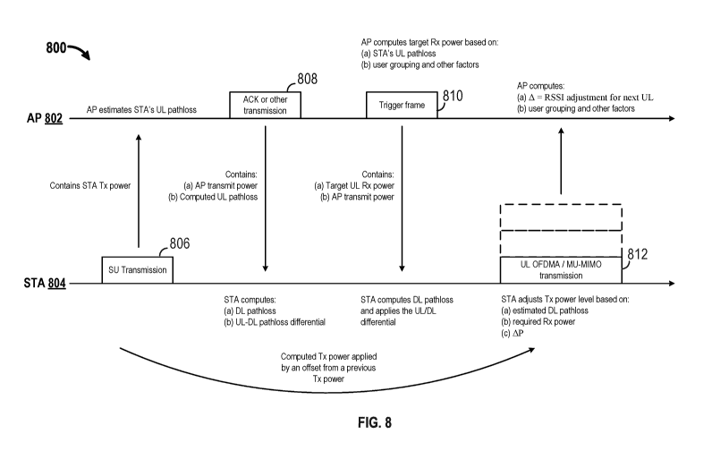
[0089] FIG. 8 illustrates an exemplary overview of a power control
mechanism with
calibration messages. Referring to FIG. 8, a STA 804 may send an AP 802 an SU
UL transmission 806 (e.g., a request to transmit message). The SU UL
transmission
806 may include the transmit power used by the STA 804 to transmit the SU UL
transmission 806. Upon receiving the SU UL transmission 806, the AP 802 may
estimate the STA's UL pathloss. Subsequently, the AP 802 may transmit a
downlink frame 808 (e.g., an ACK frame) to the STA 804. The downlink frame 808
may include the AP transmit power used to transmit the downlink frame 808
and/or
the computed UL pathloss. Upon receiving the downlink frame 808, the STA 804
may compute the downlink pathloss and compute the uplink and the downlink
pathloss differential. Subsequently, the AP 802 may compute a target RSSI or
target Rx power based on the STA's uplink pathloss, user grouping, and/or
other
factors. The AP 802 may transmit the computed targeted Rx power level to the
STA
804 in a trigger frame 810. The trigger frame 810 may also include the AP
transmit
power used to transmit the trigger frame 810. Upon receiving the trigger frame
810,
the STA 804 may compute the downlink pathloss and apply the UL/DL
differential.
Subsequently, the STA 804 may transmit data to the AP 802 in an uplink MU-
MIMO (or OFDMA) transmission 812. The STA 804 may transmit the data with an
adjusted Txt power level based on the estimated DL pathloss that has been
error
corrected and on the target Rx power level. In an aspect, for subsequent
transmissions, the adjusted Tx power level may further be adjusted if the AP
802
indicates a change in the target RSSI or in the Tx power level (e.g., AP) at
the STA
804.
[0090] The aforementioned paragraphs discussed various signaling
options for power
control in uplink transmissions. The tables below provide further detail on
the
CA 02993841 2018-01-25
WO 2017/040788
PCT/US2016/049910
various station capability signaling details. The details listed in Table 2
may be
signaled by the station during association with the AP.
[0091] Table 2. Station Capability Signaling
Parameter Value (Example) Comments
Max Tx power for each of the 20 dBm (or 24 dBm) Maximum STA transmit power
following RU sizes (# of tones): for a particular RU size
26-tone RU, 52-tone RU, 106-
tone RU, 242-tone RU, 484-
tone RU, 996-tone RU, 2x996-
tone RU)
Max Tx power for each 20 dBm (or 24 dBm) Maximum STA transmit power
bandwidth (e.g., 20 MHz, 40 for a particular bandwidth
MHz, 80 MHz, 160 MHz)
Max Tx power for each MCS 20 dBm (or 24 dBm) Maximum STA transmit power
for a particular MCS
Min Tx power -20 dBm Minimum STA transmit power
[0092]
Referring to Table 2, a maximum transmit power for each RU size, bandwidth,
and/or MCS may be indicated by a station according to the station's bandwidth
capability. An AP may need to know the limits of the station's transmit power
in
order to provide power control commands that may be applied at the station.
[0093] Table 3. Station Uplink Signaling
Parameter Range (Example) Comments
STA Tx power (per tone) 20 dBm to -20 dBm Tx power may include any
Range: 40 dB in 1 dB adjustments made, such as
increments MCS, meeting power spectral
density requirements, and/or
previous power
control
signaling
STA Tx power (per bandwidth) 20 dBm to -20 dBm Tx power may include any
Range: 40 dB in 1 dB adjustments made, such as
increments MCS, meeting power spectral
density requirements, and/or
previous power
control
signaling
[0094]
Referring to Table 3, in an uplink frame (e.g., the SU UL transmission 806), a
station may indicate the applied Tx power. An AP may use the applied Tx power
to
estimate the current pathloss for the STA based on the measured received power
of
the uplink frame at the STA.
[0095] Table 4. Access Point Downlink Signaling
Parameter Range (Example) Comments
Target Rx power -25 dBm to -85 dBm Expected Rx power from a
Range: 60 dBm in ldB STA. The STA computes the
increments Tx power based on DL
pathloss
measurements from a trigger
message.
Target Tx power -25 dBm to -85 dBm Instructed Tx power for a
STA.
26
CA 02993841 2018-01-25
WO 2017/040788
PCT/US2016/049910
Range: 60 dBm in ldB The STA utilizes the Tx power
increments without having to compute the
Tx power based on DL pathloss
measurements from a trigger
message.
AP Tx Power 20 dBm to -20 dBm Tx
power includes any
Range: 40 dB in 1 dB adjustments made such as MCS
increments and
meeting power spectral
density requirements.
[0096]
Referring to Table 4, in a downlink frame (e.g., the trigger frame 810), an AP
may indicate a target received power for a scheduled STA or a target transmit
power
to be used by the STA for uplink transmission. The downlink frame may include
an
AP transmit power applied to the downlink frame.
[0097] FIG. 9 shows an example functional block diagram of a wireless
device 902 that
may be employed within the wireless communication system 100 of FIG. 1. The
wireless device 902 is an example of a device that may be configured to
implement
the various methods described herein. For example, the wireless device 902 may
comprise the AP 104.
[0098] The wireless device 902 may include a processor 904 which
controls operation
of the wireless device 902. The processor 904 may also be referred to as a
central
processing unit (CPU). Memory 906, which may include both read-only memory
(ROM) and random access memory (RAM), may provide instructions and data to
the processor 904. A portion of the memory 906 may also include non-volatile
random access memory (NVRAM). The processor 904 typically performs logical
and arithmetic operations based on program instructions stored within the
memory
906. The instructions in the memory 906 may be executable (by the processor
904,
for example) to implement the methods described herein.
[0099] The processor 904 may comprise or be a component of a processing
system
implemented with one or more processors. The one or more processors may be
implemented with any combination of general-purpose microprocessors,
microcontrollers, digital signal processors (DSPs), field programmable gate
array
(FPGAs), programmable logic devices (PLDs), controllers, state machines, gated
logic, discrete hardware components, dedicated hardware finite state machines,
or
any other suitable entities that can perform calculations or other
manipulations of
information.
[00100] The processing system may also include machine-readable media
for storing
software. Software shall be construed broadly to mean any type of
instructions,
27
CA 02993841 2018-01-25
WO 2017/040788
PCT/US2016/049910
whether referred to as software, firmware, middleware, microcode, hardware
description language, or otherwise. Instructions may include code (e.g., in
source
code format, binary code format, executable code format, or any other suitable
format of code). The instructions, when executed by the one or more
processors,
cause the processing system to perform the various functions described herein.
[00101] The wireless device 902 may also include a housing 908, and the
wireless device
902 may include a transmitter 910 and/or a receiver 912 to allow transmission
and
reception of data between the wireless device 902 and a remote device. The
transmitter 910 and the receiver 912 may be combined into a transceiver 914.
An
antenna 916 may be attached to the housing 908 and electrically coupled to the
transceiver 914. The wireless device 902 may also include multiple
transmitters,
multiple receivers, multiple transceivers, and/or multiple antennas.
[00102] The wireless device 902 may also include a signal detector 918
that may be used
to detect and quantify the level of signals received by the transceiver 914 or
the
receiver 912. The signal detector 918 may detect such signals as total energy,
energy per subcarrier per symbol, power spectral density, and other signals.
The
wireless device 902 may also include a DSP 920 for use in processing signals.
The
DSP 920 may be configured to generate a packet for transmission. In some
aspects,
the packet may comprise a physical layer convergence protocol (PLCP) protocol
data unit (PPDU).
[00103] The wireless device 902 may further comprise a user interface
922 in some
aspects. The user interface 922 may comprise a keypad, a microphone, a
speaker,
and/or a display. The user interface 922 may include any element or component
that
conveys information to a user of the wireless device 902 and/or receives input
from
the user.
[00104] When the wireless device 902 is implemented as an AP (e.g., AP
104), the
wireless device 902 may also comprise a power control component 924. The power
control component 924 may be configured to determine a target receiver power
level
for uplink transmissions received at the wireless device 902. The power
control
component 924 may be configured to determine uplink power control information
930 based on the determined target receiver power level for UL MU-MIMO
transmission or UL OFDMA transmission. The power control component 924 may
be configured to transmit a frame that includes the determined uplink power
control
information 930 to a station scheduled by the wireless device 902 for uplink
28
CA 02993841 2018-01-25
WO 2017/040788
PCT/US2016/049910
transmission. In another configuration, the power control component 924 may be
configured to receive power control parameters 934 from the station. The power
control parameters may include at least one of a dynamic power range of the
station,
an absolute transmit power accuracy of the station, a relative transmit power
accuracy of the station, a transmit power step size of the station, a maximum
transmit power associated with one or more MCSs, a minimum transmit power
associated with the one or more MCSs, or a maximum transmit power associated
with one or more RU sizes, a minimum transmit power associated with one or
more
RU sizes. In an aspect, the uplink power control information may be determined
based on the received power control parameters. In another aspect, the uplink
power
control information may be determined based on one or more of an MCS to be
used
by each scheduled station, an uplink pathloss of each scheduled station, a
maximum
transmit power for each scheduled station, a minimum transmit power for each
scheduled station, a number of stations scheduled for uplink transmission on a
same
RU, a transmission history for each scheduled station, and an RU size. In
another
aspect, the determined uplink power control information controls uplink
transmit
power for a single station scheduled for transmission, for all stations
scheduled for
transmission, or for a subset stations scheduled for transmission. In another
aspect,
the determined uplink power control information may include the determined
target
receiver power level, a transmit power level, or a relative power level change
from a
previous transmission. In another aspect, the frame may further include a
downlink
transmit power for transmitting the frame, and the determined uplink power
control
information may include the determined target receiver power level. In another
aspect, the determined uplink power control information may include a transmit
power level based on a pathloss from the station to wireless device 902. In
another
aspect, the frame may be a trigger frame, and the determined uplink power
control
information is transmitted in the trigger frame. In another configuration, the
power
control component 924 may be configured to receive an UL SU transmission from
the station. The UL SU transmission may include a first transmit power used to
transmit the UL SU transmission. The power control component 924 may be
configured to estimate an uplink pathloss from the station based on the
received UL
SU transmission and to transmit a calibration message 932 to the station that
includes a second transmit power used to transmit the calibration message 932
and
the estimated uplink pathloss. The calibration message 932 may enable
computation
29
CA 02993841 2018-01-25
WO 2017/040788
PCT/US2016/049910
of an error correction factor. In another configuration, the power control
component
924 may be configured to transmit a message to the station. The message may
include a first transmit power used to transmit the message. The power control
component 924 may be configured to receive an acknowledgment message from the
station. The acknowledgment message may include a second transmit power used
to transmit the acknowledgment message and an estimated downlink pathloss
based
on the transmitted message. The power control component 924 may be configured
to estimate an error correction factor based on the received acknowledgment
message. In another configuration, the power control component 924 may be
configured to receive an UL MU MIMO transmission or an UL OFDMA
transmission from the station based on the determined uplink power control
information in the transmitted frame. In yet another configuration, the power
control component 924 may be configured to determine a difference between the
determined target receiver power level and a received power level of the UL MU
MIMO transmission or the UL OFDMA transmission. In this configuration, the
power control component 924 may be configured to adjust the target receiver
power
level based on the determined difference.
[00105] The various components of the wireless device 902 may be
coupled together by
a bus system 926. The bus system 926 may include a data bus, for example, as
well
as a power bus, a control signal bus, and a status signal bus in addition to
the data
bus. Components of the wireless device 902 may be coupled together or accept
or
provide inputs to each other using some other mechanism.
[00106] Although a number of separate components are illustrated in
FIG. 9, one or more
of the components may be combined or commonly implemented. For example, the
processor 904 may be used to implement not only the functionality described
above
with respect to the processor 904, but also to implement the functionality
described
above with respect to the signal detector 918, the DSP 920, the user interface
922,
and/or the power control component 924. Further, each of the components
illustrated in FIG. 9 may be implemented using a plurality of separate
elements.
[00107] FIGs. 10A and 10B are flowcharts of example methods 1000, 1050
of wireless
communication for power control by an access point. The methods 1000, 1050 may
be performed using an apparatus (e.g., the AP 104, the AP 202, the AP 302, the
AP
402, the AP 502, the AP 602, the AP 702, the AP 802, or the wireless device
902,
for example). Although the methods 1000, 1050 are described below with respect
to
CA 02993841 2018-01-25
WO 2017/040788
PCT/US2016/049910
the elements of wireless device 902 of FIG. 9, other components may be used to
implement one or more of the steps described herein. The dotted lines with
respect
to the various blocks represent optional blocks.
[00108] At block 1005, the apparatus may receive power control
parameters from a
station. For example, referring to FIG. 8, the apparatus may be the AP 802,
and the
station may be the STA 804. The AP 802 may receive power control parameters
from the STA 804. The power control parameters may include at least one of a
dynamic power range of the STA 804, an absolute transmit power accuracy of the
STA 804, a relative transmit power accuracy of the STA 804, a transmit power
step
size of the STA 804, a maximum transmit power associated with one or more MCSs
supported by the STA 804, a minimum transmit power associated with the one or
more MCSs supported by the STA 804, a maximum transmit power associated with
one or more RU sizes, or a minimum transmit power associated with one or more
RU sizes.
[00109] At block 1010, the apparatus may determine a target receiver
power level for
uplink transmissions received at the apparatus. For example, referring to FIG.
8, the
AP 802 may determine a target Rx power level for uplink transmissions received
at
the AP 802. In an example, the AP 802 may determine the target Rx power level
by
determining a number of STAs associated with the AP 802 and by determining the
number of RUs and/or the RU size on which the STAs are scheduled for
transmission to the AP 802. In an aspect, the determination may further be
based on
an uplink packet duration. In an aspect, the determination may also be based
on the
receiver implementation at the AP 802 such as inter-stream interference
management and certain SNR targets for different MCSs. Based on the foregoing,
the AP 802 may compute the target Rx power level for UL MU-MIMO or UL
OFDMA transmissions.
[00110] At block 1015, the apparatus may determine uplink power control
information
based on the determined target receiver power level for UL MU-MIMO
transmission or UL OFDMA transmission. For example, referring to FIG. 8, the
AP
802 may determine uplink power control information based on the determined
target
Rx power level by determining the dynamic power range of the STAs scheduled
for
transmission, including the STA 804, and by determining the maximum transmit
power level for one or more MCSs supported by the STAs. The AP 802 may
31
CA 02993841 2018-01-25
WO 2017/040788
PCT/US2016/049910
compute the target RSSI at the AP 802 or compute the Tx power level at the STA
804 and/or other STAs.
1001111 At block 1020, the apparatus may transmit a frame that includes
the determined
uplink power control information to a station scheduled by the access point
for
uplink transmission. For example, referring to FIG. 8, the AP 802 may transmit
the
trigger frame 810 that includes the target RSSI to the STA 804. The trigger
frame
810 may indicate the STA ID for the STA 804 and an allocated RU and/or RU size
indication for the STA 804. The trigger frame 810 may also indicate an MCS to
use
for uplink transmission.
[00112] At block 1025, the apparatus may receive an UL SU transmission
from the
station. The UL SU transmission may include a first transmit power used to
transmit the UL SU transmission. For example, referring to FIG. 8, the AP 802
may
receive the SU UL transmission 806 from the STA 804. The SU UL transmission
806 may include the first transmit power used by the STA 804 to transmit the
SU
UL transmission 806.
[00113] At block 1030, the apparatus may estimate an uplink pathloss
from the station
based on the received UL SU transmission. For example, referring to FIG. 8,
the
AP 802 may estimate the uplink pathloss from the STA 804 based on the received
SU UL transmission 806. The AP 802 may estimate the uplink pathloss by
measuring the received power of the SU UL transmission 806 and by subtracting
the
measured received power from the first transmit power indicated by the SU UL
transmission 806.
[00114] At block 1035, the apparatus may transmit a calibration message
to the station
that includes a second transmit power used to transmit the calibration message
and
the estimated uplink pathloss. The calibration message enables computation of
an
error correction factor. For example, referring to FIG. 8, the AP 802 may
transmit
the downlink frame 808 (the calibration message) to the STA 804. The downlink
frame 808 includes a second transmit power used by the AP 802 to transmit the
downlink frame 808 and the estimated uplink pathloss. The downlink frame 808
enables the STA 804 to compute a measurement error correction factor.
[00115] At block 1055, the apparatus may transmit a message to the
station. The
message may include a first transmit power used to transmit the message. For
example, referring to FIG. 7, the apparatus may be the AP 702, and the station
may
be the STA 704. The AP 702 may transmit the downlink frame 706 to the STA 704.
32
CA 02993841 2018-01-25
WO 2017/040788
PCT/US2016/049910
The downlink frame 706 may include a first transmit power used by the AP 702
to
transmit the downlink frame 706.
[00116] At block 1060, the apparatus may receive an acknowledgment
message from the
station. The acknowledgment message may include a second transmit power used
to transmit the acknowledgment message and an estimated downlink pathloss
based
on the transmitted message. For example, referring to FIG. 7, the AP 702 may
receive the uplink frame 708 (the acknowledgment message) from the STA 704.
The uplink frame 708 may include a second transmit power used by the STA 704
to
transmit the uplink frame 708. The uplink frame 708 may include the estimated
downlink pathloss calculated by the STA 704 based on the downlink frame 706.
[00117] At block 1065, the apparatus may estimate an error correction
factor based on
the received acknowledgment message. For example, referring to FIG. 7, the AP
702 may estimate the error correction factor based on the received uplink
frame 708.
The AP 702 may estimate the error correction factor by determining the uplink
pathloss based on the received uplink frame 708 and by taking the difference
between the estimated downlink pathloss and the determined uplink pathloss.
[00118] At block 1070, the apparatus may receive an UL MU MIMO
transmission or an
UL OFDMA transmission from the station based on the determined uplink power
control information in the transmitted frame. For example, referring to FIG.
8, the
AP 802 may receive an UL MU-MIMO transmission 812 from the STA 804 based
on the determined uplink power control information in the trigger frame 810.
[00119] At block 1075, the apparatus may determine a difference between
the
determined target receiver power level and a received power level of the UL MU
MIMO transmission or the UL OFDMA transmission. For example, referring to
FIG. 8, the AP 802 may determine a difference between the determined target
receiver power level and the received power level of the UL MU-MIMO
transmission 812. The AP 802 may determine the difference by measuring the
received power level of the UL MU-MIMO transmission 812 and by taking the
difference between the determined target receiver power level and the received
power level of the UL MU-MIMO transmission 812.
[00120] At block 1080, the apparatus may adjust the target receiver
power level based on
the determined difference. For example, referring to FIG. 8, the AP 802 may
adjust
the target receiver power level based on the determined difference. That is,
the AP
802 may increase the target receiver power level based on the difference if
the
33
CA 02993841 2018-01-25
WO 2017/040788
PCT/US2016/049910
measured power level is less than the target receiver power level, or the AP
802 may
decrease the target receiver power level if the measured power level is
greater than
the target receiver power level. In another aspect, the AP 802 may determine
not to
adjust the target receiver power level if the measured power level is within a
threshold of the target receiver power level.
[00121] FIG. 11 is a functional block diagram of an example wireless
communication
device 1100 configured for power control. The wireless communication device
1100 may include a receiver 1105, a processing system 1110, and a transmitter
1115. The processing system 1110 may include a power control component 1124.
The processing system 1110 and/or the power control component 1124 may be
configured to determine a target receiver power level for uplink transmissions
received at the wireless communication device 1100. The processing system 1110
and/or the power control component 1124 may be configured to determine uplink
power control information 1132 based on the determined target receiver power
level
for UL MU-MIMO transmission or UL OFDMA transmission. The transmitter
1115, processing system 1110, and/or the power control component 1124 may be
configured to transmit a frame that includes the determined uplink power
control
information to a station scheduled by the wireless communication device 1100
for
uplink transmission. In another configuration, the receiver 1105, processing
system
1110, and/or the power control component 1124 may be configured to receive
power
control parameters 1130 from the station. The power control parameters 1130
may
include at least one of a dynamic power range of the station, an absolute
transmit
power accuracy of the station, a relative transmit power accuracy of the
station, a
transmit power step size of the station, a maximum transmit power associated
with
one or more MCSs, a minimum transmit power associated with the one or more
MCSs, or a maximum transmit power associated with one or more RU sizes, a
minimum transmit power associated with one or more RU sizes. In an aspect, the
uplink power control information may be determined based on the received power
control parameters. In another aspect, the uplink power control information
may be
determined based on one or more of an MCS to be used by each scheduled
station,
an uplink pathloss of each scheduled station, a maximum transmit power for
each
scheduled station, a minimum transmit power for each scheduled station, a
number
of stations scheduled for uplink transmission on a same RU, a transmission
history
for each scheduled station, and an RU size. In another aspect, the determined
uplink
34
CA 02993841 2018-01-25
WO 2017/040788
PCT/US2016/049910
power control information controls uplink transmit power for a single station
scheduled for transmission, for all stations scheduled for transmission, or
for a
subset stations scheduled for transmission. In another aspect, the determined
uplink
power control information may include the determined target receiver power
level, a
transmit power level, or a relative power level change from a previous
transmission.
In another aspect, the frame may further include a downlink transmit power for
transmitting the frame, and the determined uplink power control information
may
include the determined target receiver power level. In another aspect, the
determined uplink power control information may include a transmit power level
based on a pathloss from the station to the wireless communication device
1100. In
another aspect, the frame may be a trigger frame, and the determined uplink
power
control information is transmitted in the trigger frame. In another
configuration, the
receiver 1105, the processing system 1110 and/or the power control component
1124 may be configured to receive an UL SU transmission from the station. The
UL SU transmission may include a first transmit power used to transmit the UL
SU
transmission. The processing system 1110 and/or the power control component
1124 may be configured to estimate an uplink pathloss from the station based
on the
received UL SU transmission and to transmit a calibration message 1134 to the
station that includes a second transmit power used to transmit the calibration
message 1134 and the estimated uplink pathloss. The calibration message 1134
may
enable computation of an error correction factor. In another configuration,
the
transmitter 1115, the processing system 1110, and/or the power control
component
1124 may be configured to transmit a message to the station. The message may
include a first transmit power used to transmit the message. The receiver
1105, the
processing system 1110, and/or the power control component 1124 may be
configured to receive an acknowledgment message from the station. The
acknowledgment message may include a second transmit power used to transmit
the
acknowledgment message and an estimated downlink pathloss based on the
transmitted message. The processing system 1110 and/or the power control
component 1124 may be configured to estimate an error correction factor based
on
the received acknowledgment message. In another configuration, the receiver
1105,
the processing system 1110, and/or the power control component 1124 may be
configured to receive an UL MU MIMO transmission or an UL OFDMA
transmission from the station based on the determined uplink power control
CA 02993841 2018-01-25
WO 2017/040788
PCT/US2016/049910
information in the transmitted frame. In yet another configuration, the
processing
system 1110 and/or the power control component 1124 may be configured to
determine a difference between the determined target receiver power level and
a
received power level of the UL MU MIMO transmission or the UL OFDMA
transmission. In this configuration, the processing system 1110 and/or the
power
control component 1124 may be configured to adjust the target receiver power
level
based on the determined difference.
[00122] The receiver 1105, the processing system 1110, the power
control component
1124, and/or the transmitter 1115 may be configured to perform one or more
functions discussed above with respect to blocks 1005, 1010, 1015, 1020, 1025,
1030, 1035, 1055, 1060, 1065, 1070, 1075, and 1080 of FIGs. 10A and 10B. The
receiver 1105 may correspond to the receiver 912. The processing system 1110
may
correspond to the processor 904. The transmitter 1115 may correspond to the
transmitter 910. The power control component 1124 may correspond to the power
control component 124 and/or the power control component 924.
[00123] In one configuration, the wireless communication device 1100
includes means
for determining a target receiver power level for uplink transmissions
received at the
wireless communication device 1100. The uplink power control information may
be
determined based on the determined target receiver power level for UL MU-MIMO
transmission or UL OFDMA transmission. The wireless communication device
1100 may include means for transmitting a frame that includes the determined
uplink power control information to a station scheduled by the wireless
communication device 1100 for uplink transmission. In another configuration,
the
wireless communication device 1100 may include means for receiving power
control parameters from the station. The power control parameters may include
at
least one of a dynamic power range of the station, an absolute transmit power
accuracy of the station, a relative transmit power accuracy of the station, a
transmit
power step size of the station, a maximum transmit power associated with one
or
more MCSs, a minimum transmit power associated with the one or more MCSs, or a
maximum transmit power associated with one or more RU sizes, a minimum
transmit power associated with one or more RU sizes. In an aspect, the uplink
power control information may be determined based on the received power
control
parameters. In another aspect, the uplink power control information may be
determined based on one or more of an MCS to be used by each scheduled
station,
36
CA 02993841 2018-01-25
WO 2017/040788
PCT/US2016/049910
an uplink pathloss of each scheduled station, a maximum transmit power for
each
scheduled station, a minimum transmit power for each scheduled station, a
number
of stations scheduled for uplink transmission on a same RU, a transmission
history
for each scheduled station, and an RU size. In another aspect, the determined
uplink
power control information controls uplink transmit power for a single station
scheduled for transmission, for all stations scheduled for transmission, or
for a
subset stations scheduled for transmission. In another aspect, the determined
uplink
power control information may include the determined target receiver power
level, a
transmit power level, or a relative power level change from a previous
transmission.
In another aspect, the frame may further include a downlink transmit power for
transmitting the frame, and the determined uplink power control information
may
include the determined target receiver power level. In another aspect, the
determined uplink power control information may include a transmit power level
based on a pathloss from the station to wireless communication device 1100. In
another aspect, the frame may be a trigger frame, and the determined uplink
power
control information is transmitted in the trigger frame. In another
configuration, the
wireless communication device 1100 may include means for receiving an UL SU
transmission from the station. The UL SU transmission may include a first
transmit
power used to transmit the UL SU transmission. The wireless communication
device 1100 may include means for estimating an uplink pathloss from the
station
based on the received UL SU transmission and to transmit a calibration message
to
the station that includes a second transmit power used to transmit the
calibration
message and the estimated uplink pathloss. The calibration message may enable
computation of an error correction factor. In another configuration, the
wireless
communication device 1100 may include means for transmitting a message to the
station. The message may include a first transmit power used to transmit the
message. The wireless communication device 1100 may include means for
receiving an acknowledgment message from the station. The acknowledgment
message may include a second transmit power used to transmit the
acknowledgment
message and an estimated downlink pathloss based on the transmitted message.
The
wireless communication device 1100 may include means for estimating an error
correction factor based on the received acknowledgment message. In another
configuration, the wireless communication device 1100 may include means for
receiving an UL MU MIMO transmission or an UL OFDMA transmission from the
37
CA 02993841 2018-01-25
WO 2017/040788
PCT/US2016/049910
station based on the determined uplink power control information in the
transmitted
frame. In yet another configuration, the wireless communication device 1100
may
include means for determining a difference between the determined target
receiver
power level and a received power level of the UL MU MIMO transmission or the
UL OFDMA transmission. In this configuration, the target receiver power level
may be adjusted based on the determined difference.
[00124] For example, means for determining a target receiver power
level may include
the processing system 1110 and/or the power control component 1124. Means for
determining uplink power control information may include the processing system
1110 and/or the power control component 1124. Means for transmitting the frame
may include the transmitter 1115, processing system 1110, and/or the power
control
component 1124. Means for receiving an uplink SU transmission may include the
receiver 1105, the processing system 1110, and/or the power control component
1124. Means for estimating the uplink pathloss may include the processing
system
1110 and/or the power control component 1124. Means for transmitting a
calibration message may include the transmitter 1115, the processing system
1110,
and/or the power control component 1124. Means for transmitting a message to
the
station may include the transmitter 1115, the processing system 1110, and/or
the
power control component 1124. Means for receiving an acknowledgment message
from the station may include the receiver 1105, the processing system 1110,
and/or
the power control component 1124. Means for estimating an error correction
factor
may include the processing system 1110 and/or the power control component
1124.
Means for receiving an UL MU MIMO transmission or an UL OFDMA
transmission may include the receiver 1105, the processing system 1110, and/or
the
power control component 1124. Means for determining a difference may include
the processing system 1110 and/or the power control component 1124. Means for
adjusting the target receiver power level may include the processing system
1110
and/or the power control component 1124.
[00125] FIG. 12 shows an example functional block diagram of a wireless
device 1202
that may be employed within the wireless communication system 100 of FIG. 1.
The wireless device 1202 is an example of a device that may be configured to
implement the various methods described herein. For example, the wireless
device
1202 may comprise the STA 114.
38
CA 02993841 2018-01-25
WO 2017/040788
PCT/US2016/049910
[00126] The
wireless device 1202 may include a processor 1204 which controls
operation of the wireless device 1202. The processor 1204 may also be referred
to
as a CPU. Memory 1206, which may include both ROM and RAM, may provide
instructions and data to the processor 1204. A portion of the memory 1206 may
also
include NVRAM. The processor 1204 typically performs logical and arithmetic
operations based on program instructions stored within the memory 1206. The
instructions in the memory 1206 may be executable (by the processor 1204, for
example) to implement the methods described herein.
[00127] The processor 1204 may comprise or be a component of a
processing system
implemented with one or more processors. The one or more processors may be
implemented with any combination of general-purpose microprocessors,
microcontrollers, DSPs, FPGAs, PLDs, controllers, state machines, gated logic,
discrete hardware components, dedicated hardware finite state machines, or any
other suitable entities that can perform calculations or other manipulations
of
information.
[00128] The processing system may also include machine-readable media
for storing
software. Software shall be construed broadly to mean any type of
instructions,
whether referred to as software, firmware, middleware, microcode, hardware
description language, or otherwise. Instructions may include code (e.g., in
source
code format, binary code format, executable code format, or any other suitable
format of code). The instructions, when executed by the one or more
processors,
cause the processing system to perform the various functions described herein.
[00129] The wireless device 1202 may also include a housing 1208, and
the wireless
device 1202 may include a transmitter 1210 and/or a receiver 1212 to allow
transmission and reception of data between the wireless device 1202 and a
remote
device. The transmitter 1210 and the receiver 1212 may be combined into a
transceiver 1214. An antenna 1216 may be attached to the housing 1208 and
electrically coupled to the transceiver 1214. The wireless device 1202 may
also
include multiple transmitters, multiple receivers, multiple transceivers,
and/or
multiple antennas.
[00130] The wireless device 1202 may also include a signal detector
1218 that may be
used to detect and quantify the level of signals received by the transceiver
1214 or
the receiver 1212. The signal detector 1218 may detect such signals as total
energy,
energy per subcarrier per symbol, power spectral density, and other signals.
The
39
CA 02993841 2018-01-25
WO 2017/040788
PCT/US2016/049910
wireless device 1202 may also include a DSP 1220 for use in processing
signals.
The DSP 1220 may be configured to generate a packet for transmission. In some
aspects, the packet may comprise a PPDU.
[00131] The wireless device 1202 may further comprise a user interface
1222 in some
aspects. The user interface 1222 may comprise a keypad, a microphone, a
speaker,
and/or a display. The user interface 1222 may include any element or component
that conveys information to a user of the wireless device 1202 and/or receives
input
from the user.
[00132] When the wireless device 1202 is implemented as a station
(e.g., STA 114), the
wireless device 1202 may also comprise a power control component 1224. The
power control component 1224 may be configured to receive a frame from an
access
point. The frame may include uplink power control information 1232, associated
with a target receiver power level at the access point, for UL MU-MIMO
transmission or UL OFDMA transmission. The power control component 1224 may
be configured to determine a transmit power based on the received uplink power
control information and to transmit a second frame to the access point based
on the
determined transmit power. In another configuration, the power control
component
1224 may be configured to transmit power control parameters 1230 to the access
point. The power control parameters may include at least one of a dynamic
power
range of the station, an absolute transmit power accuracy of the station, a
relative
transmit power accuracy of the station, a transmit power step size of the
station, a
maximum transmit power associated with one or more MCSs, a minimum transmit
power associated with the one or more MCSs, a maximum transmit power
associated with one or more RU sizes, or a minimum transmit power associated
with
one or more RU sizes. The received uplink power control information may be
based
on the transmitted power control parameters. In an aspect, the determined
uplink
power control information may include the determined target receiver power
level, a
transmit power level, or a relative power level change from a previous
transmission.
In another aspect, the frame may further include a downlink transmit power
used to
transmit the frame, and the determined uplink power control information may
include the determined target receiver power level. In another aspect, the
frame may
be a trigger frame, and the determined uplink power control information may be
received in the trigger frame. In another aspect, the power control component
1224
may be configured to determine the transmit power by determining a pathloss
CA 02993841 2018-01-25
WO 2017/040788
PCT/US2016/049910
between the wireless device 1202 and the access point based on a downlink
transmit
power indicated in the received frame and to compute the transmit power based
on
the determined pathloss and the uplink power control information. In another
aspect, the determined uplink power control information may include a transmit
power level based on a pathloss from the wireless device 1202 to the access
point.
The transmit power may be equal to the transmit power level. In another
aspect, the
determined uplink power control information may include a relative power
change
from the previous transmission by the wireless device 1202, and the transmit
power
may be adjusted based on the relative power change. In another configuration,
the
power control component 1224 may be configured to transmit an UL SU
transmission to the access point. The UL SU transmission may include a first
transmit power used to transmit the UL SU transmission. The power control
component 1224 may be configured to receive a calibration message 1234 from
the
access point that includes a second transmit power used to transmit the
calibration
message 1234 and an estimated uplink pathloss based on the transmitted UL SU
transmission. The power control component 1224 may be configured to compute an
error correction factor based on the received calibration message 1234. In
another
configuration, the power control component 1224 may be configured to receive a
message from the access point. The message may include a first transmit power
used to transmit the message. The power control component 1224 may be
configured to transmit an acknowledgment message to the access point. The
acknowledgment message may include a second transmit power used to transmit
the
acknowledgment message and an estimated downlink pathloss based on the
transmitted message.
[00133] The various components of the wireless device 1202 may be
coupled together by
a bus system 1226. The bus system 1226 may include a data bus, for example, as
well as a power bus, a control signal bus, and a status signal bus in addition
to the
data bus. Components of the wireless device 1202 may be coupled together or
accept or provide inputs to each other using some other mechanism.
[00134] Although a number of separate components are illustrated in
FIG. 12, one or
more of the components may be combined or commonly implemented. For
example, the processor 1204 may be used to implement not only the
functionality
described above with respect to the processor 1204, but also to implement the
functionality described above with respect to the signal detector 1218, the
DSP
41
CA 02993841 2018-01-25
WO 2017/040788
PCT/US2016/049910
1220, the user interface 1222, and/or the power control component 1224.
Further,
each of the components illustrated in FIG. 12 may be implemented using a
plurality
of separate elements.
[00135] FIG. 13 is a flowchart of an example method 1300 of wireless
communication
for power control by a station. The method 1300 may be performed using an
apparatus (e.g., the STA 114, the STA 204, the STA 304, the STA 404, the STA
504, the STA 604, the STA 704, the STA 804, or the wireless device 1202, for
example). Although the method 1300 is described below with respect to the
elements of wireless device 1202 of FIG. 12, other components may be used to
implement one or more of the steps described herein. The dotted lines with
respect
to the various blocks represent optional blocks.
[00136] At block 1305, the apparatus may transmit power control
parameters to an
access point. For example, referring to FIG. 8, the apparatus may be a STA 804
and
the access point may be the AP 802. The STA 804 may transmit power control
parameters to the AP 802. The power control parameters may include at least
one of
a dynamic power range of the STA 804, an absolute transmit power accuracy of
the
STA 804, a relative transmit power accuracy of the STA 804, a transmit power
step
size of the STA 804, a maximum transmit power associated with one or more
MCSs, a minimum transmit power associated with the one or more MCSs, a
maximum transmit power associated with one or more RU sizes, or a minimum
transmit power associated with one or more RU sizes.
[00137] At block 1310, the apparatus may receive a frame from the
access point. The
frame may include uplink power control information, associated with a target
receiver power level at the access point, for UL MU-MIMO transmission or UL
OFDMA transmission. For example, referring to FIG. 8, the STA 804 may receive
the trigger frame 810 (the frame) from the AP 802. The trigger frame 810 may
include uplink power control information, associated with the target receiver
power
level at the AP 802, for UL MU-MIMO transmission or UL OFDMA transmission.
[00138] At block 1315, the apparatus may determine a transmit power
based on the
received uplink power control information. For example, referring to FIG. 8,
the
STA 804 may determine the transmit power based on the received uplink power
control information. In one aspect, if the uplink power control information
contains
the transmit power level, then the STA 804 may determine the transmit power by
using the transmit power level indicated by the uplink power control
information. In
42
CA 02993841 2018-01-25
WO 2017/040788
PCT/US2016/049910
another aspect, if the uplink power control information contains a target
receiver
power level, then the STA 804 may determine the pathloss between the STA 804
and the AP 802 and add the pathloss to the target receiver power level, in
which the
sum may be the transmit power. In another aspect, if the uplink power control
information contains a relative power level change, then the STA 804 may
adjust the
previous transmit power based on the relative power level change.
[00139] At block 1320, the apparatus may transmit a second frame to the
access point
based on the determined transmit power. For example, referring to FIG. 8, the
STA
804 may transmit a second frame to the AP 802 based on the determined transmit
power.
[00140] At block 1325, the apparatus may transmit an UL SU transmission
to the access
point. The UL SU transmission may include a first transmit power used to
transmit
the UL SU transmission. For example, referring to FIG. 8, the STA 804 may
transmit the SU UL transmission 806 to the AP 802. The SU UL transmission 806
may include a first transmit power used by the STA 804 to transmit the SU UL
transmission 806.
[00141] At block 1330, the apparatus may receive a calibration message
from the access
point that includes a second transmit power used to transmit the calibration
message
and an estimated uplink pathloss based on the transmitted UL SU transmission.
For
example, referring to FIG. 8, the STA 804 may receive the downlink frame 808
(the
calibration message) from the AP 802 that includes a second transmit power
used by
the AP 802 to transmit the downlink frame 808. The downlink frame 808 may also
include an estimated uplink pathloss based on the SU UL transmission 806.
[00142] At block 1335, the apparatus may compute an error correction
factor based on
the received calibration message. For example, referring to FIG. 8, the STA
804
may compute an error correction factor based on the received downlink frame
808.
The STA 804 may compute the error correction factor by determining the
downlink
pathloss from the AP 802 based on the downlink frame 808. The STA 804 may
determine the difference between the downlink pathloss and the uplink pathloss
received in the downlink frame 808, in which the difference between the
pathlosses
may be considered the error correction factor.
[00143] At block 1340, the apparatus may receive a message from the
access point. The
message may include a first transmit power used to transmit the message. For
example, referring to FIG. 7, the apparatus may be the STA 704 and the access
point
43
CA 02993841 2018-01-25
WO 2017/040788
PCT/US2016/049910
may be the AP 702. The STA 704 may receive the downlink frame 706 (the
message) from the AP 702. The downlink frame 706 may include a first transmit
power used by the AP 702 to transmit the downlink frame 706.
[00144] At block 1345, the apparatus may transmit an acknowledgment
message to the
access point. The acknowledgment message may include a second transmit power
used to transmit the acknowledgment message and an estimated downlink pathloss
based on the transmitted message. For example, referring to FIG. 7, the STA
704
may transmit the uplink frame 708 to the AP 702. The uplink frame 708 may
include a second transmit power used by the STA 704 to transmit the uplink
frame
708. The uplink frame 708 may further include an estimated downlink pathloss
based on the downlink frame 706.
[00145] FIG. 14 is a functional block diagram of an example wireless
communication
device 1400 configured for power control. The wireless communication device
1400 may include a receiver 1405, a processing system 1410, and a transmitter
1415. The processing system 1410 may include a power control component 1424.
The receiver 1405, the processing system 1410, and/or the power control
component
1424 may be configured to receive a frame from an access point. The frame may
include uplink power control information 1430, associated with a target
receiver
power level at the access point, for UL MU-MIMO transmission or UL OFDMA
transmission. The processing system 1410 and/or the power control component
1424 may be configured to determine a transmit power based on the received
uplink
power control information and to transmit a second frame to the access point
based
on the determined transmit power. In another configuration, the transmitter
1415,
the processing system 1410, and/or the power control component 1424 may be
configured to transmit power control parameters 1434 to the access point. The
power control parameters may include at least one of a dynamic power range of
the
wireless communication device 1400, an absolute transmit power accuracy of the
wireless communication device 1400, a relative transmit power accuracy of the
wireless communication device 1400, a transmit power step size of the wireless
communication device 1400, a maximum transmit power associated with one or
more MCSs, a minimum transmit power associated with the one or more MCSs, a
maximum transmit power associated with one or more RU sizes, or a minimum
transmit power associated with one or more RU sizes. The received uplink power
control information may be based on the transmitted power control parameters.
In
44
CA 02993841 2018-01-25
WO 2017/040788
PCT/US2016/049910
an aspect, the determined uplink power control information may include the
determined target receiver power level, a transmit power level, or a relative
power
level change from a previous transmission. In another aspect, the frame may
further
include a downlink transmit power used to transmit the frame, and the
determined
uplink power control information may include the determined target receiver
power
level. In another aspect, the frame may be a trigger frame, and the determined
uplink power control information may be received in the trigger frame. In
another
aspect, the processing system 1410 and/or the power control component 1424 may
be configured to determine the transmit power by determining a pathloss
between
the wireless communication device 1400 and the access point based on a
downlink
transmit power indicated in the received frame and to compute the transmit
power
based on the determined pathloss and the uplink power control information. In
another aspect, the determined uplink power control information may include a
transmit power level based on a pathloss from the wireless communication
device
1400 to the access point. The transmit power may be equal to the transmit
power
level. In another aspect, the determined uplink power control information may
include a relative power change from the previous transmission by the wireless
communication device 1400, and the transmit power may be adjusted based on the
relative power change. In
another configuration, the transmitter 1415, the
processing system 1410, and/or the power control component 1424 may be
configured to transmit an UL SU transmission to the access point. The UL SU
transmission may include a first transmit power used to transmit the UL SU
transmission. The receiver 1405, the processing system 1410, and/or the power
control component 1424 may be configured to receive a calibration message 1432
from the access point that includes a second transmit power used to transmit
the
calibration message 1432 and an estimated uplink pathloss based on the
transmitted
UL SU transmission. The processing system 1410 and/or the power control
component 1424 may be configured to compute an error correction factor based
on
the received calibration message 1432. In another configuration, receiver
1405, the
processing system 1410, and/or the power control component 1424 may be
configured to receive a message from the access point. The message may include
a
first transmit power used to transmit the message. The transmitter 1415, the
processing system 1410, and/or the power control component 1424 may be
configured to transmit an acknowledgment message to the access point. The
CA 02993841 2018-01-25
WO 2017/040788
PCT/US2016/049910
acknowledgment message may include a second transmit power used to transmit
the
acknowledgment message and an estimated downlink pathloss based on the
transmitted message.
[00146] The receiver 1405, the processing system 1410, the power
control component
1424, and/or the transmitter 1415 may be configured to perform one or more
functions discussed above with respect to blocks 1305, 1310, 1315, 1320, 1325,
1330, 1335, 1340, and 1345 of FIG. 13. The receiver 1405 may correspond to the
receiver 1212. The processing system 1410 may correspond to the processor
1204.
The transmitter 1415 may correspond to the transmitter 1210. The power control
component 1424 may correspond to the power control component 126 and/or the
power control component 1224.
[00147] In one configuration, the wireless communication device 1400
may include
means for receiving a frame from an access point. The frame may include uplink
power control information, associated with a target receiver power level at
the
access point, for UL MU-MIMO transmission or UL OFDMA transmission. The
wireless communication device 1400 may include means for determining a
transmit
power based on the received uplink power control information and means for
transmitting a second frame to the access point based on the determined
transmit
power. In another configuration, the wireless communication device 1400 may
include means for transmitting power control parameters to the access point.
The
power control parameters may include at least one of a dynamic power range of
the
wireless communication device 1400, an absolute transmit power accuracy of the
wireless communication device 1400, a relative transmit power accuracy of the
wireless communication device 1400, a transmit power step size of the wireless
communication device 1400, a maximum transmit power associated with one or
more MCSs, a minimum transmit power associated with the one or more MCSs, a
maximum transmit power associated with one or more RU sizes, or a minimum
transmit power associated with one or more RU sizes. The received uplink power
control information may be based on the transmitted power control parameters.
In
an aspect, the determined uplink power control information may include the
determined target receiver power level, a transmit power level, or a relative
power
level change from a previous transmission. In another aspect, the frame may
further
include a downlink transmit power used to transmit the frame, and the
determined
uplink power control information may include the determined target receiver
power
46
CA 02993841 2018-01-25
WO 2017/040788
PCT/US2016/049910
level. In another aspect, the frame may be a trigger frame, and the determined
uplink power control information may be received in the trigger frame. In
another
aspect, means for determining the transmit power may be configured to
determine a
pathloss between the wireless communication device 1400 and the access point
based on a downlink transmit power indicated in the received frame and to
compute
the transmit power based on the determined pathloss and the uplink power
control
information. In another aspect, the determined uplink power control
information
may include a transmit power level based on a pathloss from the wireless
communication device 1400 to the access point. The transmit power may be equal
to
the transmit power level. In another aspect, the determined uplink power
control
information may include a relative power change from the previous transmission
by
the wireless communication device 1400, and the transmit power may be adjusted
based on the relative power change. In another configuration, the wireless
communication device 1400 may include means for transmitting an UL SU
transmission to the access point. The UL SU transmission may include a first
transmit power used to transmit the UL SU transmission. The
wireless
communication device 1400 may include means for receiving a calibration
message
from the access point that includes a second transmit power used to transmit
the
calibration message and an estimated uplink pathloss based on the transmitted
UL
SU transmission. The wireless communication device 1400 may include means for
computing an error correction factor based on the received calibration
message. In
another configuration, the wireless communication device 1400 may include
means
for receiving a message from the access point. The message may include a first
transmit power used to transmit the message. The wireless communication device
1400 may include means for transmitting an acknowledgment message to the
access
point. The acknowledgment message may include a second transmit power used to
transmit the acknowledgment message and an estimated downlink pathloss based
on
the transmitted message.
[00148] For example, means for receiving a frame may include the
receiver 1405, the
processing system 1410, and/or the power control component 1424. Means for
determining a transmit power may include the processing system 1410 and/or the
power control component 1424. Means for transmitting a second frame may
include
the transmitter 1415, the processing system 1410, and/or the power control
component 1424. Means for transmitting power control parameters may include
the
47
CA 02993841 2018-01-25
WO 2017/040788
PCT/US2016/049910
transmitter 1415, the processing system 1410, and/or the power control
component
1424. Means for transmitting an UL SU transmission may include the transmitter
1415, the processing system 1410, and/or the power control component 1424.
Means for receiving a calibration message may include the receiver 1405, the
processing system 1410, and/or the power control component 1424. Means for
computing an error correction factor may include the processing system 1410
and/or
the power control component 1424. Means for receiving a message from the
access
point may include the receiver 1405, the processing system 1410, and/or the
power
control component 1424. Means for transmitting an acknowledgment message may
include the transmitter 1415, the processing system 1410, and/or the power
control
component 1424.
[00149] The various operations of methods described above may be
performed by any
suitable means capable of performing the operations, such as various hardware
and/or software component(s), circuits, and/or module(s). Generally, any
operations
illustrated in the Figures may be performed by corresponding functional means
capable of performing the operations.
[00150] The various illustrative logical blocks, components and
circuits described in
connection with the present disclosure may be implemented or performed with a
general purpose processor, a DSP, an application specific integrated circuit
(ASIC),
an FPGA or other PLD, discrete gate or transistor logic, discrete hardware
components or any combination thereof designed to perform the functions
described
herein. A general purpose processor may be a microprocessor, but in the
alternative,
the processor may be any commercially available processor, controller,
microcontroller or state machine. A processor may also be implemented as a
combination of computing devices, e.g., a combination of a DSP and a
microprocessor, a plurality of microprocessors, one or more microprocessors in
conjunction with a DSP core, or any other such configuration.
[00151] In one or more aspects, the functions described may be
implemented in
hardware, software, firmware, or any combination thereof If implemented in
software, the functions may be stored on or transmitted over as one or more
instructions or code on a computer-readable medium. Computer-readable media
includes both computer storage media and communication media including any
medium that facilitates transfer of a computer program from one place to
another. A
storage media may be any available media that can be accessed by a computer.
By
48
CA 02993841 2018-01-25
WO 2017/040788
PCT/US2016/049910
way of example, and not limitation, such computer-readable media can comprise
RAM, ROM, EEPROM, compact disk (CD)-ROM (CD-ROM) or other optical disk
storage, magnetic disk storage or other magnetic storage devices, or any other
medium that can be used to carry or store desired program code in the form of
instructions or data structures and that can be accessed by a computer. Also,
any
connection is properly termed a computer-readable medium. For example, if the
software is transmitted from a website, server, or other remote source using a
coaxial cable, fiber optic cable, twisted pair, digital subscriber line (DSL),
or
wireless technologies such as infrared, radio, and microwave, then the coaxial
cable,
fiber optic cable, twisted pair, DSL, or wireless technologies such as
infrared, radio,
and microwave are included in the definition of medium. Disk and disc, as used
herein, includes CD, laser disc, optical disc, digital versatile disc (DVD),
floppy
disk and Blu-ray disc where disks usually reproduce data magnetically, while
discs
reproduce data optically with lasers. Thus, computer readable medium comprises
a
non-transitory computer readable medium (e.g., tangible media).
[00152] The methods disclosed herein comprise one or more steps or
actions for
achieving the described method. The method steps and/or actions may be
interchanged with one another without departing from the scope of the claims.
In
other words, unless a specific order of steps or actions is specified, the
order and/or
use of specific steps and/or actions may be modified without departing from
the
scope of the claims.
[00153] Thus, certain aspects may comprise a computer program product
for performing
the operations presented herein. For example, such a computer program product
may comprise a computer readable medium having instructions stored (and/or
encoded) thereon, the instructions being executable by one or more processors
to
perform the operations described herein. For certain aspects, the computer
program
product may include packaging material.
[00154] Further, it should be appreciated that components and/or other
appropriate
means for performing the methods and techniques described herein can be
downloaded and/or otherwise obtained by a user terminal and/or base station as
applicable. For example, such a device can be coupled to a server to
facilitate the
transfer of means for performing the methods described herein. Alternatively,
various methods described herein can be provided via storage means (e.g., RAM,
ROM, a physical storage medium such as a CD or floppy disk, etc.), such that a
user
49
CA 02993841 2018-01-25
WO 2017/040788
PCT/US2016/049910
terminal and/or base station can obtain the various methods upon coupling or
providing the storage means to the device. Moreover, any other suitable
technique
for providing the methods and techniques described herein to a device can be
utilized.
[00155] It is to be understood that the claims are not limited to the
precise configuration
and components illustrated above. Various modifications, changes and
variations
may be made in the arrangement, operation and details of the methods and
apparatus
described above without departing from the scope of the claims.
[00156] While the foregoing is directed to aspects of the present
disclosure, other and
further aspects of the disclosure may be devised without departing from the
basic
scope thereof, and the scope thereof is determined by the claims that follow.
[00157] The previous description is provided to enable any person
skilled in the art to
practice the various aspects described herein. Various modifications to these
aspects
will be readily apparent to those skilled in the art, and the generic
principles defined
herein may be applied to other aspects. Thus, the claims are not intended to
be
limited to the aspects shown herein, but is to be accorded the full scope
consistent
with the language claims, wherein reference to an element in the singular is
not
intended to mean "one and only one" unless specifically so stated, but rather
"one or
more." Unless specifically stated otherwise, the term "some" refers to one or
more.
All structural and functional equivalents to the elements of the various
aspects
described throughout this disclosure that are known or later come to be known
to
those of ordinary skill in the art are expressly incorporated herein by
reference and
are intended to be encompassed by the claims. Moreover, nothing disclosed
herein
is intended to be dedicated to the public regardless of whether such
disclosure is
explicitly recited in the claims. No claim element is to be construed under
the
provisions of 35 U.S.C. 112(f), unless the element is expressly recited using
the
phrase "means for" or, in the case of a method claim, the element is recited
using the
phrase "step for."