Note: Descriptions are shown in the official language in which they were submitted.
CA 02993968 2017-10-26
WO 2016/176564
PCT/US2016/030072
1
TITLE: MAGNETIC COUPLING FOR BULBS AND SOCKETS
CROSS REFERENCE TO RELATED APPLICATIONS
[01] This application is a claims priority to co-pending commonly owned US
Provisional patent application number 62/154,627, entitled "BULB AND SOCKET
ADAPTER," filed April 29, 2015, which is hereby fully incorporated by
reference in its
entirety.
FIELD
[02] This disclosure relates to a novel coupling system. In particular, in
some
examples, this disclosure is drawn to adapter assemblies that can be used with
conventional light bulbs and sockets to improve the usability and convenience
of the light
bulbs and sockets by providing an easy way to install and remove the light
bulbs.
BACKGROUND
[03] Typical light bulbs have male threads configured to fasten to the female
threads of
a light socket. There are many types of threaded sockets. For example, the
most common
light bulbs and sockets use "Edison screws". Commonly used thread sizes
include E12,
E17, E26, E39, etc., which differ in thread size. Other sockets types are also
used. Some
light bulbs are secured to sockets using a bayonet mount. A typical bayonet
mount has
opposing L-shaped slots formed in the socket, and matching pins formed on the
bulb.
CA 02993968 2017-10-26
WO 2016/176564
PCT/US2016/030072
2
[04] To install a typical light bulb having a threaded coupling, a user
presses the bulb
into a light socket, while rotating the light bulb several turns (e.g.,
clockwise) to couple
the light bulb to the socket. Similarly, to remove a light bulb, a user turns
the light bulb in
the opposite direction (e.g., counterclockwise). To install a typical light
bulb having a
bayonet mount, a user inserts the bulb into the socket with the pins aligned
with the slots,
and then turns the bulb slightly so the pins are pushed into a serif (a short
lateral segment
at the end of the slot). While these coupling systems can be simple, if the
light bulb is in
a difficult to reach location, such as in a ceiling fan, a high light fixture,
etc., installing or
replacing light bulbs can be cumbersome and difficult.
CA 02993968 2017-10-26
WO 2016/176564
PCT/US2016/030072
3
SUMMARY
[05] An apparatus is provided for coupling light bulbs including a first
adapter
configured to attach to a light bulb socket, the first adapter having a cavity
with a
plurality of grooves formed in the cavity, for each of the plurality of
grooves, a first
magnetic material coupled to the first adapter in the proximity of a
respective groove, a
second adapter configured to attach to a light bulb, the second adapter having
a plurality
of protrusions extending from the second adapter, and for each of the
plurality of
protrusions, a second magnetic material coupled to the second adapter in the
proximity of
a respective protrusion, wherein the first and second magnetic materials
attract each other
to bias the first and second adapters in a position where each of the
plurality of
protrusions are positioned in a respective groove proximate the respective
first magnetic
material.
[06] Another embodiment provides a method of coupling light bulbs to light
bulb
sockets including providing a first adapter, the first adapter having a
plurality of
protrusions extending radially outward from the respective adapter, each of
the plurality
of protrusions including a first magnetic material, providing a second
adapter, the second
adapter having a cavity with a plurality of grooves formed therein, each of
the plurality of
grooves having a termination point with a second magnetic material in the
proximity of
the respective termination point, wherein the first and second magnetic
materials attract
one another, attaching one of the first or second adapters to a light bulb and
attaching the
other to a light bulb socket, and placing the first and second adapters
together such that
CA 02993968 2017-10-26
WO 2016/176564
PCT/US2016/030072
4
each protrusion is positioned proximate a termination point of a respective
groove and
each first magnetic material is positioned proximate a respective second
magnetic
material.
[07] Another embodiment provides coupling mechanism for coupling two objects
together, the coupling mechanism including a first coupling member configured
to attach
to a first object, the first coupling member having a cavity with a plurality
of grooves
formed in the cavity, for each of the plurality of grooves, a first magnetic
material
coupled to the first coupling member in the proximity of a respective groove,
a second
coupling member configured to attach to a second object, the second coupling
member
having a plurality of protrusions extending from the second coupling member,
and for
each of the plurality of protrusions, a second magnetic material coupled to
the second
coupling member in the proximity of a respective protrusion, wherein the first
and second
magnetic materials attract each other to bias the first and second coupling
members in a
position where each of the plurality of protrusions are positioned in a
respective groove
proximate the respective first magnetic material.
[08] Other features and advantages of the present disclosure will be apparent
from the
accompanying drawings and from the detailed description that follows below.
CA 02993968 2017-10-26
WO 2016/176564
PCT/US2016/030072
BRIEF DESCRIPTION OF THE DRAWINGS
[09] The present disclosure is illustrated by way of example and not
limitation in the
figures of the accompanying drawings, in which like references indicate
similar elements
and in which:
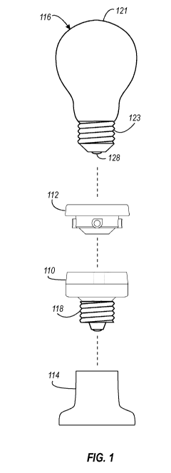
5 [10] FIG. 1 is an exploded view depicting a base adapter, a bulb adapter,
a light socket,
and a light bulb.
[11] FIG. 2 is an exploded view depicting the base adapter and bulb adapter
shown in
FIG. 1 secured to a light socket and a light bulb.
[12] FIG. 3 is a side view depicting a light bulb secured to a light socket
using the base
adapter and bulb adapter shown in FIG. 1.
[13] FIG. 4 is a top view depicting the base adapter shown in FIG. 1.
[14] FIG. 5 is a top isometric view depicting the base adapter shown in FIG.
1.
[15] FIG. 6 is a bottom isometric view depicting the base adapter 110 shown in
FIG. 1.
[16] FIG. 7 is a side view depicting the base adapter shown in FIG. 1.
[17] FIG. 8 is a top view depicting the bulb adapter shown in FIG. 1.
[18] FIG. 9 is a bottom view depicting the bulb adapter shown in FIG. 1.
CA 02993968 2017-10-26
WO 2016/176564
PCT/US2016/030072
6
[19] FIG. 10 is a top isometric view depicting the bulb adapter shown in FIG.
1.
[20] FIG. 11 is a bottom isometric view depicting the bulb adapter shown in
FIG. 1.
[21] FIG. 12 is an exploded view depicting the bulb adapter shown in FIG. 1.
[22] FIG. 13 is a partial side view depicting the bulb adapter shown in FIG.
1.
[23] FIG. 14 is an enlarged cross-sectional view depicting the bulb adapter
installed in
the base adapter shown in FIG. 1.
[24] FIGS. 15-16 depict another embodiment of a coupling mechanism, shown
being
applied to light bulbs.
[25] FIG. 15 is an exploded sectional view depicting another embodiment of a
coupling mechanism.
[26] FIG. 16 is a sectional view depicting the coupling mechanism of FIG. 15
assembled.
[27] FIG. 17 is an exploded sectional view depicting another embodiment of a
coupling mechanism.
[28] FIG. 18 is a sectional view depicting the coupling mechanism of FIG. 17
assembled.
CA 02993968 2017-10-26
WO 2016/176564 PCT/US2016/030072
7
[29] FIG. 19 is a view depicting the interior wall of the base adapter FIG. 1.
[30] FIG. 20 is a view depicting the interior wall of another embodiment of a
base
adapter.
[31] FIGS. 21-22 provide an example of a coupling mechanism used to secure two
objects together.
[32] FIG. 21 is an exploded side view depicting a coupling mechanism used to
couple
two objects.
[33] FIG. 22 is a side view depicting a coupling mechanism used to couple two
objects.
CA 02993968 2017-10-26
WO 2016/176564
PCT/US2016/030072
8
DESCRIPTION
[34] The present disclosure describes coupling mechanisms to easily and
securely
couple objects together. In some embodiments, systems are disclosed that
enable a user to
install, remove, or replace conventional light bulbs in conventional light
bulb sockets,
without the need to rotate the light bulb several revolutions, as is normally
done. While
the coupling mechanisms described may be applied to any desired application,
by way of
example, detailed examples of coupling mechanisms applied to conventional
light bulbs
will be described.
[35] Generally, the present disclosure describes a system that uses a set
of adapters to
provide an improved light bulb coupling system. In some embodiments, a first
adapter is
threaded to the male threads of a conventional light bulb and a second adapter
is threaded
to the female threads of a conventional light bulb socket. Note that the
adapters can be
configured for use with any types of bulb and socket, besides just threaded
bulbs and
sockets. For example, the adapters can be configured to be used with bulbs and
sockets
with screw bases, twist and lock bases, specialty bases, pin bases, bayonet
bases, plug-in
bases, etc. The first and second adapters are configured in such a way that
the adapters
can be quickly, easily, and securely coupled together, thus making the process
of
installing or replacing light bulbs easier. Several exemplary coupling
mechanisms are
described below, including magnetic coupling and mechanical/magnetic coupling.
Other
coupling techniques may also be used. The adapters can also be used as
adapters from
one type of bulb to another. In other words, the adapters can be configured to
CA 02993968 2017-10-26
WO 2016/176564
PCT/US2016/030072
9
accommodate a screw base bulb with a non-screw base socket. In other words, a
bulb
adapter can be configured to accommodate one type of bulb, and a base adapter
can be
configure to accommodate a different type of socket.
[36] FIGS. 1-14 are diagrams depicting a first example of first and second
adapters
used to couple a conventional light bulb to a conventional socket. FIG. 1 is
an exploded
view showing a base adapter 110, a bulb adapter 112, a conventional light
socket 114,
and a conventional light bulb 116. The light socket 114 may be any type of
socket,
including a lamp socket, light fixture socket, etc. The light bulb 116 may be
any type of
light, for example, an incandescent light, a compact fluorescent light, an LED
light, etc.
In the example shown in FIG. 1, the light bulb 116 includes a glass or plastic
bulb 121,
and threaded cap 123, and an electrical contact 128. In this example, the
threaded cap 123
is an E26 fitting. Power is provided to the light bulb 116 via the cap 123 and
the contact
128.
[37] As is described in detail below, the bulb adapter 112 has female threads
configured to receive the male threads of a light bulb. The base adapter 110
includes male
threads 118, configured to screw into the female threads of a light socket.
The base
adapter 110 and the bulb adapter 112 include a coupling mechanism that enables
the base
adapter 110 and the bulb adapter 112 to be easily and securely coupled
together. FIG. 2 is
an exploded view depicting the base adapter 110 secured to the light socket
114 and the
bulb adapter 112 secured to the light bulb 116. Once both adapters 110 and 112
are
secured to the socket 114 and bulb 116, the light bulb 116 can be easily
installed, as is
CA 02993968 2017-10-26
WO 2016/176564
PCT/US2016/030072
described in detail below. In addition to providing a mechanical coupling, the
adapters
110 and 112 provide an electrical connection between the light bulb 116 and
the socket
114 (described below). FIG. 3 is a side view of the light bulb 116 secured to
the light
socket 114 via the adapters 110 and 112.
5 [38] FIGS. 4-7 depict details of one embodiment of a base adapter 110.
FIG. 4 is a top
view of the base adapter 110 shown in FIG. 1. FIG. 5 is a top isometric view
of the base
adapter 110 shown in FIG. 1. FIG. 6 is a bottom isometric view of the base
adapter 110
shown in FIG. 1. FIG. 7 is a side view of the base adapter 110 shown in FIG. 1
using
hidden lines to show various details of the base adapter 110. FIG. 1 also
includes a side
10 view of the base adapter 110.
[39] As mentioned above, in the embodiment shown, the socket adapter 110 has
standard male threads 118 configured to thread into a conventional light
socket, such as
socket 114 shown in FIGS. 1 and 2. In one example, threads 118 comply with the
Edison
Screw (ES) E526 standard. A cavity 119 is formed in the opposite end of the
base adapter
110. The cavity 119 is configured to receive and secure the bulb adapter 112.
The
electrical connections needed to power the light bulb 116 are provided in the
cavity 119,
and are described in detail below with respect to FIG. 14. The base adapter
110 includes a
center contact assembly that includes a center contact alligator 122 (FIGS. 4,
14) that is
configured to make contact with the contact 128 of the light bulb. The
alligator 122 is in
electrical contact with male and female center contact pins 124 and 126,
respectively
(FIG. 14). During use, the female contact pin 126 makes electrical contact
with the center
CA 02993968 2017-10-26
WO 2016/176564
PCT/US2016/030072
11
conductor (not shown) of a light socket, thus providing an electrical
connection between
the light bulb contact 128 and the center conductor of the light socket.
[40] Within the cavity 119 of the base adapter 110 four downward sloping
channels
132 are formed, and each terminate below a retention surface 134 at a
termination point
136. FIGS. 19-20 (described below) show the channels 32, termination points
136, and
retention surfaces 134 in more detail. As described below, the bulb adapter
112 includes
four corresponding protrusions 142 (described below). When the adapter
assembly is in
use, the protrusions 142 will be guided below the retention surface 134 by the
sloping
channels 132. When the bulb adapter 112 is inserted into the base adapter 110,
the
channels 132 will guide each of the protrusions 142 of the bulb adapter 112
toward the
respective termination point 136 as the base adapter 110 is rotated slightly
(in this
example, approximately 1/8 of a turn).
[41] In the proximity of each of the termination points 136, a magnet 120 (or
other
magnetic material or magnetic receptive material) is formed in the wall of the
base
adapter 110. This is illustrated best in FIGS. 5, 14, and 19. When the bulb
adapter 112 is
inserted in the base adapter 110 with the protrusions 142 at or near the
termination points
136, the bulb adapter 112 will be held securely in place by the magnets
120/144 and the
retention surface 134. To remove a bulb, a user simply rotates the bulb
counterclockwise
(approximately 1/8 of a turn) until the protrusions 142 of the bulb adapter
112 are no
longer beneath the retention surfaces 134.
CA 02993968 2017-10-26
WO 2016/176564
PCT/US2016/030072
12
[42] FIGS. 8-13 depict details of one embodiment of a bulb adapter 112. FIG. 8
is a
top view of the bulb adapter 112 shown in FIG. 1. FIG. 9 is a bottom view of
the bulb
adapter 112 shown in FIG. 1. FIG. 10 is a top isometric view of the bulb
adapter 112
shown in FIG. 1. FIG. 11 is a bottom isometric view of the bulb adapter 112
shown in
FIG. 1. FIG. 1 includes a side view of the bulb adapter 112. FIG. 12 is an
exploded view
of the bulb adapter 112 shown in FIG. 1, showing a bayonet portion 138 and a
screw
shell 140. FIG. 13 is a side view of the bayonet portion 138 with hidden lines
showing
various features of the bayonet portion 138.
[43] As shown in the figures, four protrusions 142 are formed near the bottom
of the
bulb adapter 112, extending radially from the bulb adapter 112. The
protrusions 142 of
the bulb adapter 112, in combination with the channels 132 of the base adapter
110, form
a coupling mechanism similar to a bayonet-style coupling. A magnet 144 (or
other
magnetic material or magnetic receptive material) is disposed at each
protrusion 142 to
attract the corresponding magnet 120 of the base adapter 110. In one
embodiment,
magnets are used on both the bulb adapter 112 and base adapter 110. In other
embodiments, a magnet in one adapter (the bulb adapter 112 or base adapter
110)
corresponds to a magnetic receptive material in the other adapter, as desired.
Using a
magnet in combination with a magnetic receptive material (e.g., iron, other
ferromagnetic
materials, etc.) may reduce the cost of an adapter assembly, at the expense of
a reduced
magnetic attraction. In the examples shown, four protrusions 142 and
corresponding
channels 132 are used. In other examples, more or less protrusions/channels
may be used
(e.g., 1, 2, 3, 5, etc.), as desired.
CA 02993968 2017-10-26
WO 2016/176564
PCT/US2016/030072
13
[44] As shown best in FIGS. 12 and 14, the screw shell 140 is disposed within
the bulb
adapter 112, and forms female threads for receiving a light bulb. The screw
shell also
provides an electrical connection between the threads of the cap 123 of the
light bulb 116
and the base adapter 110 (described below). The screw shell 140 includes a
bottom lip
146 that engages the bottom of the light bulb 116 (FIG. 2), and provides a
stopping
surface when screwing the light bulb 116 into the bulb adapter 112. The upper
portion of
the bulb adapter 112 forms a lip 148 (FIGS. 13, 14), which overlaps the base
adapter 110
during use (FIGS. 3, 14), providing protection from rain, dirt, or other
elements.
[45] FIG. 14 is an enlarged cross-sectional view of the bulb adapter 112
installed in the
base adapter 110. For clarity, a light bulb and a light socket are not shown.
As shown,
and as described above, the protrusions 142 of the bulb adapter 112 are
disposed within
the channels 132 of the base adapter 110 and below the retentions surfaces
134. As
shown, the magnets 120 and 144 are relatively close each other, resulting in a
strong
attraction. The attraction of the magnets 120 and 144, along with the
protrusions 142
being disposed within the channels 132 and below the retention surfaces 134,
work
tougher to hold the adapters 112 and 110 together.
[46] As described above, the bulb adapter 112 and base adapter 110 provide the
necessary electrical connections between a light bulb 116 and a light socket
114. The
light bulb 116 requires a connection to the threaded cap 123 and the bulb
contact 128.
During use, the threaded cap 123 of the light bulb 116 engages and makes
electrical
contact with the screw shell 140 of the bulb adapter 112. When the bulb
adapter 112 is
CA 02993968 2017-10-26
WO 2016/176564
PCT/US2016/030072
14
secured to the base adapter 110, the screw shell 140 makes electrical contact
with a
contact ring 150 (FIGS. 4, 5, 14). The contact ring 150 includes a downward
extending
tab 152 (FIG. 14). The tab 152 makes electrical contact with the threads 118
of the base
adapter 110 (FIG. 14), which makes electrical contact with the female threads
of the light
socket 114 (not shown), thus providing an electrical connection between the
threaded cap
123 of the light bulb 116 with the female threads of the light socket 114.
During use, the
bulb contact 128 of the light bulb 116 makes electrical contact with the
alligator 122 of
the base adapter 110, which makes electrical contact with the pin 126 (FIG.
14), which
makes contact with the center conductor of the light socket 114 (not shown),
thus
providing an electrical connection between the contact 128 of the light bulb
116 with the
center contact of the light socket 114.
[47] The adapter assembly shown in FIGS. 1-14 operates as follows. To install
a light
bulb using the embodiment illustrated in FIGS. 1-14, a base adapter 110 is
screwed into
the socket 114 of a light fixture (FIG. 2). A bulb adapter 112 is screwed onto
the light
bulb 116 to be installed (FIG. 2). With both adapters 110 and 112 installed, a
user can
merely insert the bulb 116 (along with the bulb adapter 112) into the cavity
of the base
adapter 110 until the base adapter 110 magnets 120 engage the bulb adapter
magnets 144
as the protrusions 142 are guided through the channels 132. The engagement of
the pairs
of magnets pull the bulb to the installed position, providing tactile feedback
(e.g., a snap
or click that can be felt and/or heard) to the user, so the user can be sure
that the light
bulb is properly secured. The retention surfaces 134 prevent the bulb 116 from
being
pulled straight out. To remove the light bulb 116, a user will twist the bulb
116 slightly
CA 02993968 2017-10-26
WO 2016/176564
PCT/US2016/030072
with sufficient force to overcome the magnetic force of the magnets holding
the adapter
assembly together. When replacing a bulb, the base adapter 110 can remain in
place, and
a new bulb installed using the same (or another) bulb adapter 112.
[48] Note that the magnets used in the various embodiments described can be
5 comprised of any desired type of magnetic material, for example,
Neodymium, ferrite
ceramic, etc. Also note that, when the description describes magnets and/or
corresponding ferromagnetic materials, magnetic receptive materials, etc., the
materials
can be reversed. Where a magnetic coupling is used, the coupling can be
accomplished
using a magnet paired with another magnet, or by a magnet and a ferromagnetic
material
10 or magnetic receptive material.
[49] In another example, a coupling mechanism, such as those described herein,
can be
incorporated in a light bulb and/or socket, so no adapters are needed. For
example, a light
bulb can be manufactured with the functionalities of the bulb adapter built
in. Such a bulb
may look like the combination of bulb 116 and adapter 112 shown in FIG. 2. A
matching
15 socket may look like the combination of socket 114 and adapter 110 shown
in FIG. 2. In
another example, bulb can be manufactured to incorporate the adapter 112
functionalities,
and then used in conventional sockets with an adapter such as base adapter
110.
[50] FIGS. 15-16 depict another embodiment of a coupling mechanism, shown
being
applied to light bulbs. FIG. 15 is an exploded sectional view depicting a base
adapter 210
and a bulb adapter 212. FIG. 16 shows the base adapter 210 and bulb adapter
212
CA 02993968 2017-10-26
WO 2016/176564
PCT/US2016/030072
16
attached. For clarity, a light bulb and light socket are not shown. The bulb
adapter 212
has female threads 240 configured to receive the threads of a light bulb. The
base adapter
210 has male threads 218 configured to thread into a light socket. The bulb
adapter 212
and base adapter 210 are configured to couple together in a manner that allows
a user to
quickly and easily install and remove a light bulb.
[51] A cavity 219 is formed in the top end of the base adapter 210. The cavity
219 is
configured to receive the bulb adapter 212. The electrical connections needed
to power
the light bulb are provided in the cavity 119, as shown, or in a manner
similar to that
illustrated in FIG. 14. To secure a light bulb and bulb adapter 212 within the
cavity 219, a
pair of magnets 220 is formed in the wall of base adapter 210. In the example
shown, two
magnets 220 are positioned on the opposite sides of the base adapter 210. In
other
examples, more or less magnets may be used. In this example, a magnetic ring
244 (or
alternatively, a magnetic receptive ring) is disposed near the bottom of the
bulb adapter
212. The magnetic ring 244 will hold the light bulb in place, due to magnetic
attraction
between the magnets 220 of the base adapter 210 and the magnetic ring 244.
When the
bulb adapter 212 is threaded onto a light bulb, the light bulb and adapter 212
can be
inserted into the base adapter 210 without a user being required to rotate the
light bulb.
When the light bulb and adapter 212 are inserted far enough, the magnetic
attraction
between the magnets 220 and the magnetic ring 244 will hold the light bulb in
place.
[52] FIGS. 17-18 depict another embodiment of a coupling mechanism having a
secondary securing means, shown being applied to light bulbs. FIG. 17 is an
exploded
CA 02993968 2017-10-26
WO 2016/176564
PCT/US2016/030072
17
sectional view depicting a base adapter 310 and a bulb adapter 312. FIG. 18
shows the
base adapter 310 and bulb adapter 312 attached. For clarity, a light bulb and
light socket
are not shown. Other than the secondary securing means (described below), the
adapters
310 and 312 can be the same, or similar to the adapters 210 and 212 shown in
FIGS. 15-16.
[53] Referring to FIG. 17, the base adapter 310 includes threads 318,
configured to
thread into a light socket. Magnets 320 are formed in the wall of the adapter
310. In the
example shown in FIGS. 17-18, a secondary securing means is provided by a pair
of
spring ball plungers and corresponding grooves. In other examples, more or
less than two
secondary securing means may be used. Each ball spring plunger includes a ball
340,
which is biased toward the cavity of the adapter 310 by spring 342. A
corresponding
groove(s) 343 is formed the bulb adapter 312. When the bulb adapter 312 is
inserted into
the base adapter 310 (FIG. 18), the spring balls 340 will help hold the bulb
adapter 312 in
place by engaging the grooves 343. As shown in FIG. 18, in this position, the
adapter 312
is secured in place by both the secondary securing means and the magnetic
coupling.
[54] To install a light bulb using either of the embodiments illustrated in
FIGS. 15-18,
a base adapter 210/310 is screwed into the socket of a light fixture. A bulb
adapter
212/312 is screwed onto the bulb to be installed. With both adapters
installed, a user has
to merely insert the bulb (along with the bulb adapter 212/312) into the
cavity of the base
adapter 210/310 until the bulb adapter 212/312 magnets 220/320 engage the
magnetic
ring 244/344, which will hold the bulb in place. In the embodiment shown in
FIGS. 17-
CA 02993968 2017-10-26
WO 2016/176564
PCT/US2016/030072
18
18, the secondary securing means will also assist in holding the bulb in
place. To remove
the bulb, a user will pull on the bulb with sufficient force to overcome the
magnetic force
holding the bulb and socket together (and the force of the secondary securing
means, if
used).
[55] FIG. 19 is an "unwrapped" view of the interior wall of the base adapter
110
shown in FIGS. 4-7, showing the channels 132 in more detail. As shown, four
downward
sloping channels 132 are formed, extending downward and terminating at
termination
points 136. Magnets 120 are disposed proximate the termination points 136. An
upper
surface of the each channel 132 is provided by retention surface 134. When the
bulb
adapter 112 is fully inserted in the base adapter 110 (with the protrusions
142 proximate
the termination points 136, the magnets 120/144 will hold the adapters in
position. The
retention surface 134 will also prevent the bulb adapter 112 from pulling out,
unless
sufficient rotational force is applied to disengage the magnets 120/144.
[56] FIG. 20 is an unwrapped view of the interior wall of another embodiment
of a
base adapter, with a secondary securing means. FIG. 20 is the same as FIG. 19,
but
includes a secondary securing means for applications where a more secure
connection is
desired. In this example, a perpendicular channel (or "serif") 154 is formed
near the
termination points 136. When the protrusions 142 of the bulb adapter 112 are
disposed
within the serifs 154, additional rotational resistance is provided,
preventing the bulb
from being rotated, without pushing in on the bulb, to move the protrusions
142 out of the
CA 02993968 2017-10-26
WO 2016/176564
PCT/US2016/030072
19
serifs 154. To remove a bulb in this example, a user simply presses inwards
slightly while
turning the bulb counterclockwise.
[57] The coupling mechanisms described above were described in the context of
light
bulbs and light sockets, as examples only. The coupling mechanisms described
can be
applied to any other desired applications. FIGS. 21-22 provide an example of a
coupling
mechanism used to secure two objects together. In the examples shown, a
coupling
mechanism similar to that shown in FIGS. 1-14 is used.
[58] FIG. 21 is an exploded side view of a first coupling member 410 coupled
to a first
object 411 and a second coupling member 412 coupled to a second object 413.
FIG. 22 is
a side view of the first object 411 coupled to the second object 413 via first
and second
coupling members 410 and 412. The first member 410 and second member 412 are
similar to the base adapter 110 and bulb adapter 112 shown in FIGS. 1-14, but
without
the light bulb/socket threads, electrical contacts, etc. As before, the first
member 410
includes channels, magnets, etc. (not shown) like those shown in FIGS. 4-7 and
the
second member 412 includes protrusions 442 and magnets 444 like those shown in
FIGS.
8-11. The objects 411 and 413 can be any desired objects, walls, surfaces,
tools,
interchangeable accessories, doors/latches, etc., as desired. To secure the
second object
413 to the first object 411, a user simply inserts and slightly rotates the
second member
412 into the first member 410, in the same manner as described above with
respect to the
adapters shown in FIGS. 1-14.
CA 02993968 2017-10-26
WO 2016/176564 PCT/US2016/030072
[59] In the preceding description, the disclosure is described with reference
to specific
exemplary embodiments thereof. Various modifications and changes may be made
thereto without departing from the broader spirit and scope of the disclosure.
The
specification and drawings are, accordingly, to be regarded in an illustrative
rather than a
5 restrictive sense.