Note: Descriptions are shown in the official language in which they were submitted.
CA 02994059 2018-01-29
- 1 -
DESCRIPTION
CONTROL DEVICE FOR ELECTRIC VEHICLE AND CONTROL METHOD
FOR ELECTRIC VEHICLE
TECHNICAL FIELD
[0001] The present invention relates to a control device for an electric
vehicle and a control method for the electric vehicle.
BACKGROUND ART
[0002] Braking force used when an electric vehicle is decelerated or
stopped
is obtained from regenerative braking by a motor and friction braking by a
brake. The regenerative braking has a better controllability of the braking
force than that of the friction braking. Thus, to smoothly stop the electric
vehicle, it is preferable to stop the vehicle by the regenerative braking, not
by
the friction braking. Especially, in a vehicle that performs driving and
braking of the motor according to an opening degree of an accelerator pedal,
it
is necessary to stop the vehicle by adjusting the braking force according to
disturbance. Thus, it is preferable to perform the regenerative braking having
good controllability just before stop of the vehicle.
[0003] However, conventionally, if the regenerative braking is performed
when a battery is in a full charge state, the battery is possibly excessively
charged. Thus, when the battery is in the full charge state, the electric
vehicle
is stopped by the friction braking, not the regenerative braking
(JP2012-29461A).
SUMMARY OF INVENTION
[0004] Insofar as the battery is in the full charge state, if the
regenerative
braking is performed, the battery is excessively charged. Thus, the friction
- 2 -
braking has to be performed. Therefore, there is a problem that the electric
vehicle cannot be smoothly stopped.
[0005] It
is an object of the present invention to provide a technique that
solves a problem that an electric vehicle cannot be smoothly stopped when a
battery is in a full charge state.
[0006]
According to one embodiment of the present invention, a control
device for an electric vehicle that generates a braking force corresponding to
an opening degree of an accelerator pedal to decelerate the electric vehicle.
The control device for the electric vehicle comprising: a motor configured to
generate a driving force or a regenerative braking force of the electric
vehicle;
a friction braking unit configured to generate a friction braking force; and a
controller configured to control at least one of the motor and the friction
braking unit corresponding to the opening degree of the accelerator pedal.
The controller determines whether all of regenerative electric power generated
by the motor is consumed in the electric vehicle when the braking force is
generated by the motor alone, and generates the regenerative braking force
by the motor when the controller detei ____________________________________
mines that all of the regenerative
electric power is consumed in the electric vehicle.
According to an aspect of the present invention there is provided a
control device for an electric vehicle that generates a braking force when an
accelerator pedal is not depressed to decelerate the electric vehicle,
the control device for the electric vehicle comprising:
a motor configured to generate a driving force or a regenerative braking
force of the electric vehicle,
Date Recue/Date Received 2021-10-15
-2a-
a friction braking unit configured to generate a friction braking force,
a battery charged by the regenerative electric power from the motor, and
a controller configured to control at least one of the motor and the
friction braking unit corresponding to the opening degree of the accelerator
pedal,
wherein:
the controller determines whether the battery can be charged or not
based on an available capacity of the battery,
the controller generates the braking force by the motor when the
controller determines that the battery can be charged based on an available
capacity of the battery,
the controller determines if a charging current that flows toward the
battery is positive or negative based on the motor torque command value and
the motor rotation speed when the controller determines that the battery
cannot be charged based on the available capacity of the battery, and the
charging current is positive when the regenerative electric power by the motor
exceeds the power consumption of the electric vehicle and the battery is
charged, and the charging current is negative when the regenerative electric
power by the motor falls below the power consumption of the electric vehicle
and the battery is discharged, and
the controller generates the regenerative braking force by the motor
when the controller determines that the charging current is negative, and
the controller controls, before a start of a stop control that generates
the regenerative braking force by the motor to stop the electric vehicle, the
generation of the regenerative braking force by the motor such that the
Date Recue/Date Received 2021-10-15
-2h-
available capacity of the battery becomes equal to or more than a specified
charging electric energy charged to the battery from the start of the stop
control to a timing at which the regenerative electric power becomes equal to
a power consumption consumed in the electric vehicle.
According to another aspect of the present invention there is provided
a control method for an electric vehicle that includes a motor, a friction
braking unit and a battery, the motor being configured to generate a driving
force or a regenerative braking force of the electric vehicle when an
accelerator pedal is not depressed, the friction braking unit being configured
to generate a friction braking force, the battery charged by the regenerative
electric power from the motor, the control method for the electric vehicle
generating a braking force corresponding to the opening degree of the
accelerator pedal to decelerate the electric vehicle,
the control method for the electric vehicle comprising:
a first determining step of determining whether the battery can be
charged or not based on an available capacity of the battery,
a generating step of generating the braking force by the motor alone
when the battery is determined to be charged based on an available capacity
of the battery,
by a second determining step of determining if the charging current
that flows toward the battery is positive or negative based on the motor
torque
command value and the motor rotation speed when it is determined in the
first determining step that the battery cannot be charged based on the
available capacity of the battery, and the charging current is positive when
Date Recue/Date Received 2021-10-15
-2c-
the regenerative electric power by the motor exceeds the power consumption
of the electric vehicle and the battery is charged, and the charging current
is
negative when the regenerative electric power by the motor falls below the
power consumption of the electric vehicle and the battery is discharged, and
a controlling step of controlling the motor to perform the regenerative
braking when it is determined in the second determining step that the
charging current is negative and
wherein the controlling step is performed, before a start of a stop
control that generates the regenerative braking force by the motor to stop the
electric vehicle, the generation of the regenerative braking force by the
motor
such that the available capacity of the battery becomes equal to or more than
a specified charging electric energy charged to the battery from the start of
the stop control to a timing at which the regenerative electric power becomes
equal to a power consumption consumed in the electric vehicle.
BRIEF DESCRIPTION OF DRAWINGS
[0007]
FIG. 1 is a schematic configuration diagram of an electric vehicle
including a motor controller of a first embodiment.
FIG. 2A is a view illustrating a vehicle model.
FIG. 2B is a view illustrating a vehicle model.
FIG. 3 is a flowchart illustrating running control of the electric vehicle.
FIG. 4 is a view illustrating an exemplary torque table.
FIG. 5 is a block diagram illustrating a stop control process.
FIG. 6 is a block diagram illustrating a process in a motor rotation
speed
Date Recue/Date Received 2021-10-15
CA 02994059 2018-01-29
1
- 3 -
F/B torque setting block.
FIG. 7 is a block diagram illustrating a process in a disturbance torque
estimating block.
FIG. 8 is a flowchart illustrating a command value calculation control.
FIG. 9 is a view illustrating an exemplary charging current table.
FIG. 10 is a block diagram illustrating a filter process.
FIG. 11 is timing charts illustrating exemplary running conditions of the
electric vehicle.
FIG. 12 is charging current tables illustrating operations of the electric
vehicle in the timing charts in FIG. 11.
FIG. 13 is timing charts illustrating other exemplary running conditions
of the electric vehicle.
FIG. 14 is charging current tables illustrating operations of the electric
vehicle in the timing charts in FIG. 13.
FIG. 15 is a schematic configuration diagram of an electric vehicle
including a motor controller of a second embodiment.
FIG. 16 is a block diagram illustrating a stop control process.
FIG. 17 is a flowchart illustrating a command value calculation control.
FIG. 18 is a charging current table illustrating an operation of the electric
vehicle.
FIG. 19 is a flowchart illustrating a command value calculation control
performed by a motor controller of a third embodiment.
FIG. 20 is a charging current table illustrating an operation of the electric
vehicle.
DESCRIPTION OF EMBODIMENTS
[0008] The
following describes embodiments of the present invention with
reference to the drawings.
CA 02994059 2018-01-29
- 4 -
[0009] (First Embodiment)
FIG. 1 is a schematic configuration diagram of an electric vehicle 100 that
includes a motor controller 14 as a control device according to the first
embodiment.
[0010] The electric vehicle 100 includes a motor 1 as a part of or the
entire
driving source. In this embodiment, it is assumed that the motor 1 mounted
to the electric vehicle 100 operates in three-phases (U, V, and W phases). It
should be noted that the electric vehicle 100 may be an electric vehicle that
uses an electric motor as a driving source and a hybrid vehicle that uses an
electric motor and an engine as driving sources.
[0011] The electric vehicle 100 according to the embodiment can perform
acceleration and deceleration and stop only by operating an accelerator pedal.
That is, a driving torque and a regenerative torque generated by the motor 1
are determined according to an opening degree of the accelerator pedal.
Therefore, an increase in the opening degree of the accelerator pedal
increases
the driving torque generated by the motor 1, accelerating the electric vehicle
100. Additionally, the reduction in the opening degree of the accelerator
pedal reduces the driving torque generated by the motor 1 or increases a
regenerative braking force by the motor 1 and a friction braking force by a
friction braking unit 7, decelerating or stopping the electric vehicle 100. It
should be noted that although the electric vehicle 100 may include a brake
pedal, the brake pedal is used in the case where a braking force larger than a
braking force generated when the opening degree of the accelerator pedal
becomes zero is required.
[0012] The electric vehicle 100 includes the motor 1, a battery 2, an
inverter 3, a reduction gear 4, a shaft 5, driving wheels 6, the friction
braking
unit 7, a voltage sensor 8, a current sensor 9, a rotation sensor 10, a fluid
pressure sensor 11, a friction brake controller 12, a battery controller 13,
and
CA 02994059 2018-01-29
- 5 -
the motor controller 14.
[0013] The motor 1 includes a rotator that operates by three-phase electric
powers (U, V, and W phases). In the motor 1, flowing three-phase alternating
currents iu, iv, and iw from the battery 2 through the inverter 3 generates a
torque according to the alternating currents iu, iv, and iw. The torque
generated in the motor 1 is transmitted to the driving wheels 6 via the
reduction gear 4 and the shaft 5. The motor 1 performs regenerative braking
to decelerate or stop the electric vehicle 100. The regenerative braking by
the
motor 1 generates regenerative electric power, and the battery 2 is charged by
the regenerative electric power. It should be noted that the regenerative
electric power generated by the motor 1 is an AC power.
[0014] The battery 2 is a batter that can be charged and discharged, such
as a lithium battery. A DC electric power supplied from the battery 2 is
converted into the AC power by the inverter 3, and this AC power is supplied
to
the motor 1. The battery 2 is charged not only at a charging station but also
is
charged by the regenerative electric power generated in the motor 1 while the
electric vehicle 100 decelerates. The voltage sensor 8 is disposed between the
battery 2 and the inverter 3.
[0015] The inverter 3 converts a direct current output from the battery 2
into the three alternating currents iu, iv, and iw according to a duty ratio
(%) of
PWM signals Tu, Tv, and Tw output from the motor controller 14. The
inverter 3 supplies the convert alternating currents iu, iv, and iw to the
motor
1. It should be noted that in the case where the motor 1 generates the
regenerative electric power and outputs the alternating current, the inverter
3
converts the alternating current into the direct current and outputs the
converted direct current to the battery 2. The current sensor 9 is disposed
between the inverter 3 and the motor 1.
[0016] The inverter 3, for example, includes two pieces of switching
CA 02994059 2018-01-29
- 6 -
elements (not illustrated), which are provided corresponding to each of the U,
V,
and W phases. In the inverter 3, according to the duty ratio of the PWM
signals Tu, Tv, and Tw, on and off of the switching elements are switched.
The direct current supplied from the battery 2 by the switching of the
switching elements is converted into the desired alternating currents iu, iv,
and iw, and the alternating currents iu, iv, and iw are supplied to the motor
1.
[0017] It should
be noted that as the switching elements, there have been
provided a power semiconductor device such as an Insulated Gate Bipolar
Transistor (IGBT) and a Metal-Oxide-Semiconductor Field-Effect Transistor
(MOS-FET).
[0018] The
reduction gear 4 converts the torque generated in the motor 1
and transmits the converted torque to the shaft 5. A ratio that a rotation
speed of the motor 1 is converted into a rotation speed of the shaft 5 is
referred
to as a final gear ratio. That is, the reduction gear 4 converts the rotation
speed of the motor 1 into the rotation speed of the shaft 5 according to the
final
gear ratio.
[0019] The shaft 5
is rotated by the torque transmitted from the motor 1 via
the reduction gear 4.
[0020] The driving
wheels 6 are mounted to both ends of the shaft 5 and
rotate in accordance with the rotation of the shaft 5. Thus, the rotation of
the
driving wheels 6 causes the electric vehicle 100 to run.
[0021] The
friction braking unit 7 is a friction braking and is disposed
adjacent to the driving wheel 6. The friction braking unit 7 and the friction
brake controller 12 are, for example, coupled via an oil passage using oil.
The
friction braking unit 7 generates the friction braking force according to a
fluid
pressure of the oil passage between the friction braking unit 7 and the
friction
brake controller 12.
[0022] The current
sensor 9 measures the three-phase alternating currents
CA 02994059 2018-01-29
1
- 7 -
iu, iv, and iw supplied from the inverter 3 to the motor 1. The current sensor
9 outputs the measured three-phase alternating currents iu, iv, and iw to the
motor controller 14.
[0023] The
rotation sensor 10 is, for example, a resolver and an encoder
that detects a rotator phase a (rad), a phase of the rotator of the motor 1.
The
rotation sensor 10 outputs the detected rotator phase a to the motor
controller
14.
[0024] The
fluid pressure sensor 11 measures the fluid pressure of the
friction braking unit 7.
[0025] The
friction brake controller 12 obtains a fluid pressure command
value from an input of a friction torque command value Tb* from the motor
controller 14 to and a brake fluid pressure from the fluid pressure sensor 11.
The friction brake controller 12 controls the fluid pressure of the oil
passage
between the friction braking unit 7 and the friction brake controller 12
according to the obthined fluid pressure command value.
[0026] The
battery controller 13 monitors the state of the battery 2 to
obtain a State Of Charge (SOC) (%) indicative of a remaining amount of the
battery 2. The battery controller 13 obtains a regenerable electric power Pin
(W) from the SOC of the battery 2 and the temperature. The battery controller
13 outputs the obtained regenerable electric power Pin to the motor controller
14. It
should be noted that the regenerable electric power Pin becomes zero or
a positive value. It should be noted that, instead of the SOC, a Depth Of
Discharge (DOD) indicative of a ratio of the discharge relative to the
capacity
may be used.
[0027] To
the motor controller 14, a vehicle speed V of the electric vehicle
100 from a vehicle speed sensor (not illustrated), an accelerator position
(accelerator opening degree) 0 from an accelerator position sensor (not
illustrated), which measures a depression amount of the accelerator pedal, a
CA 02994059 2018-01-29
- 8 -
direct-current voltage value Vdc from the voltage sensor 8, the three-phase
alternating currents iu, iv, and iw from the current sensor 9, the rotator
phase
a of the motor 1 from the rotation sensor 10, the brake fluid pressure from
the
fluid pressure sensor 11, and the SOC and the regenerable electric power Pin
from the battery controller 13 are input. The motor controller 14 outputs the
PWM signals Tu, Tv, and Tw to the inverter 3 via a drive circuit on the basis
of
these inputs and outputs the friction torque command value Tb* to the friction
brake controller 12. Detailed operations of the motor controller 14 will be
described later. It should be noted that, taking the regenerative braking by
the motor 1 and responsiveness of the friction braking by the friction braking
unit 7 into consideration, the motor controller 14 controls the torque
command value.
[0028] The following describes transfer functions in a vehicle model in
which a drive transmission system of the electric vehicle 100 used in
processes
by the motor controller 14 is modeled. The transfer functions Gp(s), Gb(s),
Gpa(s), and Gba(s) are used for the processes by the motor controller 14.
[0029] The transfer function Gp(s) indicates transfer characteristics from
an input of a motor torque Tm generated by the motor 1 to an output of a
motor rotation speed Cm as the rotation speed of the motor 1.
[0030] The transfer function Gb(s) indicates transfer characteristics from
an input of a friction torque Tb generated in the friction braking unit 7 to
an
output of the motor rotation speed G.)m.
[0031] The transfer function Gpa(s) indicates transfer characteristics from
the input of the motor torque Tm to an output of an acceleration a of the
electric vehicle 100.
[0032] The transfer function Gba(s) indicates transfer characteristics from
the input of the friction torque Tb to the output of the acceleration a of the
electric vehicle 100.
CA 02994059 2018-01-29
=
- 9 -
[0033] The following describes these transfer functions with
reference to
FIG. 2A and FIG. 2B.
[0034] FIG. 2A and FIG. 2B are views illustrating the vehicle
model in
which a drive force transmission system of the electric vehicle 100 is
modeled.
Respective parameters in these views are as follows.
Jm: inertia of the motor 1
Jw: inertia of the driving wheels 6
M: weight of the electric vehicle 100
KD: torsional rigidity of the drive system
Kt: friction coefficient between tires and a road surface
N: overall gear ratio
r. dynamic radius of tires
corn: motor rotation speed of the motor 1
Tm: motor torque
TD: torque of the driving wheels 6
F: force applied to the electric vehicle 100
V: speed of the electric vehicle 100
ow: angular velocity of the driving wheels 6
Tb: friction braking amount generated in the friction braking unit 7 (motor
shaft conversion torque)
It should be noted that the following equations of motion of Equations (1)
to (5) can be derived from FIG. 2A and FIG. 2B. The parameters with the
asterisks (*) attached to the right upper in the following Equations (1) to
(3)
indicate that the parameters have time-differentiated values.
[0035] [Equation 1]
= co: =Tm ¨ TD I N (1)
CA 02994059 2018-01-29
- 10 -
[0036] [Equation 2]
2Jw = =TD ¨ rF ¨ N = Tb == - ( 2 )
[0037] [Equation 3]
M V* = F === (3)
[0038] [Equation 4]
TD = KD = Noõ, / N ¨ co,,,)dt ( 4 )
[0039] [Equation 5]
F = Kt(r = cow ¨V) ( 5)
[0040] Here, with the angular velocity cow of the driving wheels 6 larger
than
zero (cow > 0), that is, while the electric vehicle 100 moves forward, a
friction
braking amount Tb becomes positive (Tb > 0). With the angular velocity ov, of
the driving wheels 6 smaller than zero (caw < 0), that is, while the electric
vehicle
100 goes in reverse, the friction braking amount Tb becomes negative (Tb < 0).
With the angular velocity ow of the driving wheels 6 of zero (cow = 0) that
is,
while the electric vehicle 100 stops, the friction braking amount Tb becomes
zero (Tb = 0).
[0041] From the equations of motion of Equations (1) to (5), the transfer
function Gp(s) is obtained as Equation (6). The transfer function Gb(s) is
obtained as Equation (7).
[0042] [Equation 6]
CA 02994059 2018-01-29
- 11 -
G (s)= ks3-1-b2s2+b1s+b0
=== (6)
s(a4s3 a3s2 (22S + al)
[0043] [Equation 7]
b1s + b0
(7)
s(a4s 3 + a3s2 + a2s + al)
[0044] Note that, the respective parameters in Equations (6) and (7) are
expressed as follows.
[0045] [Equation 8]
a4 = 2Jm = Jw = M
a3 = Jm(2Jw+ Mr2)Kt
a2 = (Jm + 2Jw I N2)M = KD
al = (Jm+2Jw I N2 + Mr2 I N2)KD = Kt
b3 = 2Jw=M
b2 = (2Jw+Mr2)Kt
b,=M-KD
= KD- Kt
[0046] Through examinations, the poles and 0 paints of the transfer
function shown in Equation (6) can be approximated to a transfer function of
the following Equation (8), and one pole and one 0 points indicate values
extremely close to each other. This is equivalent to that a and r3 of Equation
(8) indicate values extremely close to each other.
[0047] [Equation 9]
+ fiXb2' S2 +b,s+b01)
G (s)= === (8)
s(s + a)(a3t s 2 + a2' s +
CA 02994059 2018-01-29
- 12 -
[0048] Therefore, by perfoiming pole-zero cancellation (approximation to a
= 13) in Equation (8), the transfer characteristics Gp(s) of (second
order)/(third
order) as shown in the following Equation (9) is constituted.
[0049] [Equation 10]
1s2 .. b ' s + bo')
G p(s) = 2 (9)
s + a2' s +
[0050] .. From the equations of motion of Equations (1) to (5), the transfer
function Gpa(s) is obtained as Equation (10) and the transfer function Gba(s)
is
obtained as Equation (11).
[0051] [Equation 11]
a
G pa(s) = bO (10)
a4S3 +a3S2 +a2 s+a
[0052] [Equation 12]
(b2aS2 + boa)
Gba(S)= = = = (1 1)
a4s3 a3s2 + a2s +
[0053] Note that, the respective parameters in Equations (10) and (11) are
expressed by the following equation.
[0054] [Equation 13]
b2a =JmrKtN
boa = r I N KD Kt
[0055] Thus, the transfer functions Gp(s), Gb(s), Gpa(s), and Gba(s) can be
obtained.
[0056] The following describes the control by the motor controller 14.
[0057] FIG. 3 is a flowchart illustrating running control of the electric
CA 02994059 2018-01-29
- 13 -
vehicle 100 by the motor controller 14. This running control is repeatedly
performed at a predetermined timing.
[0058] At S301, an input processing to the motor controller 14 is performed.
As illustrated in FIG. 1, to the motor controller 14, the direct-current
voltage
value Vdc (V), the regenerable electric power Pin (W), the friction braking
amount Tb, the vehicle speed V (m/s), the accelerator position 0 (%), the
rotator phase a (rad), and the three-phase alternating currents iu, iv, and iw
(A) are input.
[0059] The direct-current voltage value Vdc is input from the voltage
sensor
8 to the motor controller 14.
[0060] The regenerable electric power Pin is input from the battery
controller 13 to the motor controller 14. This regenerable electric power Pin
having a value other than 0 indicates that the battery 2 has an available
capacity. The regenerable electric power Pin becomes larger as the available
capacity increases.
[0061] The rotator phase a is input from the rotation sensor 10 to the
motor
controller 14.
[0062] The accelerator position 0 is input via communicating means from
the accelerator position sensor or another controller. In this embodiment, it
is assumed that the accelerator position 0 is a value in increments of 1 / 4
(25%).
That is, the accelerator position 0 is expressed by five levels 0/4 (0%), 1/4
(25%), 2/4 (50%), 3/4 (75%), and 4/4 (100%). With the accelerator position 0
of 0/4 (0%), the accelerator pedal is fully closed, that is, the accelerator
pedal
is not depressed at all. With the accelerator position 0 of 4/4 (100%), the
accelerator pedal is fully opened, that is, the accelerator pedal is fully
depressed. It should be noted that the accelerator position 0 is not the value
in increments of 1/4 (25%) but, for example, may be a value in increments of
1%.
CA 02994059 2018-01-29
=
=
- 14 -
[0063] The three-phase alternating currents iu, iv, and iw are
input from
the current sensor 9 to the motor controller 14. It should be noted that,
since
the three-phase alternating currents iu, iv, and iw have a feature that the
sum
of them becomes 0, the current sensor 9 may detect currents of any given two
phases and the motor controller 14 may obtain the current from the one
remaining phase by operation.
[0064] The vehicle speed V is input from the vehicle speed
sensor to the
motor controller 14. The vehicle speed V may be input via the communicating
means from another controller such as the friction brake controller 12.
[0065] The vehicle speed V may be obtained using the rotator
phase a of the
motor 1 measured by the rotation sensor 10. Specifically, differentiating the
rotator phase a as the electric angle obtains the angular velocity co (rad/ s)
of
the electric angle of the rotator of the motor 1. Dividing the angular
velocity ca
of the electric angle of the rotator by a pole pair number, which is the
number
of pairs of magnetic poles provided by the motor 1, obtains the motor rotation
speed cam (rad/ s) as a mechanical angle. Multiplying the motor rotation speed
cam by the dynamic radius r (m) of the driving wheels 6 and dividing the found
value by the final gear ratio of the reduction gear 4 obtains a vehicle speed
v
(m/s). Then, multiplying the vehicle speed v (m/s) by a unit conversion
coefficient (3600/1000) obtains the vehicle speed V (km/h). It should be
noted that multiplying the motor rotation speed cam (rad/ s) by the unit
conversion coefficient (60/2 n) can obtain a rotation speed Nm (rpm) of the
motor 1.
[0066] At Step S302, the motor controller 14 performs a
calculation process
of a first torque target value Tmr. The first torque target value Tmi- is
obtained from the accelerator operation by a driver and the current speed of
the electric vehicle 100 and is a command value that causes the motor 1 to
generate the torque at which the electric vehicle 100 becomes a desired speed.
CA 02994059 2018-01-29
- 15 -
At S302, a torque table illustrated in FIG. 4 is used.
[0067] FIG. 4 is a view illustrating an exemplary torque table depending on
the accelerator position. Using this torque table, the torque target value at
which the desired speed is obtained is obtained from the motor rotation speed
according to the running condition of the electric vehicle 100 and the
accelerator position according to the operation by the driver. FIG. 4
illustrates the relationship between the motor rotation speed cam and the
torque target value Tm in the respective cases of the accelerator position
being
0/4 (0%), 1/4 (25%), 2/4 (50%), 3/4 (75%), and 4/4 (100%).
[0068] The motor controller 14 obtains the motor rotation speed cam by
dividing the differentiated rotator phase a by the pole pair number. Using the
torque table in FIG. 4, the motor controller 14 refers to the torque target
value
Tm with the accelerator position 0 input at S301 and the obtained motor
rotation speed (am to obtain the first torque target value Tmi..
[0069] It should be noted that since the electric vehicle 100 performs the
acceleration and deceleration and the stop of the vehicle only by the
operation
of the accelerator pedal, the electric vehicle 100 decelerates with the fully
closed accelerator pedal. It should be noted that, as described above,
although there may be a case where the electric vehicle 100 includes the brake
pedal, even if the brake pedal is not depressed, the electric vehicle 100 can
decelerate and stop only by the operation of the accelerator pedal.
Accordingly, in FIG. 4, with the accelerator position of 0/4 (fully closed),
the
negative value is mainly set to the torque target value Tm. It should be noted
that the torque table may be another table other than FIG. 4.
[0070] Referring to FIG. 3 again, the following describes processes after
S302.
[0071] At Step S303, the motor controller 14 performs a stop control
process. At the stop control process, the motor controller 14 determines
CA 02994059 2018-01-29
- 16 -
whether the electric vehicle 100 is just before stop of the vehicle. When the
electric vehicle 100 is in before just before stop of the vehicle, the first
torque
target value Tmi. calculated at S302 is set to a third torque target value
Tm3..
When the electric vehicle 100 is in after just before stop of the vehicle, a
second
torque target value Tm2* converged to a disturbance torque estimated value Td
determined by disturbance torque estimating means as the reduction in the
motor rotation speed is set to the third torque target value Tm3.. On the
basis
of the third torque target value Tm3., a motor torque command value Tm* and
a friction torque command value Tb* are calculated. It should be noted that
details of the stop control process will be described later with reference to
FIG.
to 10.
[0072] At Step S304, the motor controller 14 uses the motor torque
command value Tm* calculated at S303 to obtain the PWM signals Tu, Tv, and
Tw output to the inverter 3. It should be noted that for the calculation of
the
PWM signals used to control the motor 1, a synchronous rotation coordinate
constituted of a d-axis and a q-axis is used.
[0073] Specifically, the motor controller 14 uses the direct-current
voltage
value Vdc input at S301, the motor rotation speed coin obtained at S302, and
the motor torque command value Tm* calculated at S303 to obtain a d-axis
current target value id* and a q-axis current target value iq* indicated by
the
synchronous rotation coordinate as the current target value suppled to the
motor 1.
[0074] It should be noted that the motor controller 14 preliminary stores a
table showing the relationship between the direct-current voltage value Vdc,
the motor rotation speed cam, and the motor torque command value Tm*, and
the d-axis current target value id* and the q-axis current target value iq*.
Referring to this table, the motor controller 14 can obtain the d-axis current
target value id* and the q-axis current target value iq* from the direct-
current
CA 02994059 2018-01-29
- 17 -
voltage value Vdc, the motor rotation speed com, and the motor torque
command value Tm*.
[0075] At Step S305, the motor controller 14 uses the d-axis current target
value id* and the q-axis current target value iq* obtained at S304 to obtain
the
PWM signals Tu, Tv, and Tw. The motor controller 14 outputs the PWM
signals Tu, Tv, and Tw to the inverter 3 and outputs the friction torque
command value Tb* obtained at S303 to the friction brake controller 12. The
following describes a process that the motor controller 14 obtains the PWM
signals Tu, Tv, and Tw in det ail.
[0076] First, the motor controller 14 converts the three-phase alternating
current iu, iv, and iw input at S301 into current d-axis current amount id and
q-axis current amount iq on the basis of the rotator phase a of the motor 1.
The motor controller 14 obtains a d-axis voltage command value vd from a
deviation between the d-axis current target value id* and the d-axis current
amount id and obtains a q-axis voltage command value vq from a deviation
between the q-axis current target value iq* and the q-axis current amount iq.
[0077] The motor controller 14 obtains three-phase alternating current
voltage command values vu, vv, and vw from the d-axis voltage command
value vd, the q-axis voltage command value vq, and the rotator phase a of the
motor 1. The motor controller 14 calculates the PWM signals Tu (%), Tv (%),
and Tw (%) from the obtained three-phase alternating current voltage
command values vu, vv, and vw and the direct-current voltage value Vdc.
[0078] The following describes details of the stop control process shown in
S303 in FIG. 3 with reference to FIG. 5 to FIG. 10.
[0079] FIG. 5 is a block diagram to describe the stop control process at
S303 in FIG. 3.
[0080] As illustrated in FIG. 5, the stop control process performed by the
motor controller 14 performs processes by a motor rotation speed Fs/ B torque
CA 02994059 2018-01-29
=
- 18 -
setting block 501, a disturbance torque estimating block 502, an adder 503, a
comparator 504, and a command value calculating block 505.
[0081] In the motor rotation speed F/B torque setting block 501,
the motor
rotation speed com calculated at S301 in FIG. 3 is input, and a motor rotation
speed F/13 torque Tca is output to the adder 503. The detailed process in the
motor rotation speed F/B torque setting block 501 will be described later with
reference to FIG. 6.
[0082] To the disturbance torque estimating block 502, the motor
rotation
speed cam and the motor torque command value Tm* and the friction torque
command value Tb*, which are feed-back inputs from the command value
calculating block 505, are input. In the disturbance torque estimating block
502, the disturbance torque estimated value Td is estimated using these
inputs and the vehicle model. The disturbance torque estimating block 502
outputs the disturbance torque estimated value Td to the adder 503. It
should be noted that the detailed process in the disturbance torque estimating
block 502 will be described later with reference to FIG. 7.
[0083] The adder 503 adds the motor rotation speed F/B torque
TG) output
from the motor rotation speed F/B torque setting block 501 to the disturbance
torque estimated value Td output from the disturbance torque estimating
block 502 to calculate the second torque target value Tm2.. The adder 503
outputs the second torque target value Tm2* to the comparator 504.
[0084] The comparator 504 compares magnitudes of the first
torque target
value Tiny, calculated at S302 in FIG. 3 with the second torque target value
Tm2* output from the adder 503. The comparator 504 outputs the larger
value among the first torque target value Tin'* and the second torque target
value Tm2- to the command value calculating block 505 as the third torque
target value Tm3*.
[0085] The command value calculating block 505 performs a command
CA 02994059 2018-01-29
- 19 -
value calculation control. The command value calculating block 505 obtains
the motor torque command value Tm* and the friction torque command value
Tb* from the motor rotation speed com and the inputs of the third torque
target
value Tm3* from the comparator 504 and the regenerable electric power Pin
from the battery controller 13 and outputs the values. The detailed process of
the command value calculation control in the command value calculating
block 505 will be described later with reference to FIG. 8.
[0086] The following describes the detail of the process in the motor
rotation speed F/B torque setting block 501 illustrated in FIG. 5 with
reference
to FIG. 6.
[0087] FIG. 6 is a block diagram illustrating a process in the motor
rotation
speed F/B torque setting block 501. The motor rotation speed F/B torque
setting block 501 is constituted of a multiplier 601 and outputs a result of
multiplying the input of the motor rotation speed G)m by a gain Kvref as the
motor rotation speed F/B torque T.
[0088] It should be noted that a negative value is set to Kvref such that
the
electric vehicle 100 decelerates or stops while the accelerator pedal is fully
closed (the accelerator position 0 is 0%). Accordingly, as long as the motor
rotation speed cam has a large positive value, the motor rotation speed F/B
torque TO becomes s large negative value and therefore the braking force
increases. It should be noted that the specific Kvref value is set on the
basis
of, for example, experimental data.
[0089] With this embodiment, while the motor rotation speed F/B torque
setting block 501 multiplies the motor rotation speed Ct)ni by the gain Kvref
to
calculate the motor rotation speed F/B torque To, the method is not limited to
this. The motor rotation speed F/B torque setting block 501 may use a
regenerative torque table in which the motor rotation speeds com are made to
correspond to the regenerative torques, an attenuation rate table indicative
of
CA 02994059 2018-01-29
=
- 20 -
attenuation rates of the motor rotation speed com, or a similar table to
calculate
the motor rotation speed F/B torque T.
[0090] The following describes the detail of the process by the
disturbance
torque estimating block 502 illustrated in FIG. 5 with reference to FIG. 7.
[0091] FIG. 7 is a block diagram illustrating the process in the
disturbance
torque estimating block 502. In the disturbance torque estimating block 502,
the motor rotation speed cam, the motor torque command value Tm*, and the
friction torque command value Tb* are input, and the disturbance torque
estimated value Td is output_
[0092] The disturbance torque estimating block 502 includes
blocks 701 to
704 and subtractors 705 and 706.
[0093] In the block 701, a filtering process is performed on the
motor
rotation speed cam by H(s)/Gp(s) using a low-pass filter H(s). The low-pass
filter H(s) has a difference between the denominator degree and the numerator
degree equal to or more than a difference between the denominator degree and
the numerator degree of the model Gp(s) for the transfer characteristics of
the
motor torque Tm and the motor rotation speed m to calculate a first motor
torque estimated value Tmpi.
[0094] In the block 702, the filtering process is performed on
the motor
torque command value Tm* by the low-pass filter H(s) to calculate a second
motor torque estimated value TMp2.
[0095] In the block 703, the filtering process is perfollned on
the friction
torque command value Tb* in the transfer function Gb(s) from the friction
braking amount Tb until the motor rotation speed cam to calculate a friction
rotation speed estimated value camp.
[0096] In the block 704, similar to the block 701, the filtering
process is
performed on a friction rotation speed ornp by H(s)/ Gp(s) to calculate a
friction
torque estimated value Tb.
CA 02994059 2018-01-29
- 21 -
[0097] .. The subtractor 705 subtracts the friction torque estimated value Tbp
output from the block 704 from the second motor torque estimated value Tmp2
output from the block 702 to obtain a third motor torque estimated value Tmp3.
The subtractor 705 outputs the third motor torque estimated value Tmp3 to the
subtractor 706.
[0098] The subtractor 706 subtracts the first motor torque estimated value
Tmpi output from the block 701 from the third motor torque estimated value
Tmp3 output from the subtractor 705 to calculate the disturbance torque
estimated value Td and output the disturbance torque estimated value Td.
[0099] It should be noted that while this embodiment estimates the
disturbance torque by a disturbance observer as illustrated in FIG. 7, the
disturbance torque may be estimated using a measuring instrument such as a
vehicle longitudinal G sensor.
[0100] While an air resistance, a modeling error caused by a variation of a
vehicle weight (the number of passengers and a load capacity), a rolling
resistance of the tires, a gradient resistance, and a similar resistance are
thought as the disturbances targeted by the embodiment, a disturbance factor
dominant in just before stop of the vehicle is the gradient resistance. While
the disturbance factors differ depending on driving conditions, the
disturbance
factors described above can be collectively estimated since the disturbance
torque estimating block 502 calculates the disturbance torque estimated value
Td on the basis of the motor torque command value Tm*, the motor rotation
speed cam, the vehicle models Gp(s) and Gb(s), and the friction torque command
value Tb*. This achieves a smooth vehicle stop from deceleration without
variation under any driving condition.
[0101] The following describes the operation of the comparator 504 when
the electric vehicle 100 stops where the disturbance torque estimated value Td
becomes a part of the input with reference to FIG. 5. To the comparator 504,
CA 02994059 2018-01-29
- 22 -
the first torque target value Tmi* and the second torque target value Tm2 are
input.
[0102] Here, when the electric vehicle 100 stops, the first torque target
value Tin'* becomes the negative value. This is because that, in the torque
table of FIG. 4, when the electric vehicle 100 stops, that is, when the
accelerator position e is zero and the motor rotation speed (am becomes
comparatively small, the first torque target value Tmi* is a negative value.
[0103] Referring to FIG. 5 again, when the electric vehicle 100 stops, the
second torque target value Tm2* converges to a predetermined value according
to the gradient. This is because that, when the electric vehicle 100 stops,
the
converge of the motor rotation speed cm to zero converges the motor rotation
speed F/B torque To output from the motor rotation speed F/B torque setting
block 501 as the multiplier to zero and the disturbance torque estimated value
Td output from the disturbance torque estimating block 502 becomes an
approximately constant predetermined value according to the gradient.
[0104] In the vehicle stop state, the converge value of the second torque
target value Tm2* is larger than the constant negative value of the first
torque
target value Trni.. Therefore, until the electric vehicle 100 stops, the
second
torque target value Tm2* becomes larger than the first torque target value Tmi-
.
Therefore, by regarding the state of the second torque target value Tm2.
becoming larger than the first torque target value Tmi* as the state where the
electric vehicle 100 is just before stop of the vehicle, switching of the
processes
according to whether the electric vehicle 100 is just before stop of the
vehicle or
not can be perfoi wed using the comparator 504.
[0105] As described above, in the case where the second torque target value
Tm2* becomes larger than the first torque target value Tmr, that is, when the
electric vehicle 100 is regarded as in the state just before stop of the
vehicle,
the comparator 504 outputs the second torque target value Tm2.. The second
CA 02994059 2018-01-29
=
- 23 -
torque target value Tmr converges to the predetermined value with which the
influence from the gradient can be reduced. Accordingly, since the motor 1
reduces the rotation speed while being controlled such that the influence from
the gradient is reduced, the electric vehicle 100 can be smoothly stopped.
[0106]
Furthermore, the second torque target value Tmr, which is used for
the control of the motor 1 while the electric vehicle 100 stops, is mainly a
value
to reduce the influence from the gradient. The second torque target value
Tmr becomes a positive torque on uphill roads, becomes a negative torque on
downhill roads, and becomes an approximately zero on flat roads.
Accordingly, since the motor 1 is controlled such that the influence from the
gradient is reduced, the vehicle stop state can be maintained at places with
gradient without the use of the brake pedal.
[0107]
Next, the following describes details of the command value
calculation control performed in the command value calculating block 505
illustrated in FIG. 5 with reference to FIG. 8.
[0108]
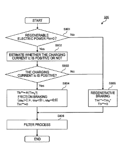
FIG. 8 is a flowchart illustrating the command value calculation
control. FIG. 8 illustrates processes S801 to S806 in the command value
calculation control. In these processes, the braking method is selected at
S801 and S803 and command values are obtained at S804 to S806.
[0109] At
Step S801, the motor controller 14 determines whether the
battery 2 can be regenerated by determining whether the regenerable electric
power Pin transmitted from the battery controller 13 is zero or not. That is,
when the regenerable electric power Pin is zero, (S801: Yes), the motor
controller 14 detei ______________________________________________________
mines that the battery 2 is possibly overcharged if the
regenerative braking is performed, and advances the process to S802. On the
other hand, when the regenerable electric power Pin is not zero (S801: No),
since the battery 2 has the available capacity, the motor controller 14
determines that the battery 2 is appropriately charged even if the
regenerative
CA 02994059 2018-01-29
- 24 -
braking is performed and selects the regenerative braking to advance the
process to S805.
[0110] At Step S802, the motor controller 14 calculates a charging current
Ic using the third torque target value Tm3* output from the comparator 504 in
FIG. 5 and the motor rotation speed m calculated at S301 in FIG. 3.
[0111] Here, the charging current Ic is a current that flows to the battery
2
when the regenerative braking is performed. That is, when all the
regenerative electric power of the motor 1 is consumed by the electric vehicle
100, the charging current Ic becomes negative. The charging current Ic
becomes negative just before stop of the vehicle, which is a state where the
vehicle speed decreases such that all the regenerative electric power of the
motor 1 becomes equal to or less than a power consumption consumed by the
electric vehicle 100. On the other hand, when the regenerative electric power
of the motor 1 is not entirely consumed by the electric vehicle 100 but is
charged to the battery 2, the charging current Ic becomes positive. That is,
the sign of the charging current Ic indicates a magnitude relationship between
the regenerative electric power of the motor 1 and the power consumption of
the electric vehicle 100. It should be noted that the regenerative electric
power means an electric power generated in the motor 1. The power
consumption means an electric power consumed by a rotatable drive in the
motor 1 and an electric power consumed in the inverter 3 and other electric
equipment.
[0112] FIG. 9 is a charging current table illustrating whether the charging
current Ic is positive or not corresponding to the motor torque command value
Tm* and the motor rotation speed om. It should be noted that in FIG. 9, a
horizontal axis indicates the motor rotation speed corn and a vertical axis
indicates the motor torque command value Tm*. It should be noted that the
third torque target value Tm3* used at S802 is equivalent to the motor torque
CA 02994059 2018-01-29
- 25 -
command value Tin*.
[0113] FIG. 9 illustrates whether the battery 2 is charged or discharged
when driving and regenerating in accordance with the motor torque command
value Tin are performed in a state where the motor 1 rotates at the motor
rotation speed cam. Here, the motor rotation speed cam indicates the running
condition of the electric vehicle 100, and the motor torque command value Trn*
is obtained according to the accelerator position. In addition to the
magnitude relationship between the regenerative electric power and the power
consumption, whether the battery 2 is charged or discharged is determined by
whether the regenerable electric power Pin is zero or not. Accordingly, FIG. 9
illustrates a predicted result of the magnitude relationship between the
regenerative electric power and the power consumption on the basis of the
accelerator position and the running condition of the electric vehicle 100.
[0114] Specifically, in FIG. 9, the hatched region is a discharge region
and
the regions without the hatching are charge regions. When the regenerative
braking is performed in the discharge region, it is predicted that the
regenerative electric power by the motor 1 falls below the power consumption
of the electric vehicle 100 and the battery 2 is discharged. Accordingly, the
charging current Ic becomes negative. On the other hand, when the
regenerative braking is perfoimed in the charge region, it is predicted that
the
regenerative electric power by the motor 1 exceeds the power consumption of
the electric vehicle 100 and the battery 2 is charged. Accordingly, the
charging current Ic becomes positive. It should be noted that when a position
referred in FIG. 9 is a boundary between the discharge region and the charge
region, the charging current Ic is zero.
[0115] With reference to FIG. 8 again, the motor controller 14 determines
whether the charging current Ic calculated at S802 is positive or not at Step
S803. When the charging current Ic is positive (8803: Yes), performing the
CA 02994059 2018-01-29
- 26 -
regenerative braking causes the regenerative electric power to exceed the
power consumption, resulting in overcharge of the battery 2. Therefore, the
motor controller 14 determines that the regenerative braking cannot be
performed and selects the friction braking to advance the process to S804.
On the other hand, when the charging current Ic is not positive (S803: No),
the
regenerative electric power becomes equal to or less than the power
consumption even when the regenerative braking is performed. Therefore,
the motor controller 14 determines that the regenerative braking can be
performed and selects the regenerative braking to advance the process to
S805.
[0116] It should be noted that, as a modification of S802 and S803, the
motor controller 14 may determine whether the charging current Ic is positive
or negative by determining whether the position referred by the third torque
target value Tm3* and the motor rotation speed 6.),, in FIG. 9 is the charge
region or the discharge region or not.
[0117] At Step S804, the motor controller 14 sets a motor torque command
value (before the filter process) Tm- and the friction torque command value
(before the filter process) Tb- used in the friction braking.
[0118] Specifically, the motor torque command value (before the filter
process) Tm** is set to 0. An absolute value of the third motor torque target
value Tm3* to which the sign identical to the sign of the angular velocity cow
of
the driving wheels 6 is attached is set as the friction torque command value
(before the filter process) Tb-. That is, when the angular velocity co, of the
driving wheels 6 is positive (aw > 0), that is, when the electric vehicle 100
moves forward, the friction torque command value (before the filter process)
Tb- becomes positive. When the angular velocity cow of the driving wheels 6 is
negative (caw < 0), that is, when the electric vehicle 100 moves backward, the
friction torque command value (before the filter process) Tb"* becomes
negative.
CA 02994059 2018-01-29
=
- 27 -
When the angular velocity OW of the driving wheel 6 is zero (cow = 0), that
is,
when the electric vehicle 100 stops, no friction braking is performed. Thus,
the sign of the friction torque command value (before the filter process) Tb*"
becomes zero.
[0119] On the other hand, at Step S805, the motor controller 14 sets
the
third torque target value Tm3* as the motor torque command value (before the
filter process) Tm** and sets zero as the friction torque command value
(before
the filter process) Tb"*.
[0120] At Step S806, the motor controller 14 performs the filter
process on
the motor torque command value (before the filter process) Tm** and the
friction torque command value (before the filter process) Tb** to calculate
the
motor torque command value Tm* and the friction torque command value Tb*.
The following describes the details of the filter process at S806 with
reference
to FIG. 10.
[0121] FIG. 10 is a block diagram illustrating the filter process at
S806
illustrated in FIG. 8.
[0122] As illustrated in FIG. 10, the command value calculating block
505
includes blocks 1001 and 1002.
[0123] The block 1001 is a filter Hba(s) that performs the filter
process on
the input motor torque command value (before the filter process) Tm*" and
outputs the motor torque command value Tm*. It should be noted that the
filter Hba(s) is expressed by the following Equation.
[01241 [Equation 141
CA 02994059 2018-01-29
0
- 28 -
H ba(S)
¨G ba(s) = H brk(s)
= = = ( 1 2)
Gpa(S)
[0125] It should be noted that a filter Hbrk(s) in the Equation
(12) is
expressed by the following equation.
[0126] [Equation 15]
2
b
Ilbric (s) = = = = ( 1 3)
+ 2 = COb = S COb2)
[0127] Note that a parameter in Equation (13) is as follows.
(JLb: unique vibration frequency when an actuator response in the friction
braking unit 7 is expressed by the second order vibration system.
[0128] The filter Hba(s) is a product of a transfer function
Gba(s), 1/ Gpa(s)
as an inverse transfer function of Gpa(s), and a filter Hbk(s). Therefore, the
output of the acceleration a of the electric vehicle 100 is obtained from the
input of the motor torque command value (before the filter process) Tm- with
the transfer function Gba(s). Furthermore, the acceleration a becomes the
input, and the driving torque of the motor 1 is obtained with the inverse
transfer function 1/Gpa(s). Then, the filter Hbrk(s) performs the filter
process
appropriate for the friction braking to obtain the motor torque command value
Tm".
[0129] The block 1002 is a filter Hinv(s) that performs the
filter process on
the input friction torque command value (before the filter process) Tb- and
outputs the friction torque command value Tb*. It should be noted that the
CA 02994059 2018-01-29
- 29 -
filter Hinv(s) is expressed by the following.
[0130] [Equation 16]
(s2 + 24- = w = s + co 2)
= ( 1 4 )
(s2 + 2-cop -s+c)p2)
[0131] Note that, parameters in Equation (14) are as follows.
cop: unique vibration frequency in the vehicle model
damping coefficient in the vehicle model
[0132] Use of such filter Hba(s) of the block 1001 and filter Hinv(s) of
the
block 1002 ensures uniforming responsiveness of the acceleration from the
motor torque and responsiveness of the acceleration from the friction braking
amount.
[0133] Here, as the friction braking unit 7 is hydraulic braking of slow
responsiveness while the responsiveness of the motor 1 is almost instant,
there is a difference in the responsiveness between the regenerative braking
and the friction braking. Accordingly, for example, as is the case of when the
regenerative braking and the friction braking are switched, even when the
motor torque command value (before the filter process) Tm** and the friction
torque command value (before the filter process) Tb** as the input values
rapidly change, performing the filtering process in the blocks 1001 and 1002
takes the difference in the responsiveness between the hydraulic braking and
the regenerative braking into consideration in the motor torque command
value Tm* and the friction torque command value Tb* as the output values.
[0134] Thus, in the filter process at S806, the use of the blocks 1001 and
1002 reduces the rapid change of the command value to the motor 1 and the
friction braking unit 7. Specifically, in the motor torque command value Tm*
CA 02994059 2018-01-29
- 30 -
as the command value to the motor 1, the rapid variation is reduced such that
the slow response of the friction braking unit 7 is compensated. Therefore, a
difference between the command value and the response value in the friction
braking unit 7 caused due to the slow responsiveness in the friction braking
unit 7 is compensated by the motor 1.
[0135] The
following describes the running conditions of the electric vehicle
100 with reference to FIG. 11.
[0136] FIG. 11 is
views illustrating the running conditions of the electric
vehicle 100. FIG. 11 illustrates the running conditions of the electric
vehicle
100 when the regenerable electric power Pin is zero and switching from the
friction braking to the regenerative braking is perfoi ___________ Hied (a
time tc) after the
electric vehicle 100 enters a state of just before stop of the vehicle (a time
t2).
[0137] FIG. 11
illustrates the running conditions of the electric vehicle 100
on (a) the uphill road, (b) the flat road, and (c) the downhill road. FIG. 11
illustrates the motor rotation speed 6),,, in (al), (hi), and (c 1) on the
uppermost
stage. In (a2), (b2), and (c2) on the second stage from the top, the motor
torque command value Tm* is illustrated in solid lines, the disturbance torque
estimated value Td is illustrated in one-dot chain lines, and the third torque
target value Tm3" is illustrated in two-dot chain lines. In (a3), (b3), and
(c3) on
the third stage from the top, the friction torque command value Tb* is
illustrated. In (a4), (b4), and (c4) on the lowermost stage, the acceleration
a of
the electric vehicle 100 is illustrated.
[0138] FIG. 12 is
charging current tables illustrating the running
conditions of the electric vehicle 100 in FIG. 11. FIG. 12 indicates changes
in
the charging current Ic until the electric vehicle 100 stops when the electric
vehicle 100 runs on the respective (a) uphill road, (b) flat road, and (c)
downhill
road by dotted lines.
[0139] First, the
following describes the running conditions of the electric
CA 02994059 2018-01-29
- 31 -
vehicle 100 at each time in FIG. 11.
[0140] At a time to, the accelerator position 0 is 0 and the electric
vehicle
100 starts decelerating by the friction braking. At the time t2, the electric
vehicle 100 is in the state of just before stop of the vehicle and switches
the
state to the braking using the disturbance torque estimated value Td. At the
time tc between the time t2 and a time t5, the braking method switches from
the friction braking to the regenerative braking. At the time t5, the electric
vehicle 100 stops.
[0141] Here, the following describes the running condition of the electric
vehicle 100 at the time tO at which the deceleration by the friction braking
is
started on the uphill road.
[0142] With reference to FIG. 11 (al), at the time tO, the electric vehicle
100
is in a state before the just before stop of the vehicle. The speed of the
electric
vehicle 100 monotonically decreases, thus monotonically reducing the motor
rotation speed cam.
[0143] With reference to FIG. 11 (a2), at the time tO, since the influence
from the gradient of the road surface is dominant, the disturbance torque
estimated value Td is a positive value according to the gradient of the uphill
road. It should be noted that the disturbance torque estimated value Td is
mostly the identical value since the influence from the gradient of the road
surface is dominant even at a time other than the time tO.
[0144] The third torque target value Tm3* is a predetermined negative value.
This can be described as follows.
[0145] The comparator 504 illustrated in FIG. 5 outputs the first torque
target value Tml* as the third torque target value Tm3* since the electric
vehicle
100 is not in the state of just before stop of the vehicle. Here, with
reference to
the torque table in FIG. 4, when the electric vehicle 100 is in the state of
just
before stop of the vehicle, that is, when the accelerator position 0 is zero
and
CA 02994059 2018-01-29
- 32 -
the motor rotation speed G.)ni is small, the first torque target value Tm 1*
is a
constant negative value. Accordingly, the third torque target value Tm3"
becomes the first torque target value Tmi* as the constant negative value.
[0146] The motor torque command value Tm* is zero. This can be
described as follows.
[0147] With reference to the command value calculation process in FIG. 8,
the regenerable electric power Pin is zero (S801: Yes), and the charging
current
Ic with the positive value is calculated at the process at S802. Therefore,
the
friction braking is selected (8803: No), and the motor torque command value
(before the filter process) Tm' becomes zero (S804). It should be noted that
the motor torque command value (before the filter process) Tm' is not varied.
Therefore, the motor torque command value Tm* through the block 1001 in
FIG. 10 also becomes zero (S806).
[0148] With reference to FIG. 11 (a3), at the time to, the friction torque
command value Tb* is set to an absolute value of the third torque target value
Tm3* illustrated in FIG. 11 (a2) with a positive sign. This is because, since
the
friction braking is performed as described above, the command value
calculation process in FIG. 8 sets the friction torque command value Tb* to a
value according to the third torque target value Tm3* at 8804.
[0149] With reference to FIG. 11 (a4), at the time tO, since the motor
rotation speed Win monotonically decreases as illustrated in FIG. 11 (al), the
acceleration a is constant at a negative value.
[0150] The following describes the running condition of the electric
vehicle
100 at the time t2 at which the electric vehicle 100 is in the state of just
before
stop of the vehicle on the uphill road.
[0151] With reference to FIG. 11 (al), at the time t2, since the electric
vehicle 100 is in the state of just before stop of the vehicle and switches to
the
motor rotation speed F/B control, a decreasing gradient of the motor rotation
CA 02994059 2018-01-29
- 33 -
speed com. decreases.
[0152] With reference to FIG. 11 (a2), at the time t2, the third torque
target
value Tm3* significantly changes. This is caused by the magnitude
relationship between the first torque target value Tmi* and the torque target
value Tm2* being reversed before and after the time t2 since the electric
vehicle
100 enters the state of just before stop of the vehicle. That is, the third
torque
target value Tm3* output from the comparator 504 in FIG. 5 is the first torque
target value Tmi" before the time t2 and is the second torque target value
Tm2"
after the time t2. It should be noted that, at the time t2, the first torque
target
value Tini* and the second torque target value Tm2* are identical values.
Therefore, the comparator 504 in FIG. 5 outputs any of the first torque target
value Tml" and the second torque target value Tm2* as the third torque target
value Tm3*.
[0153] After the time t2, the third torque target value Tm3* as the second
torque target value Tm2* converges to the disturbance torque estimated value
Td. This is because, with reference to FIG. 5, as the motor rotation speed F/B
torque To output from the motor rotation speed F/B torque setting block 501
decreases in association with the decrease of the motor rotation speed cam,
the
second torque target value Tm2* output from the adder 503 converges to the
disturbance torque estimated value Td output from the disturbance torque
estimating block 502.
[01541 The motor torque command value Tm* is zero. This is because,
similar to the time to, the regenerable electric power is zero (S801: Yes) in
the
command value calculation process illustrated in FIG. 8 and the charging
current Ic at the time t2 is positive in FIG. 12 (a) (S803: Yes); therefore,
the
friction braking is performed (S804, S806).
[0155] With reference to FIG. 11 (a3), at the time t2, the friction torque
command value Tb" is an absolute value of the third torque target value Tm3*
in
CA 02994059 2018-01-29
=
- 34 -
FIG. 11 (a2) with a positive sign, since the friction braking is performed as
described above. It should be noted that, after the time t2, the friction
torque
command value Tb" decreases in association with the increase of the third
torque target value Tm3*. It should be noted that, at the time t2, the change
in
the friction torque command value Tb* is gentler than the change in the third
torque target value Tm3". This is because the variation is reduced by the
process of the block 1002 in FIG. 10 at S806 in FIG. 8.
[0156] With reference to FIG. 11 (a4), at and after the time t2, the
electric
vehicle 100 is in the state of just before stop of the vehicle. Therefore, the
acceleration a gradually increases from the negative value due to the
decreasing gradient of the motor rotation speed 6.)m starting to be small as
illustrated in FIG. 11 (a2).
[0157] Next, the following describes the running condition of the
electric
vehicle 100 at the time tc at which the braking method switches from the
friction braking to the regenerative braking on the uphill road.
[0158] With reference to FIG. 11 (al), at the time tc, the motor
rotation
speed cam is a value close to zero. This is because, as described above, the
motor rotation speed con, converges to zero after the time t2 at which the
electric
vehicle 100 is in the state of just before stop of the vehicle.
[0159] With reference to FIG. 11 (a2), at the time tc, the third
torque target
value Tm3* is a value close to the disturbance torque estimated value Td. This
is because, as described above, the third torque target value Tm3" converges
to
the disturbance torque estimated value Td after the time t2 at which the
electric vehicle 100 is in the state of just before stop of the vehicle.
[0160] The motor torque command value Tm" is zero at the time tc and
converges to the third torque target value Tm3" with the lapse of time after
the
time tc. This is because the motor controller 14 performs the following
operation.
CA 02994059 2018-01-29
- 35 -
[0161] With reference to the command value calculation process illustrated
in FIG. 8, before the time tc, the regenerable electric power is zero (S801:
Yes),
the positive charging current Ic is calculated (S802), the friction braking is
selected (S803: Yes), the motor torque command value (before the filter
process) Tm** is set to zero (S804). On the other hand, at the time tc, the
regenerable electric power is zero (S801: Yes), the charging current Ic of
zero is
calculated (S802), the regenerative braking is selected (S803: No), and the
motor torque command value (before the filter process) Tm"* is set to the
third
torque target value Tm3* (S805).
[0162] Accordingly, the motor torque command value (before the filter
process) Tm** is set to zero before the time tc (S804) and is set to the third
torque target value Tm3* at and after the time tc (S805). Therefore, the motor
torque command value (before the filter process) Tm- rapidly varies.
[0163] However, performing the process of the block 1001 in FIG. 10 at
S806 reduces the variation in the motor torque command value Tm* after the
filter process. Therefore, the motor torque command value Tm* that is zero at
the time tc converges to the third torque target value Tm3" with the lapse of
time.
[0164] It should be noted that, at the block 1001, as illustrated in
Equation
(12), the delay of the responsiveness of the friction braking unit 7 is taken
into
consideration. Therefore, the change in the motor torque command value
Tm* is reduced such that an excess amount of the friction braking torque
caused by the delay of the responsiveness by the friction braking unit 7 is
compensated. In view of this, the friction torque amount caused by the slow
responsiveness of the friction braking unit 7 is compensated by the driving
force of the motor 1 when the braking method is switched from the friction
braking to the regenerative braking.
[0165] With reference to FIG. 11 (a3), the friction torque command value
CA 02994059 2018-01-29
- 36 -
Tb* is a value found by performing the filter process on the absolute value of
the third torque target value Tm3" with a positive sign at the time tc, and
converges to zero with the lapse of time after the time tc. Such change in the
friction torque command value Tb* can be described as follows.
[0166] As described above, in the command value calculation process in
FIG. 8, the friction braking is performed before the time tc (S804), and the
regenerative braking is performed at and after the time tc (S805).
[01671 Accordingly, the friction torque command value (before the filter
process) Tb** is set to an absolute value of the third torque target value
Tm3*
with a positive sign before the time tc (S804), and is set to zero at and
after the
time tc (S805). Therefore, the friction torque command value (before the
filter
process) Tb** rapidly changes.
[0168] However, performing the process of the block 1002 in FIG. 10 at
S806 reduces the variation of the friction torque command value Tb* after the
filter process. Therefore, the friction torque command value Tb* as a value
found by performing the filter process on the third torque target value Tm3*
converges to zero with the lapse of time.
[0169] With reference to FIG. 11 (a4), the decreasing gradient of the motor
rotation speed u),,, decreases as illustrated in FIG. 11 (al) at the time tc.
Therefore, the change in the acceleration a gradually decreases.
[0170] The following describes the running condition of the electric
vehicle
100 at the time t5 at which the electric vehicle 100 stops on the uphill road.
[0171] With reference to FIG. 11 (al), the electric vehicle 100 stops at
the
time t5. Therefore, the motor rotation speed Cm is zero.
[0172] With reference to FIG. 11 (a2), the motor torque command value Tm*
matches the third torque target value Tm3* at the time t5. This is because the
motor 1 generates the torque (S805 and S806) since, as described above, after
the time tc, in the command value calculation process illustrated in FIG. 8,
the
CA 02994059 2018-01-29
- 37 -
regenerable electric power is zero (S801: Yes), and the charging current Ic
calculated at S802 is negative at the time t5 (S803: No). This prevents the
electric vehicle 100 from rolling down on the uphill road by the motor 1
generating the torque.
[0173] As described above, the third torque target value Tm3* converges to
the disturbance torque estimated value Td at and after the time t2. Therefore,
the motor torque command value Tm* matches the disturbance torque
estimated value Td corresponding to the gradient when the electric vehicle 100
stops at the time t5. Accordingly, the motor 1 generating the positive driving
torque that reduces the influence of the gradient ensures the electric vehicle
100 keeping the vehicle stop state on the uphill road.
[0174] With reference to FIG. 11 (a3), at the time t5, the regenerative
braking is selected in the target value calculation process in FIG. 8 (S803:
No);
therefore, the friction torque command value Tb* becomes zero (S805 and
S806).
[0175] With reference to FIG. 11 (a4), at the time t5, the acceleration a
becomes a positive value such that the electric vehicle 100 keeps the vehicle
stop state on the uphill road. This is because, as illustrated in FIG. 11
(a2), at
the time t5, the motor 1 generates the driving torque in accordance with the
motor torque command value Tm*, which is the disturbance torque estimated
value Td.
[0176] Thus, on (a) the uphill road, the above-described processes are
performed at the respective times. It should be noted that, on (b) the flat
road
and (c) the downhill road, the control sequence identical to that of on (a)
the
uphill road is performed.
[0177] However, in the cases of on (b) the flat road and (c) the downhill
road,
the disturbance torque estimated value Td calculated in the disturbance
torque estimating block 502 in FIG. 5 is different from the case of on (a) the
CA 02994059 2018-01-29
- 38 -
uphill road. The disturbance torque estimated value Td is a value
corresponding to the gradient. With reference to FIG. 11 (b2), the disturbance
torque estimated value Td becomes zero on (b) the flat road. With reference to
FIG. 11 (c2), the disturbance torque estimated value Td becomes negative on
(c) the downhill road.
[0178] Next, with reference to FIG. 13, the following describes other
operations of the electric vehicle 100.
[0179] FIG. 13 is views illustrating the running conditions of the electric
vehicle 100. Compared with FIG. 11, FIG. 13 is identical in that the
regenerable electric power Pin is zero and is different in that the switching
from
friction braking to the regenerative braking is performed (the time tc) before
the
electric vehicle 100 enters a state of just before stop of the vehicle (the
time t2).
[0180] It should be noted that FIG. 13 illustrates the cases of (a) the
uphill
road, (b) the flat road, and (c) the downhill road similar to FIG. 11. In each
of
(a) the uphill road, (b) the flat road, and (c) the downhill road, the motor
rotation speed 6)õõ the motor torque command value Tm", the friction torque
command value Tb*, and the acceleration a are illustrated in an order from the
top.
[0181] FIG. 14 is a charging current table illustrating the running
conditions of the electric vehicle 100 in FIG. 13. FIG. 14, similar to FIG.
12,
illustrates when the electric vehicle 100 runs on each of (a) the uphill road,
(b)
the flat road, and (c) the downhill road.
[0182] Next, the following describes operations of the electric vehicle 100
at
the respective times in FIG. 13.
[0183] As described above, compared with FIG. 11, FIG. 13 is different in
that the electric vehicle 100 enters the state of just before stop of the
vehicle
(the time t2) after the switching from the friction braking to the
regenerative
braking is performed (the time tc). Therefore, the following describes the
CA 02994059 2018-01-29
1
- 39 -
operations of the electric vehicle 100 at the times tc and t2, and the
descriptions of the other times are omitted.
[0184] First, the
operation of the electric vehicle 100 at the time tc at which
the braking method is switched from the friction braking to the regenerative
braking on the uphill road.
[0185] With reference
to FIG. 13 (al), at the time tc, the motor rotation
speed cam monotonically decreases and a decreasing pace is not changed.
This is because before and after the time tc, only the switching of the
braking
method is performed, and the braking force generated in the electric vehicle
100 is not changed.
[0186] Describing in
details, with reference to the command value
calculation process in FIG. 8, the regenerable electric power is zero before
the
time tc (S801: Yes), the positive charging current Ic is calculated (S802),
and
the friction braking is selected (S803: Yes). Then, the friction torque
command value Tb* becomes a value found by performing the filter process on
the third torque target value Tm3* (S804 and S806).
[0187] On the other
hand, at the time tc, the regenerable electric power is
zero (S801: Yes), the charging current Ic of zero is calculated (S802), and
the
regenerative braking is selected (S803: No). Then, the motor torque command
value Tm* becomes the value found by performing the filter process on the
third torque target value Tm3* (S805 and S806).
[0188] That is, before
the time tc, the friction braking on the basis of the
third torque target value Tm3* is performed, and at and after the time tc, the
braking method is gradually switched to the regenerative braking on the basis
of the third torque target value Tm3*. Accordingly, before and after the time
tc,
while the braking methods are different, the braking force generated in the
electric vehicle 100 does not change. Accordingly, at the time tc, the
decreasing gradient of the motor rotation speed cAm does not change.
CA 02994059 2018-01-29
- 40 -
[0189] With reference to FIG. 13 (a2), at the time tc, the third torque
target
value Tm3" is a predetelinined negative value similar to the time tO.
[0190] The motor torque command value Tm* is zero at the time tc, and
converges to the third torque target value Tm3* with the lapse of time after
the
time tc.
[0191] Such changes of the third torque target value Tm3* and the motor
torque command value Tm* are similar to the changes of the third torque target
value Tm3" and the motor torque command value Tm* at the time tc in FIG. 11
(a2) described above. Therefore, employing the description in FIG. 11 (a2) can
make a description.
[0192] With reference to FIG. 13 (a3), the friction torque command value
Tb* is a value found by attaching a negative sign to the third torque target
value Tm3* at the time tc, and converges to zero with the lapse of time after
the
time tc.
[0193] Such change of the friction torque command value Tb* is similar to
the change of the friction torque command value Tb* at the time tc in FIG. 11
(a3) as described above. Therefore, employing the description in FIG. 11 (a3)
can make a description.
[0194] With reference to FIG. 13 (a4), at the time tc, as illustrated in
FIG. 13
(al), the motor rotation speed cam monotonically decreases. Therefore, the
acceleration a is a constant negative value.
[0195] Next, the following describes the operation of the electric vehicle
100
at the time t2 at which the electric vehicle 100 enters the state of just
before
stop of the vehicle on the uphill road.
[0196] With reference to FIG. 13 (al), at the time t2, the electric vehicle
100
enters the state of just before stop of the vehicle. Therefore, the decreasing
pace of the motor rotation speed com starts to slow down so as to stop
smoothly.
[0197] With reference to FIG. 13 (a2), the motor torque command value Tm*
CA 02994059 2018-01-29
- 41 -
matches the third torque target value Tm3". This is because, in the command
value calculation process illustrated in FIG. 8, the regenerable electric
power is
zero (S801: Yes), the negative charging current Ic is calculated at S802
(S802),
the regenerative braking is selected (S803: No), and the motor torque
command value Tm* becomes a value corresponding to the third torque target
value Tm3" (S805 and S806).
[0198] With
reference to FIG. 13 (a3), at the time t2, the regenerative
braking is performed. Therefore, the friction torque command value Tb"
becomes zero (S805 and S806).
[0199] With
reference to FIG. 13 (a4), at the time t2, the electric vehicle 100
entering the state of just before stop of the vehicle decreases the decreasing
gradient of the motor rotation speed corn as illustrated in FIG. 13 (al).
Therefore, the acceleration a gradually increases from the negative value.
[0200] It should
be noted that while on (a) the uphill road, the
above-described processes are performed at the respective times, the identical
operations are performed at the identical timing to (a) the uphill road as
well as
on (b) the flat road and (c) the downhill road. It should be noted that the
disturbance torque estimated value Td is a value caused by the gradient. As
illustrated in FIG. 13 (b2), the disturbance torque estimated value Td is zero
on
(b) the flat road. As illustrated in FIG. 13 (c2), the disturbance torque
estimated value Td is negative on (c) the downhill road.
[0201] It should
be noted that the motor controller 14 may predict a value
of the charging current Ic using an equation that modeled the regenerative
electric power of the motor 1 and the power consumption of the electric
vehicle
100.
[0202] The first embodiment provides the following effects.
[0203] The vehicle
that executes driving and braking of the motor
corresponding to the opening degree of the accelerator pedal needs to stop by
CA 02994059 2018-01-29
=
- 42 -
adjusting the braking force corresponding to the disturbance. However, in
this embodiment, just before stop of the vehicle, the regenerative braking,
which is excellent in the controllability (such as a control responsiveness
and a
control accuracy) with respect to the friction braking, is executed to
appropriately perform the braking corresponding to the disturbance.
Therefore, the electric vehicle 100 can be stopped smoothly.
[0204] The control device of the electric vehicle in the first
embodiment
includes the motor 1, the friction braking unit 7, and the motor controller
14.
The motor 1 generates the driving force or the regenerative braking force of
the
electric vehicle 100. The friction braking unit 7 generates the friction
braking
force. The motor controller 14 controls at least one of the motor 1 and the
friction braking unit 7 corresponding to the opening degree of the accelerator
pedal.
[0205] Here, with reference to the command value calculation process
in
FIG. 8, the motor controller 14 calculates the charging current lc that flows
toward the battery 2 when the regenerative braking is performed (S802), and
determines positive or negative of the calculated charging current Ic (S803).
When the regenerative electric power generated by the motor 1 exceeds the
power consumption in the electric vehicle 100 when the braking force is
generated by the motor 1 alone, the charging current Ic becomes positive. On
the other hand, when the regenerative electric power generated by the motor 1
falls below the power consumption in the electric vehicle 100, the charging
current Ic becomes negative. Accordingly, determining positive or negative of
the charging current lc (S803) ensures determining whether all the
regenerative electric power generated by the motor 1 is consumed in the
electric vehicle 100 or not when the braking force is generated by the motor 1
alone.
[0206] When the regenerable electric power Pin is zero (S801: Yes),
the
CA 02994059 2018-01-29
- 43 -
battery 2 is possibly overcharged if the regenerative braking is performed.
However, even when the regenerable electric power Pin is zero, when the
charging current Ic that flows toward the battery 2 when the regenerative
braking is performed is calculated to be negative, that is, when all the
regenerative electric power of the motor 1 is consumed by the motor 1 and the
inverter 3 in the electric vehicle 100 (S803: No), the battery 2 is not
charged
even if the regenerative braking is performed. Therefore, even if the
regenerable electric power Pin is in a state of zero, the motor controller 14
selects the regenerative braking (S805), and causes the motor 1 to perform the
regenerative braking.
[0207] Here, immediately before the electric vehicle 100 stops, since the
vehicle speed is close to zero, the regenerative electric power of the motor 1
is
small. Therefore, all the regenerative electric power is consumed in the
electric vehicle 100, thus, the battery 2 discharges and the charging current
Ic
becomes negative. Thus, immediately before the electric vehicle 100 stops,
the charging current Ic is constantly negative (S803: No), thereby ensuring
performing the regenerative braking. Accordingly, the electric vehicle 100 can
be stopped by the regenerative braking (S805) regardless of how much the
remaining amount of the battery 2 is. Therefore, the acceleration vibration
when the electric vehicle 100 is stopped can be reduced, and the electric
vehicle 100 can be smoothly decelerated to stop.
[0208] As a modification of S802 and S803 executed by the motor controller
14 as the control device in the first embodiment, the motor controller 14 may
determine positive or negative of the charging current Ic using the charging
current table in FIG. 9. The charging current table illustrates positive or
negative of the charging current Ic on the basis of the motor torque command
value corresponding to the operation of the accelerator and the motor rotation
speed ck)rn corresponding to the running condition of the electric vehicle
100.
CA 02994059 2018-01-29
- 44 -
Thus, only by the motor torque command value Tm* and the motor rotation
speed cam, positive or negative of the charging current Ic can be determined,
thereby ensuring decreasing a load of arithmetic processing in the motor
controller 14.
[0209] It should be noted that, with reference to the charging current
table
in FIG. 9, when the motor rotation speed Gam is a value at the proximity of
zero,
that is, when the electric vehicle 100 is in the state of immediately before
stop,
since it is in the discharge region regardless of the magnitude of the motor
torque command value Tc, the charging current Ic is negative.
[0210] Thus, in the state of immediately before the electric vehicle 100
stops, since the charging current lc is negative (S803: No), the motor
controller
14 causes the motor 1 to perform the regenerative braking (S805).
Accordingly, the electric vehicle 100 can be stopped by the regenerative
braking regardless of how much the remaining amount of the battery 2 is.
Therefore, causing the motor 1 to perform the regenerative braking when the
charging current Ic is determined to be negative using the charging current
table ensures smoothly decelerating and stopping the electric vehicle 100.
[0211] With the motor controller 14 that is the control device of the first
embodiment, with reference to the command value calculation process in FIG.
8, at S806, the filter process is performed on the motor torque command value
(before the filter process) Tm- and the friction torque command value (before
the filter process) Tb.* that are obtained at S804 or S805, thus obtaining the
motor torque command value Tm* and the friction torque command value Tb..
[0212] In this filter process, the use of the filter Hba(s) of the block
1001
and the filter Hinv(s) of the block 1002 ensures uniforming the responsiveness
of the acceleration from the motor torque and the responsiveness of the
acceleration from the friction braking amount.
[0213] Accordingly, by the use of the block 1001, the responsiveness of the
CA 02994059 2018-01-29
- 45 -
friction braking unit 7 slower than the responsiveness of the motor 1 is
considered. Thus, the regenerative braking force by the motor 1 is reduced so
as to compensate the delay of this responsiveness.
[0214] Here, by using the operation of the electric vehicle 100 at the time
when transition is performed from the charge area to the discharge region in
the charging current table in FIG. 9, that is, the time tc in FIG. 11 to 14,
the
effect by the above-described filter process by the block 1001 will be
described.
At this time tc, in the command value calculation process in FIG. 8, the motor
controller 14 performs switching from the friction braking (S804) to the
regenerative braking (S805).
[0215] At this time tc, the friction torque command value (before the
filter
process) Tb** that will be the command value to the friction braking unit 7
significantly changes from a value on the basis of the third torque target
value
Tm3 (S804) to zero (S805). Therefore, at the time tc, it is preferable that
the
friction braking torque by the friction braking unit 7 becomes zero. However,
the friction braking torque by the friction braking unit 7 becomes a value
greater than the command value due to the slow responsiveness in the friction
braking unit 7.
[0216] In contrast, the motor torque command value (before the filter
process) Tm** that will be the command value to the motor 1 significantly
changes from zero (S804) to the third torque target value Tm3 (S805). Here, at
the block 1001 in FIG. 10 in the filter process at S806, that is, at the motor
torque command value Tm* after the process in Equation (12), the slow
responsiveness in the friction braking unit 7 is taken into consideration to
reduce the variation.
[0217] Therefore, when the variation of the motor torque command value
Tm* output from the block 1001 is reduced, the control is performed to
generate the driving torque in the motor 1 so as to compensate the friction
CA 02994059 2018-01-29
=
- 46 -
braking force due to the slow responsiveness generated in the friction braking
unit 7. Accordingly, when the switching from the friction braking to the
regenerative braking at the time tc is performed, accelerated vibration and
variation due to the slow responsiveness in the friction braking unit 7 can be
reduced.
[0218] With the motor controller 14 that is the control device of the
first
embodiment, with reference to the stop control process in FIG. 5, at the
disturbance torque estimating block 502, the disturbance torque estimated
value Td necessary for the electric vehicle to hold the vehicle stop state
corresponding to the disturbance that acts on the electric vehicle 100 is
obtained using the vehicle model. Then, when the electric vehicle 100 is in
the state of just before stop of the vehicle, the motor torque command value
Tm* output from the adder 503 becomes a sum of the motor rotation speed
F/B torque Tca output from the motor rotation speed F/B torque setting block
501 and the disturbance torque estimated value Td output from the
disturbance torque estimating block 502.
[0219] Here, when the electric vehicle 100 is in the state of just
before stop
of the vehicle, the motor rotation speed F/B torque Tca output from the motor
rotation speed F/B torque setting block 501 converges to zero. Accordingly,
the motor torque command value Trn* converges to the disturbance torque
estimated value Td to converge the torque generated in the motor 1 to the
value
corresponding to the gradient. Thus, the electric vehicle 100 can be smoothly
stopped. Furthermore, when the electric vehicle 100 stops, the motor 1
generates the torque corresponding to influence of the disturbance such as the
gradient that acts on the electric vehicle 100. Thus, even at the position
having the gradient, the vehicle stop state can be maintained without using
the
brake pedal.
[0220] (Second Embodiment)
CA 02994059 2018-01-29
- 47 -
The following describes a control device of a second embodiment. This
embodiment describes a case where a timing that the braking method switches
from the friction braking to the regenerative braking is different from that
in
the first embodiment.
[0221] FIG. 15 is a configuration diagram of an electric vehicle 100
including a motor controller 14 as the control device of the second
embodiment.
[0222] With reference to FIG. 15, the electric vehicle 100 of the second
embodiment is different from the electric vehicle 100 of the first embodiment
illustrated in FIG. 1, in that the regenerable electric power Pin is not
output
from the battery controller 13 to the motor controller 14.
[0223] The motor controller 14 preliminarily stores an SOC specified value
(SOCO) used for obtaining a switching timing between the friction braking and
the regenerative braking. It should be noted that the SOC specified value
(SOCO) can be obtained as follows.
[0224] First, a charging electric energy of the battery 2 in a period after
the
electric vehicle 100 has entered the state of just before stop of the vehicle
and
before the electric vehicle 100 has become in an equal power state where the
regenerative electric power of the motor 1 is equal to the power consumption
of
the electric vehicle 100 is obtained as a specified charging electric energy
Ws0
with calculation or experiment. It should be noted that the equal power state
corresponds to boundaries between the charge region and the discharge region
in the charging current table in FIG. 9.
[0225] Here, the specified charging electric energy Ws0 is different
depending on, for example, the gradient of the road surface and an operating
point of the motor 1. Therefore, corresponding to combinations of the
gradient, the operating point of the motor 1, and the like that are possibly
considered, a plurality of charging electric powers of the battery 2 until the
CA 02994059 2018-01-29
- 48 -
electric vehicle 100 has become in the equal power state are calculated with,
for example, the experiment or the calculation. The maximum value among
these calculated values can be obtained as the specified charging electric
energy Ws0.
[0226] Then, using the specified charging electric energy Ws0 and the
maximum capacity Wmax of the battery 2, SOCO as the SOC specified value is
obtained in following Equation (15).
[0227] [Equation 17]
W max¨ Ws0 x 1 00EN SOCO = = = = ( 1 5)
W max
[0228] When this embodiment is compared with the first embodiment, for
the processes by the motor controller 14, the processes illustrated in FIG. 3,
FIG. 6, and FIG. 7 are identical, and the stop control process in FIG. 5 and
the
command value calculation process in FIG. 8 are different. Therefore, the
following describes the stop control process and the command value
calculation process.
[0229] FIG. 16 is a block diagram illustrating the stop control process of
the
second embodiment.
[0230] The stop control process illustrated in FIG. 16, compared with the
stop control process of the first embodiment illustrated in FIG. 5, is
different in
that the SOC, not the regenerable electric power Pin, is input to the command
value calculating block 505, that the first torque target value Tm 1. and the
second torque target value Tm2 are additionally input, and that the motor
rotation speed 63m is not input, and other configurations are identical.
[0231] FIG. 17 is a flowchart illustrating the command value calculation
process of the second embodiment.
[0232] The command
value calculation process illustrated in FIG. 17,
CA 02994059 2018-01-29
- 49 -
compared with the command value calculation process of the first embodiment
illustrated in FIG. 8, S801 to S803 are removed, and S1701 and S1702 are
added.
[0233] At Step S1701, the motor controller 14 determines whether it is in
the state of just before stop of the vehicle or not by comparing the first
torque
target value Tm 1. to the second torque target value Tm2., to determine
whether
the regenerative braking is started.
[0234] When the first torque target value Tmi* is greater than the second
torque target value Tm2. (S1701: Yes), the electric vehicle 100 is determined
not in the state of just before stop of the vehicle. In such a case, the motor
controller 14 advances the process to S1702.
[0235] On the other hand, when the first torque target value Tmr* is equal
to or less than the second torque target value Tm2. (S1701: No), the electric
vehicle 100 is determined in the state of just before stop of the vehicle. In
such a case, the motor controller 14 advances the process to S805 to perform
the regenerative braking.
[0236] At Step S1702, the command value calculating block 505
determines whether the SOC transmitted from the battery controller 13 is
equal to or more than the SOC specified value not.
[0237] .. When the SOC is equal to or more than the SOC specified value
(S1702: Yes), the motor controller 14 selects the friction braking to advance
the process to S804.
[0238] On the other hand, when the SOC is smaller than the SOC specified
value (S1702: No), the motor controller 14 selects the regenerative braking to
advance the process to S805.
[0239] Here, the processes at S1701 and S1702 will be described by
dividing the case where the electric vehicle 100 is in the ordinary running
state
not in the state of just before stop of the vehicle from the case where the
CA 02994059 2018-01-29
- 50 -
electric vehicle 100 is in the state of just before stop of the vehicle.
[0240] First, the case
where the electric vehicle 100 is in the ordinary
running state will be described.
[0241] At S1701, the
electric vehicle 100 is in the ordinary running state
not in the state of just before stop of the vehicle. Since the first torque
target
value Tin'* is greater than the second torque target value Tm2. (S1701: Yes),
the motor controller 14 advances the process to the process at S1702.
[0242] At S1702, when the SOC is equal to or more than the SOC specified
value (S1702: Yes), the friction braking is selected to advance the process to
S804. On the other hand, when the SOC is smaller than the SOC specified
value (S1702: No), the regenerative braking is selected to advance the process
to S805.
[0243] Accordingly, when
the electric vehicle 100 is in the ordinary running
state, such processes are performed to charge the battery 2 up to the
capacitance that the SOC does not exceed the SOC specified value.
Accordingly, at the timing when the electric vehicle 100 becomes in the state
of
just before stop of the vehicle from the running state, the SOC of the battery
2
does not exceed the SOC specified value, and becomes a value close to the SOC
specified value.
[0244] The following
describes the case where the electric vehicle 100 is in
the state of just before stop of the vehicle.
[0245] At S1701, the
electric vehicle 100 is in the state of just before stop of
the vehicle. Since the first torque target value Tmi- is equal to or less than
the
second torque target value Tm2. (S1701: No), the motor controller 14 selects
the regenerative braking to advance the process to the process at S805.
[0246] As
described above, in the state of just before stop of the vehicle, the
SOC of the battery 2 does not exceed the SOC specified value. Therefore, in
the battery 2, there is an available capacity equal to or more than the
specified
CA 02994059 2018-01-29
- 51 -
charging electric energy Ws0.
[0247] Accordingly, in the state of just before stop of the vehicle (S1701:
No),
such that the motor controller 14 selects the regenerative braking (S805),
even
if the battery 2 is charged by the specified charging electric energy Ws0
until
becoming in the equal power state, the battery 2 is not overcharged.
[0248] As described above, at S1701 and S1702, the motor controller 14
generates the regenerative braking force by the motor 1 from the time point
when the electric vehicle 100 has entered the state of just before stop of the
vehicle, thus starting vehicle stop control to stop the electric vehicle 100
(S1701: NO, S805). In such a case, after the stop control starts and before
the
regenerative electric power by the motor 1 and the power consumption
consumed by the electric vehicle 100 become equal, the battery 2 will be
charged by the specified charging electric energy Ws0. Therefore, before the
electric vehicle 100 becomes in the state of just before stop of the vehicle,
that
is, before the vehicle stop control is started, such that the available
capacity of
the battery 2 becomes equal to or more than the specified charging electric
energy Ws0, the generation of the regenerative braking force by the motor 1 is
controlled (S1701: Yes, S1702).
[0249] It should be noted that, in this embodiment, the processes at S801
to S803 in FIG. 8 in the first embodiment are not performed. However, the
processes at S801 to S803 may be performed. For example, even in the case
where the SOC of the battery 2 is exceeding the SOC specified value, when the
electric vehicle 100 becomes in the state of just before stop of the vehicle
(S1701: No), the regenerative braking is possibly performed (S805). In such a
case, before becoming in the equal power state, the SOC of the battery 2
possibly becomes 100% to overcharge the battery 2. However, by performing
the processes at S801 to S803, when the battery 2 is fully charged, the
regenerable electric power Pin is zero (S801). Thus, depending on the size of
CA 02994059 2018-01-29
- 52 -
the charging current Ic, the friction braking or the regenerative braking is
selected (S802 to S805). Accordingly, this can prevent the battery 2 from
being overcharged, similar to the first embodiment.
[0250] The battery controller 13 and the motor controller 14 may include a
charge control device that controls the charge of the battery 2 so that the
SOC
of the battery 2 is equal to or less than the SOC specified value before the
predetermined timing. For example, in the case where the electric vehicle 100
is running on a freeway or the like, and the vehicle speed is faster than a
predetermined lower limit speed, the charge control device performs the
regenerative braking such that the SOC does not exceed the SOC specified
value. Thus, since the available capacity of the battery 2 is equal to or more
than the specified charging electric energy Ws0 on a high-speed vehicle area,
the vehicle can stop by the regenerative braking, and further, by increasing
the
remaining amount of the battery 2, a runnable distance of the electric vehicle
100 can be extended.
[0251] In this embodiment, the timing when the first torque target value
Trill- becomes smaller than the second torque target value Tm2* is the timing
to
start the regenerative braking, by being assumed as the timing when the
electric vehicle 100 becomes in the state of just before stop of the vehicle.
However, it is not limited to this. For example, a timing when the speed of
the
electric vehicle 100 becomes equal to or less than a predetermined speed (for
example, 20 km/h) may be the timing to start the regenerative braking, by
being assumed as the timing when the electric vehicle 100 becomes in a
low-speed state. In such a case, the motor controller 14, as the specified
charging electric energy Ws0, preliminarily stores the electric power by which
the battery 2 is charged after the speed of the electric vehicle 100 has
become
equal to or less than the predetermined speed and before becoming in the
equal power state. Then, at S1701, whether the speed of the electric vehicle
CA 02994059 2018-01-29
- 53 -
100 exceeds the predetermined speed or not is determined.
[0252] The effect by the second embodiment will be described by referring
to the charging current table in FIG. 18.
[0253] FIG. 18 is an exemplary charging current table, on which change in
the running state of the electric vehicle 100 according to the embodiment is
indicated with the dotted line.
[0254] For example, at the time t2, the electric vehicle 100 is determined
to
be in the state of just before stop of the vehicle (S1701: No). In such a
case,
the electric vehicle 100 has entered the state of just before stop of the
vehicle,
and before the regenerative electric power and power consumption become
equal, that is, before reaching the boundary between the discharge region and
the charge region, the battery 2 will be charged by the specified charging
electric energy Ws0. As described above, when the electric vehicle 100 is in
the state of just before stop of the vehicle, the SOC is equal to or less than
the
SOC specified value. That is, since the available capacity of the battery 2 is
equal to or more than the specified charging electric energy Ws0, the motor
controller 14 starts the regenerative braking (S805). Accordingly, in this
embodiment, the regenerative braking is started from the time t2.
[0255] On the other hand, in the first embodiment, for example, with
reference to FIG. 12 (b), the regenerative braking starts from the time tc
when
the transition is performed from the charge region to the discharge region.
Therefore, in the second embodiment, the time to perform the regenerative
braking is long compared with the first embodiment. Accordingly, the vehicle
can stop by the regenerative braking irrespective of the remaining amount of
the battery 2, and further, an opportunity to perform the regenerative braking
increases. Thus, the accelerated vibration and the variation can be further
reduced when the vehicle stops.
[0256] It should be noted that, in the command value calculation process
CA 02994059 2018-01-29
- 54 -
in FIG. 17, by further performing the processes at S801 to S803 in the first
embodiment, the battery 2 can be prevented from being overcharged. After
the electric vehicle 100 has entered the state of just before stop of the
vehicle,
and further, even in the discharge region in the charging current table as
illustrated in FIG. 18 or the like, the regenerative braking can be performed.
Furthermore, since the opportunity to perform the regenerative braking
increases, the accelerated vibration and the variation can be further reduced
when the vehicle stops.
[0257] According to the motor controller 14 that is the control device of
the
second embodiment, before the electric vehicle 100 becomes in the state of
just
before stop of the vehicle, the charge of the battery 2 is controlled so that
the
available capacity of the battery 2 is equal to or more than the specified
charging electric energy Ws0. Therefore, when the electric vehicle 100
becomes in the state of just before stop (S1701: Yes), the SOC of the battery
2
is equal to or less than the SOC specified value. Thus, even if the
regenerative
braking is performed (S805), the battery 2 is not overcharged.
[0258] The second embodiment provides the following effects.
[0259] The control device of the electric vehicle of the second embodiment,
when the electric vehicle 100 becomes just before stop of the vehicle,
generates
the regenerative braking force by the motor 1 to start the vehicle stop
control to
stop the electric vehicle 100 (S1701: NO, S805). After this vehicle stop
control
starts, and before the regenerative electric power and the power consumption
consumed in the electric vehicle 100 become equal, the battery 2 is charged by
the specified charging electric energy Ws0. Therefore, by the state of just
before stop of the vehicle, that is, by the start of the vehicle stop control,
the
generation of the regenerative braking force by the motor 1 is controlled so
that
the available capacity of the battery 2 is equal to or more than the specified
charging electric energy Ws0 (S1701: Yes, S1702).
CA 02994059 2018-01-29
= =
- 55 -
[0260] Thus, in the time point when the regenerative electric power and the
power consumption in the electric vehicle 100 become equal, the battery 2 is
charged by the specified charging electric energy Ws0 to make the battery 2 be
in the full charge state. Thus, compared with the first embodiment, the
runnable distance of the electric vehicle 100 in the vehicle stop state can be
made long. By performing the regenerative braking before the regenerative
electric power and the power consumption consumed by the electric vehicle
100 become equal, the time to perfoiiii the regenerative braking until the
electric vehicle 100 stops can be made long. Thus, the electric vehicle 100
can further smoothly stop.
[0261] (Third Embodiment)
Next, a description will be given of the electric vehicle 100 that includes a
control device of a third embodiment. In the second embodiment, as the
specified charging electric energy Ws0, a regenerative electric energy
generated
between a time point at which the electric vehicle 100 becomes in the state of
just before stop of the vehicle and a time point at which the vehicle stops is
preliminarily predicted. In this embodiment, a description will be given of an
example where the charging electric energy Ws is predicted corresponding to a
running state of the electric vehicle 100.
[0262] The electric vehicle 100 of the third embodiment has a configuration
identical to the configuration of the electric vehicle 100 of the first
embodiment
illustrated in FIG. 1. Then, the explanation of the configuration will be
omitted.
[0263] .. When this embodiment is compared with the first embodiment, the
processes illustrated in FIG. 3, FIG. 5, FIG. 6, and FIG. 7 are identical, and
the
command value calculation process in FIG. 8 is different. Therefore, the
following describes only the command value calculation process, and omits the
explanation of the other processes.
CA 02994059 2018-01-29
- 56 -
[0264] FIG. 19 is a view illustrating the command value calculation process
of the third embodiment.
[0265] The command value calculation process illustrated in FIG. 19,
compared with the command value calculation process of the first embodiment
illustrated in FIG. 8, S801 to S803 are removed, and S1901 and S1902 are
added.
[0266] At Step S1901, the command value calculating block 505 uses the
third torque target value Tiny, the motor rotation speed corn, and a vehicle-
stop
regenerative electric power table in FIG. 20 to predict the charging electric
energy Ws of the battery 2 until the regenerative electric power becomes
equivalent to the power consumption to be in the equal power state when the
regenerative braking is started.
[0267] Here, FIG. 20 illustrates a charging electric energy table where the
motor torque command value Tm* and the motor rotation speed corn are
corresponded to the charging electric energy Ws. A horizontal axis indicates
the motor rotation speed win and a vertical axis indicates the motor torque
command value Tm.. An exemplary running condition of the electric vehicle
100 according to the embodiment is indicated by a dotted line. It should be
noted that the charging electric energy Ws in the drawing is merely an example
and not limited to the value.
[0268] In FIG. 20, in the case where the regenerative braking is started,
equal electric-energy lines are used to indicate the charging electric energy
Ws
of the battery 2 in a time period where the regenerative electric power of the
motor 1 becomes equivalent to the power consumption in the electric vehicle
100, that is, until reaching a boundary of the charge region and the discharge
region. For example, when a position indicated by the motor rotation speed
corn and the motor torque command value Tm of the electric vehicle 100 is on
the equal electric-energy line of 200 Wh, the electric energy charged to the
CA 02994059 2018-01-29
- 57 -
battery 2 before the regenerative electric power becomes equivalent to the
power consumption after the start of the regenerative braking is 200 Wh. It
should be noted that the boundary of the charge region and the discharge
region is the equal electric-energy line of 0 Wh.
[0269] The motor controller 14 obtains the charging electric energy Ws on
the basis of such reference site of the motor torque command value Tin, and
the motor rotation speed cam in the charging electric energy table in FIG. 20.
It
should be noted that, when the equal electric-energy line does not exist on
the
reference site, the charging electric energy Ws may be predicted corresponding
to, for example, a ratio of distances between the reference site and two equal
electric-energy lines across the reference site.
[0270] With reference to FIG. 19 again, at Step S1902, the command value
calculating block 505 compares the charging electric energy Ws with a volume
of the available capacity of the battery 2, and selects the regenerative
braking
(S805) by the motor 1 or the friction braking (S804) by the friction braking
unit
7 corresponding to the comparison result.
[0271] When the charging electric energy Ws is greater than the available
capacity of the battery 2 (S1902: Yes), the motor controller 14 determines
that
the start of the regenerative braking causes the charging electric energy Ws
until the regenerative electric power becomes equivalent to the power
consumption to exceed the available capacity of the battery 2, thus possibly
excessively charging the battery 2. Therefore, the motor controller 14 selects
the friction braking to advance the process to S804.
[0272] On the other hand, when the charging electric energy Ws is equal to
or less than the available capacity of the battery 2 (S1902: No), the motor
controller 14 determines that the start of the regenerative braking causes the
battery 2 to be appropriately charged without being excessively charged.
Therefore, the motor controller 14 selects the regenerative braking to advance
CA 02994059 2018-01-29
e
- 58 -
the process to S805.
[0273] Here, with reference to FIG. 20, the operation of the
electric vehicle
100 will be described. In FIG. 20, the running condition of the electric
vehicle
100 running on a flat road is indicated by the dotted line. It should be noted
that, for convenience, assume that the available capacity of the battery 2 is
200 Wh, and does not vary.
[0274] At a time ti, the charging electric energy Ws is 300 Wh.
Accordingly, since the charging electric energy Ws (300 Wh) is greater than
the
available capacity of the battery 2 (200 Wh) (S1902: Yes), the motor
controller
14 determines that the start of the regenerative braking possibly causes the
battery 2 to be excessively charged, thus selecting the friction braking
(S804).
[0275] At a time tc, the charging electric energy Ws is 200 Wh.
Since the
charging electric energy Ws becomes equivalent to the available capacity of
the
battery 2 (200 Wh) (S1902: No), the motor controller 14 starts the
regenerative
braking. After the time tc, the regenerative braking is performed.
[0276] At a time t2, the electric vehicle 100 becomes in the
state of just
before stop of the vehicle, and the third torque target value Tm3- to be the
motor torque command value starts converging into the disturbance torque
estimated value Td (zero). Therefore, the vehicle speed of the electric
vehicle
100 gradually converges to zero.
[0277] At a time t5, the electric vehicle 100 completely stops.
[0278] The third embodiment provides the following effects.
[0279] With reference to the command value calculation control
in FIG. 19,
the motor controller 14 as the control device for the electric vehicle
according
to the third embodiment calculates the charging electric energy Ws as the
electric energy charged to the battery 2 before the regenerative electric
power of
the motor 1 becomes equivalent to the power consumption of the electric
vehicle 100 when the electric vehicle 100 starts the regenerative braking
CA 02994059 2018-01-29
- 59 -
(S1901). Then, when the charging electric energy Ws is equal to or less than
the available capacity of the battery 2, that is, the available capacity of
the
battery 2 is greater than the charging electric energy Ws (1902: No), the
regenerative braking is selected (S805). Therefore, the charging electric
energy Ws equivalent to the available capacity of the battery 2 is charged to
the
battery 2 before the regenerative electric power becomes equivalent to the
power consumption.
[0280] The
available capacity of the battery 2 used for the determination at
S1902 in the command value calculation process in FIG. 19 is zero or a
positive value. With reference to the charging current table in FIG. 20, the
charging electric energy Ws converges to zero before the electric vehicle 100
decelerates to reach the boundary of the charge region and the discharge
region. Then, before the electric vehicle 100 stops, the charging electric
energy Ws always becomes below the available capacity of the battery 2, thus
performing the regenerative braking. Accordingly, in addition that the
electric
vehicle 100 stops always due to the regenerative braking irrespective of the
remaining amount of the battery 2, the battery 2 is further charged in the
charge region in FIG. 20 so as to become in a state of full charge on the
transition to the discharge region, thus ensuring extending the runnable
distance of the electric vehicle 100.
[0281] The embodiment of the present invention described above merely
describes some application examples of the present invention and not of the
nature to limit the technical scope of the present invention to the specific
constructions of the above embodiment.