Note: Descriptions are shown in the official language in which they were submitted.
1
Method of Manufacturing a Vibratable Head
for an Aerosol Generator
and Vibratable Head for an Aerosol Generator
Field of the Invention
The invention relates to a method of manufacturing a
vibratable head for an aerosol generator, the vibratable head
comprising a support member and a vibratable membrane
supported by the support member, and to a vibratable head
manufactured by this method. Further, the invention relates
to an aerosol generator comprising the vibratable head and to
a method of manufacturing this aerosol generator.
Background Art
Aerosols for therapeutic purposes are generated and delivered
to a desired location within a user's or patient's body with
aerosol delivery devices. A fluid or liquid (i.e.,
medicament) to be aerosolised or nebulised is supplied to an
aerosol generator of the aerosol delivery device, the fluid
or liquid is aerosolised or nebulised by the aerosol
generator and the resultant aerosol is supplied to the user
or patient.
The fluid or liquid may be aerosolised or nebulised in the
aerosol generator by a vibratable head. The properties of
the vibratable head of the aerosol generator are of paramount
importance for the quality of the generated aerosol and the
accuracy of the aerosol dosage. At the same time, the
vibratable head is also generally very sensitive. Deviations
in the structure or the arrangement of the vibratable head
Date Recue/Date Received 2022-06-14
ok 02994491 2018-02-01
WO 2017/021441 PCT/EP2016/068523
2
may adversely affect the oscillatory or vibrating motion of
the head during aerosol generation and thus compromise the
quality of the generated aerosol and the aerosol dosage
accuracy.
An aerosol generator of this vibratable head type is
disclosed in DE 10 2005 006 375 Al. In particular, DE 10 2005
006 375 Al discloses an aerosol generator for inhalation
therapy devices in which an oscillatable assembly, consisting
of at least a membrane and an oscillation generator, is
mounted in an encapsulating means.
Vibratable heads are known which comprise a support member
and a membrane supported by the support member. One or more
elements of the vibratable head may be secured to the support
member, e.g., by an adhesive joint. In order to improve the
durability of such an adhesive joint, a portion of the
support member to which the adhesive is to be applied may be
roughened. To date, this surface roughening has been achieved
by sandblasting.
However, roughening a portion of the support member of the
vibratable head by sandblasting presents numerous problems.
For one thing, this process is laborious and time-consuming,
further requiring the additional steps of cleaning and drying
the support member before the application of an adhesive. For
another thing, the sandblasting step has to be performed
manually, resulting in undesired deviations or variations in
the obtained surface structures, and cannot be integrated
into a production line. Moreover, even if sandblasting masks
are used, a well-defined and sharp delimitation of the
roughened surface area is difficult if not impossible to
achieve. Further, such masks are prone to abrasive wear and
thus have to be replaced on a regular basis.
3
Hence, there remains a need for a method of manufacturing a
vibratable head which allows for the vibratable head to be
fabricated in an efficient and precise manner.
The process of imparting desired structures to surfaces by
laser structuring has, thus far, mainly been used in the
automotive industry and for providing printing patterns on
print rollers. An overview of this process is given in the
dissertation "OberflAchenstrukturieren mit ultrakurzen
Laserpulsen" by M. Weikert, University of Stuttgart, Herbert
Utz Verlag GmbH, 2006, Germany.
Summary of the Invention
One object of the invention is to provide a method of
manufacturing a vibratable head for an aerosol generator
which allows for the vibratable head to be fabricated in an
efficient and precise manner. Further, the invention aims to
provide a vibratable head manufactured by this method, an
aerosol generator comprising this vibratable head, and a
method of manufacturing such an aerosol generator.
The invention provides a method of manufacturing a vibratable
or oscillatable head for an aerosol generator. The vibratable
or oscillatable head comprises a support member, a membrane,
i.e., a vibratable or oscillatable membrane, supported by the
support member and a vibrator or oscillator configured to
vibrate the membrane. The method comprises the steps of
providing the support member, roughening or structuring a
surface portion of the support member by laser structuring,
applying an adhesive to at least a part of the roughened or
Date Recue/Date Received 2022-06-14
ok 02994491 2010-02-01
WO 2017/021441 PCT/EP2016/068523
4
structured surface portion of the support member and
attaching, fixing, securing, mounting, joining and/or
fastening at least one element or component to the support
member by, via and/or through at least a portion of the
adhesive.
The vibratable head is configured for generating an aerosol
in an aerosol generator. The vibrator or oscillator is
configured to vibrate or oscillate the vibratable or
oscillatable membrane for generating an aerosol. The
vibratable or oscillatable membrane is supported by the
support member in a vibratable or oscillatable manner.
The vibrator or oscillator may be configured to vibrate or
oscillate the vibratable or oscillatable membrane via and/or
through the support member.
The vibratable or oscillatable membrane is configured to
generate an aerosol, i.e., to aerosolise or nebulise a fluid
or liquid supplied to the membrane. In particular, the
vibratable or oscillatable membrane may have a plurality of
holes or openings. Fluid or liquid abutting the membrane on
one side thereof may be conveyed through these holes or
openings in the vibrating or oscillating membrane to the
other side thereof and emitted on this side as an aerosol.
The adhesive may be a glue, a resin, such as an epoxy resin,
a rosin, a cement etc. or any combination thereof. The
adhesive may be a curable adhesive, for example, an adhesive
curable by the application of heat and/or radiation, such as
UV radiation. Particularly preferred types of adhesive are
epoxy-based adhesives.
The process of laser structuring comprises the application of
a laser beam, in particular, a focused laser beam, on the
surface portion of the support member to be roughened. The
structure or morphology of the surface portion is altered by
ok 02994491 2010-02-01
WO 2017/021441 PCT/EP2016/068523
the application of the laser beam, e.g., due to laser
ablation, for example, by the evaporation and/or sublimation
of surface material, thereby creating a well-defined,
precisely controlled roughening of the surface portion.
The process of laser structuring allows for a precise and
well-defined roughening of the surface portion of the support
member, providing a controlled and accurate delimitation
between roughened and non-roughened, i.e., smooth, surface
portions. By roughening the surface portion in this way, the
wettability of the surface portion is increased as compared
to a non-roughened surface, thus enabling a homogeneous
distribution of the adhesive on the roughened surface
portion. In contrast thereto, the portions of the surface of
the support member which have not been roughened by laser
structuring have a lower wettability, so that the border
between the roughened surface portion and the remaining
surface of the support member represents a barrier for the
applied adhesive.
Hence, by accurately controlling the position and extension
of the roughened surface portion using the above laser
structuring process, also the distribution of the applied
adhesive can be precisely controlled. In this way, the method
of the present invention enables the attachment of one or
more elements to the support member by at least a portion of
the adhesive in an accurate and precise manner. Further, as
opposed to, for example, the process of sandblasting, laser
structuring is highly reproducible, so that any variations or
fluctuations in the structure or morphology of the roughened
surface portion, which may affect the vibrating
characteristics or oscillatory behaviour of the vibratable
head, can be reliably avoided.
Moreover, laser structuring is a quick and clean process that
can be readily automated. No additional steps of cleaning
and/or drying the support member after the surface roughening
m 02994491 2014-02-01
WO 2017/021441 PCT/EP2016/068523
6
are necessary. Due to the absence of any abrasive wear in
laser structuring equipment, maintenance work can be kept at
a minimum. Therefore, the method of the present invention
further enables the attachment of at least one element to the
support member in an efficient, in particular, cost and time
efficient, manner.
Thus, the method of the invention allows for the vibratable
head to be fabricated in a precise and efficient manner.
The vibrator may be a piezoelectric element or comprise a
piezoelectric element. The piezoelectric element may be
configured to vibrate or oscillate the vibratable or
oscillatable membrane.
The aerosol generator may be a nebuliser, such as a vibrating
membrane nebuliser, e.g., an electronic vibrating membrane
nebuliser, an atomiser or the like. In particular, the
aerosol generator may be an electronic nebuliser, e.g., a
piezoelectrically driven nebuliser, i.e., a nebuliser driven
by a piezoelectric element. In this case, the piezoelectric
element may form part of the vibrator and be arranged for
vibrating or oscillating the vibratable or oscillatable
membrane.
The at least one element which is attached, fixed, secured,
mounted, joined and/or fastened to the support member of the
vibratable head by at least a portion of the adhesive may be
the vibrator and/or the vibratable membrane and/or one or
more other elements, such as an information storage portion,
e.g., a memory, or the like.
By attaching the vibrator and/or the vibratable membrane to
the support member using the method of the invention, a well-
defined, precise, robust and reliable connection between
vibrator and/or vibratable membrane and support member can be
achieved, improving the reliability and durability of the
ok 02994491 2010-02-01
WO 2017/021441 PCT/EP2016/068523
7
vibratable head and thus ensuring a high quality and dosage
accuracy of the aerosol over an extended period of time.
In particular, in this regard, a high degree of accuracy is
desired for the relative arrangement of the vibrator and the
support member and the relative arrangement of the vibratable
membrane and the support member. Such a high degree of
accuracy can be achieved by using the combined process of
laser structuring and adhesive application according to the
method of the present invention.
The adhesive may be applied to the entire roughened surface
portion of the support member. In this way, corrosion or
oxidation of a part of the roughened surface portion can be
particularly reliably avoided.
The area of the roughened surface portion of the support
member may be chosen so as to be substantially the same as
that of an attachment surface portion of the at least one
element over which the at least one element is attached to
the support member by at least a portion of the adhesive.
Alternatively, the area of the roughened surface portion may
be smaller or larger than the attachment surface portion of
the at least one element.
Choosing the area of the roughened surface portion so as to
be larger than the attachment surface portion of the at least
one element provides the benefit of manufacturing tolerances.
In this case, a remainder of the roughened surface portion
which is not in contact with the attachment surface portion
of the support member via the adhesive may be also covered by
the adhesive, so as to particularly reliably avoid corrosion
or oxidation thereof.
A single element may be attached to the support member by at
least a portion of the adhesive. Alternatively, a plurality
of elements, e.g., two or more, three or more, four or more
ok 02994491 2010-02-01
W02017/021441 PCT/EP2016/068523
8
or five or more elements, may be attached to the support
member by at least a portion of the adhesive.
A plurality of elements may be attached to one, i.e., a
single, roughened surface portion, in particular, one
continuous surface portion.
A plurality of surface portions of the support member may be
roughened by laser structuring. In this case, one or more
elements may be attached to some or all of these roughened
surface portions by at least a portion of an adhesive applied
to at least a part of the roughened surface portions.
Moreover, a single element may be attached to a plurality of
roughened surface portions of the support member.
The surface portion of the support member may be roughened by
laser structuring using a pulsed laser beam. The pulse length
of the laser beam may be in the nanosecond or picosecond
range. By using a pulsed laser beam, an excessive heat
transfer to the support member can be particularly reliably
avoided, thereby efficiently preventing a distortion, warping
or bulging of the support member and minimising any strain or
stress induced in the support member by the laser
structuring. In this way, desired vibration characteristics
of the vibratable head can be ensured in an especially
reliable manner.
In the process of laser structuring the surface portion of
the support member to be roughened, the support member and a
laser beam may be moved relative to each other with a speed
in the range from 500 mm/s to 10,000 mm/s. A particularly
preferred speed of the relative movement of the support
member and the laser beam is chosen.
It has been found that, by choosing a speed of relative
movement as specified above, roughened surface portions of
the support member can be obtained which enable a
CA 02994491 2018-02-01
W02017/021441 PCT/EP2016/068523
9
particularly durable attachment of the at least one element
to the support member by the adhesive.
In the laser structuring process, the support member may be
stationary and the laser beam may be moved relative to the
support member, for example, with a speed as defined above.
Alternatively, in the laser structuring process, the laser
beam may be stationary and the support member may be moved
relative to the laser beam, for example, with a speed as
defined above. Further, in the laser structuring process,
both the support member and the laser beam may be moved
relative to each other, for example, with a speed of relative
movement as defined above.
The average surface roughness Rz of the roughened surface
portion of the support member may be in the range from 3.0 to
25.0 gm, preferably in the range from 5.0 to 20.0 gm, more
preferably in the range from 8.0 to 18.0 gm and even more
preferably in the range from 10.0 to 15.0 gm. Such an average
surface roughness of the roughened surface portion of the
support member was found to provide a particularly high
durability of the attachment of the at least one element to
the support member by the adhesive.
The average surface roughness Rz is defined as the average
distance between the highest peak and the lowest valley in
each of five sampling lengths. Rz is given by the following
equation:
1
Rz = -,XRpi + Rvi
wherein Rpi and Rvi are the height of the highest peak and the
depth of the lowest valley, respectively, for the ith
sampling length.
G029944912018-02-01
W02017/021441 PCT/EP2016/068523
The surface roughness profile is measured by scanning
electron microscopy (SEM) or by using a Perthometer with a
diamond tip and an inductive transducer. The Perthometer is
moved over the surface portion to be measured, allowing the
diamond tip to follow the surface roughness, and the
resulting vertical displacement of the diamond tip is
converted into an electrical signal.
The roughness average Re of the roughened surface portion of
the support member may be in the range from 0.2 to 5.0 pm,
preferably in the range from 0.5 to 4.0 pm, more preferably
in the range from 0.8 to 3.0 pm and even more preferably in
the range from 1.0 to 2.0 pm. It has been found that, if such
a roughness average of the roughened surface portion is
chosen, a particularly durable and reliable attachment of the
at least one element to the support member by the adhesive
can be achieved.
The roughness average Re is defined as the arithmetic average
of the absolute ordinate values of the surface roughness
profile of a given surface.
The surface roughness profile can be measured by scanning
electron microscopy (SEM) or by using a Perthometer with a
diamond tip and an inductive transducer. The Perthometer can
be, for example, the Mitutoyo Surf test SJ-400 apparatus.
A surface portion of the at least one element, e.g., the
vibrator and/or the vibratable membrane, in particular, an
attachment surface portion over which the at least one
element is attached to the roughened surface portion of the
support member, may have an average surface roughness Rz
and/or a roughness average RA as defined above.
A surface portion of the vibrator may have attached thereto,
e.g., by an adhesive, at least one element, such as a
conductor, e.g., a flexible strip conductor, for example, a
ok 02994491 2018-02-01
WO 2017/021441 PCT/EP2016/068523
11
printed circuit board track or a strip line. Such conductors
may be used for supplying power and/or signals, e.g.,
activation signals, to the vibrator.
The surface structure and/or morphology of the roughened
surface portion of the support member may be controlled in
the laser structuring process by adjusting, for example, the
processing time and/or the processing speed, i.e., the speed
of relative movement between support member and laser beam,
and/or the processing density, e.g., the distance between
neighbouring laser marks, and/or the laser power and/or the
number of repetitions of the laser structuring process, i.e.,
the number of times the laser is scanned or moved over a
given part of the surface portion of the support member to be
roughened. The number of repetitions may be in a range from 1
to 30.
The support member may be tempered before and/or during
and/or after the application of the adhesive to at least a
part of the roughened surface portion of the support member.
The support member may be made of metal, such as steel, e.g.,
stainless steel, aluminium, iron etc. A particularly
preferred material of the support member is stainless steel.
By choosing a support member made of metal, a particularly
robust and durable structure of the vibratable head can be
achieved. Further, a surface portion of such a support member
can be roughened in a particularly accurate and well-defined
manner by laser structuring.
Alternatively, the support member may be made, for example,
of a plastic or a ceramic. The vibratable membrane may be
made, for example, of a metal, such as steel, e.g., stainless
steel, aluminium, iron etc., or a plastic or a ceramic. A
particularly preferred material for the membrane is stainless
steel. A particularly preferred material for the vibrator is
ceramic.
ok 02994491 2018-02-01
WO 2017/021441 PCT/EP2016/068523
12
A surface portion of the vibratable membrane may be roughened
by laser structuring. Such a roughening of a surface portion
of the vibratable membrane allows for the particularly
stable, reliable and durable application of an adhesive to
the roughened surface portion. By applying an adhesive to the
roughened surface portion of the vibratable membrane, a
connection portion at which the vibratable membrane is
connected, joined, attached, secured or fastened to the
support member may be reliably sealed, thus particularly
efficiently preventing corrosion or oxidation of the membrane
and/or the support member at the connection portion.
Further, such a roughening of a surface portion of the
vibratable membrane allows for the attachments of at least
one element thereto.
The surface portion of the vibratable membrane roughened by
laser structuring may be a peripheral or circumferential
surface portion of the vibratable membrane, in particular, a
surface portion, in which no openings or holes are provided.
In this way, it can be ensured in a particularly reliable
manner that the vibrating or oscillatory characteristics of
the vibratable membrane are not affected by the laser
structuring and/or adhesive application.
The vibratable membrane may be formed integrally with the
support member. In this way, an especially robust and durable
structure of the vibratable head can be achieved.
Alternatively, the vibratable membrane may be attached to the
support member, e.g., by attaching the vibratable membrane to
the roughened surface portion of the support member by at
least a portion of the adhesive, as has been detailed above.
Further, the invention provides a method of manufacturing an
aerosol generator. The method comprises the steps of
manufacturing a vibratable head using the method of the
ok 02994491 2018-02-01
WO 2017/021441 PCT/EP2016/068523
13
invention and at least partially accommodating the vibratable
head in a housing.
The aerosol generator may be a nebuliser, such as a vibrating
membrane nebuliser, e.g., an electronic vibrating membrane
nebuliser, an atomiser or the like. In particular, the
aerosol generator may be an electronic nebuliser, e.g., a
piezoelectrically driven nebuliser, i.e., a nebuliser driven
by a piezoelectric element. In this case, the piezoelectric
element may form part of the vibrator and be arranged for
vibrating or oscillating the vibratable or oscillatable
membrane.
The housing may be made of a metal, a plastic, a ceramic etc.
A particularly preferred material for the housing is plastic.
The housing may comprise a fluid or liquid reservoir for
receiving a fluid or liquid to be aerosolised or nebulised by
the vibratable head.
The fluid or liquid reservoir may be arranged for directly
receiving the fluid or liquid to be aerosolised. For example,
the fluid or liquid reservoir may be configured as or have a
fluid or liquid chamber or container into which a fluid or
liquid can be directly filled.
Further, the fluid or liquid reservoir may be arranged for
receiving a fluid or liquid containing vessel. In particular,
the fluid or liquid reservoir may be designed so that it does
not directly receive the fluid or liquid but rather has an
opening element, such as a thorn, a spike, a hollow needle or
the like, arranged on its inside that opens the fluid
containing vessel, e.g. a vial, a blister, an ampoule, a
container, a canister, a reservoir, a cartridge, a pot, a
tank, a pen, a storage, a syringe, or the like, inserted
therein.
ok 02994491 2010-02-01
WO 2017/021441 PCT/EP2016/068523
14
The fluid or liquid reservoir may be arranged in fluid
communication with the vibratable head, e.g., the vibratable
membrane.
A fluid or liquid to be nebulised or aerosolised by the
aerosol generator may be a fluid or liquid for generation of
a pharmaceutical aerosol for the delivery of an active
compound.
An active compound is a natural, biotechnology-derived or
synthetic compound or mixture of compounds useful for the
diagnosis, prevention, management or treatment of a disease,
condition or symptom of an animal, in particular, a human.
Other terms which may be used as synonyms of active compounds
include, for example, active ingredient, active
pharmaceutical ingredient, drug substance, diagnostic
material, drug, medicament and the like. The fluid could be
of a liquid, solution, suspension, colloidal mixture or
liposomal formulation form and can be prepared, mixed or
opened before or during the application.
The active compound comprised in the fluid to be nebulised or
aerosolised by the aerosol generator may be a drug substance
or a medicament which is useful for the prevention,
management, diagnosis or treatment of any disease, symptom or
condition affecting the body cavities, the abdomen, the eyes,
the intestine, the stomach, the nose, the sinuses, the
osteomeatal complex, the mouth, the trachea, the lungs, the
bronchi, the bronchioles, the alveoli and/or the respiratory
tract.
Among the active compounds which may be useful for serving
one of the purposes named previously and that may be used
together with the present invention, are, for example,
substances selected from the group consisting of anti-
inflammatory compounds, anti-infective agents, antiseptics,
prostaglandins, endothelin receptor agonists,
ok 02994491 2018-02-01
W02017/021441 PCT/EP2016/068523
phosphodiesterase inhibitors, beta-2-sympathicomimetics,
decongestants, vasoconstrictors, anticholinergics,
immunomodulators, mucolytics, anti-allergic drugs,
antihistaminics, mast-cell stabilising agents, tumor growth
inhibitory agents, wound healing agents, local anaesthetics,
antioxidants, oligonucleotides, peptides, proteins, vaccines,
vitamins, plant extracts, cholinesterase inhibitors,
vasoactive intestinal peptide, serotonin receptor
antagonists, and heparins, glucocorticoids, anti-allergic
drugs, antioxidants, vitamins, leucotriene antagonists, anti-
infective agents, antibiotics, antifungals, antivirals,
mucolytics, decongestants, antiseptics, cytostatics,
immunomodulators, vaccines, wound healing agents, local
anaesthetics, oligonucleotides, xanthin derived agents,
peptides, proteins and plant extracts. Such compound may be
used in the form of a suspension, a solution, a colloidal
formulation (i.e., liposomal), etc.
Examples of potentially useful anti-inflammatory compounds
are glucocorticoids and non-steroidal anti-inflammatory
agents such as betamethasone, beclomethasone, budesonide,
ciclesonide, dexamethasone, desoxymethasone, fluoconolone
acetonide, fluocinonide, flunisolide, fluticasone,
icomethasone, rofleponide, triamcinolone acetonide,
fluocortin butyl, hydrocortisone, hydroxycortisone-17-
butyrate, prednicarbate, 6-methylprednisolone aceponate,
mometasone furoate, dehydroepiandrosterone- sulfate (MEW,
elastane, prostaglandin, leukotriene, bradykinin antagonists,
non-steroidal anti-inflammatory drugs (NSAIDs), such as
ibuprofen including any pharmaceutically acceptable salts,
esters, isomers, stereoisomers, diastereomers, epimers,
solvates or other hydrates, prodrugs, derivatives, or any
other chemical or physical forms of active compounds
comprising the respective active moieties.
Examples of anti-infective agents, whose class or therapeutic
category is herein understood as comprising compounds which
G0299449120111
WO 2017/021441 PCT/EP2016/068523
16
are effective against bacterial, fungal, and viral
infections, i.e. encompassing the classes of antimicrobials,
antibiotics, antifungals, antiseptics, and antivirals, are
- penicillins, including benzylpenicillins (penicillin-G-
sodium, clemizone penicillin, benzathine penicillin G),
phenoxypenicillins (penicillin V, propicillin),
aminobenzylpenicillins (ampicillin, amoxycillin,
bacampicillin), acylaminopenicillins (azlocillin,
mezlocillin, piperacillin, apalcillin), carboxypenicillins
(carbenicillin, ticarcillin, temocillin), isoxazolyl
penicillins (oxacillin, cloxacillin, dicloxacillin,
flucloxacillin), and amiidine penicillins (mecillinam);
- cephalosporins, including cefazolins (cefazolin,
cefazedone); cefuroximes (cefuroxim, cefamandole, cefotiam),
cefoxitins (cefoxitin, cefotetan, latamoxef, flomoxef),
cefotaximes (cefotaxime, ceftriaxone, ceftizoxime,
cefmenoxime), ceftazidimes (ceftazidime, cefpirome,
cefepime), cefalexins (cefalexin, cefaclor, cefadroxil,
cefradine, loracarbef, cefprozil), and cefiximes (cefixime,
cefpodoxim proxetile, cefuroxime axetil, cefetamet pivoxil,
cefotiam hexetil), loracarbef, cefepim, clavulanic acid /
amoxicillin, Ceftobiprole;
- synergists, including beta-lactamase inhibitors, such as
clavulanic acid, sulbactam, and tazobactam;
- carbapenems, including imipenem, cilastin, meropenem,
doripenem, tebipenem, ertapenem, ritipenam, and biapenem;
- monobactams, including aztreonam;
- aminoglycosides, such as apramycin, gentamicin,
amikacin, isepamicin, arbekacin, tobramycin, netilmicin,
spectinomycin, streptomycin, capreomycin, neomycin,
paromoycin, and kanamycin;
CA 02994491 2018-02-01
WO 2017/021441 PCT/EP2016/068523
17
- macrolides, including erythromycin, clarythromycin,
roxithromycin, azithromycin, dithromycin, josamycin,
spiramycin and telithromycin;
- gyrase inhibitors or fluroquinolones, including
ciprofloxacin, gatifloxacin, norfloxacin, ofloxacin,
levofloxacin, perfloxacin, lomefloxacin, fleroxacin,
garenoxacin, clinafloxacin, sitafloxacin, prulifloxacin,
olamufloxacin, caderofloxacin, gemifloxacin, balofloxacin,
trovafloxacin, and moxifloxacin;
- tetracycline, including tetracyclin, oxytetracyclin,
rolitetracyclin, minocyclin, doxycycline, tigecycline and
aminocycline;
- glycopeptides, inlcuding vancomycin, teicoplanin,
ristocetin, avoparcin, oritavancin, ramoplanin, and peptide
4;
- polypeptides, including plectasin, dalbavancin,
daptomycin, oritavancin, ramoplanin, dalbavancin, telavancin,
bacitracin, tyrothricin, neomycin, kanamycin, mupirocin,
paromomycin, polymyxin B and colistin;
- sulfonamides, including sulfadiazine, sulfamethoxazole,
sulfalene, co-trimoxazole, co-trimetrol, co-trimoxazine, and
co-tetraxazine;
- azoles, including clotrimazole, oxiconazole, miconazole,
ketoconazole, itraconazole, fluconazole, metronidazole,
tinidazole, bifonazol, ravuconazol, posaconazol,
voriconazole, and ornidazole and other antifungals including
flucytosin, griseofulvin, tolnaftal, naftifin, terbinaf in,
amorolfin, ciclopiroxolamin, echinocandins, such as
micafungin, caspofungin, anidulafungin;
ok 02994491 2018-02-01
WO 2017/021441 PCT/EP2016/068523
18
- nitrofurans, including nitrofurantoin and
nitrofuranzone;
- polyenes, including amphotericin B, natamycin, nystatin,
flucytosine;
- other antibiotics, including tithromycin, lincomycin,
clindamycin, oxazolindiones (linzezolids), ranbezolid,
streptogramine A+B, pristinamycin A+B, Virginiamycin A+B,
dalfopristin /quinupristin (Synercid), chloramphenicol,
ethambutol, pyrazinamid, terizidon, dapson, prothionamid,
fosfomycin, fucidinic acid, rifampicin, isoniazid,
cycloserine, terizidone, ansamycin, lysostaphin, iclaprim,
mirocin B17, clerocidin, filgrastim, and pentamidine;
- antivirals, including aciclovir, ganciclovir, birivudin,
valaciclovir, zidovudine, didanosin, thiaaytidin, stavudin,
lamivudin, zalcitabin, ribavirin, nevirapirin, delaviridin,
trifluridin, ritonavir, saquinavir, indinavir, foscarnet,
amantadin, podophyllotoxin, vidarabine, tromantadine, and
proteinase inhibitors, siRNA based drugs;
- antiseptics, including acridine derivatives, iodine-
povidone, benzoates, rivanol, chlorhexidine, quarternary
ammonium compounds, cetrimides, biphenylol, clorofene, and
octenidine;
- plant extracts or ingredients, such as plant extracts
from chamomile, hamamelis, echinacea, calendula, thymian,
papain, pelargonium, pine trees, essential oils, myrtol,
pinen, limonen, cineole, thymol, mentol, camphor, tannin,
alpha-hederin, bisabolol, lycopodin, vitapherole;
- wound healing compounds including dexpantenol,
allantoin, vitamins, hyaluronic acid, alpha-antitrypsin,
anorganic and organic zinc salts/compounds, salts of bismuth
and selen;
ok 02994491 2010-02-01
WO 2017/021441 PCT/EP2016/068523
19
- interferones (alpha, beta, gamma), tumor necrosis
factors, cytokines, interleukines;
- immunmodulators including methotrexat, azathioprine,
cyclosporine, tacrolimus, sirolimus, rapamycin, mofetil;
mofetil-mycophenolate.
- cytostatics and metastasis inhibitors;
- alkylants, such as nimustine, melphanlane, carmustine,
lomustine, cyclophosphosphamide, ifosfamide, trofosfamide,
chlorambucil, busulfane, treosulfane, prednimustine,
thiotepa;
- antimetabolites, e.g. cytarabine, fluorouracil,
methotrexate, mercaptopurine, tioguanine;
- alkaloids, such as vinblastine, vincristine, vindesine;
- antibiotics, such as alcarubicine, bleomycine,
dactinomycine, daunorubicine, doxorubicine, epirubicine,
idarubicine, mitomycine, plicamycine;
- complexes of transition group elements (e.g. Ti, Zr, V,
Nb, Ta, Mo, W, Pt) such as carboplatinum, cis-platinum and
metallocene compounds such as titanocendichloride;
- amsacrine, dacarbazine, estramustine, etoposide,
beraprost, hydroxycarbamide, mitoxanthrone, procarbazine,
temiposide;
- paclitaxel, gefitinib, vandetanib, erlotinib, poly-ADP-
ribose-polymerase (PRAP) enzyme inhibitors, banoxantrone,
gemcitabine, pemetrexed, bevacizumab, ranibizumab.
Examples of potentially useful mucolytics are DNase, P2Y2-
agonists (denufosol), drugs affecting chloride and sodium
permeation, such as N-(3,5-Diamino-6-chloropyrazine-2-
ok 02994491 2018-02-01
WO 2017/021441 PCT/EP2016/068523
carbony) -N' -{4- [4- (2, 3-dihydroxypropoxy) -
phenyl]butyl}guanidine methanesulfonate (PARION 552-02) ,
heparinoids, guaifenesin, acetylcysteine, carbocysteine,
ambroxol, bromhexine, tyloxapol, lecithins, myrtol, and
recombinant surfactant proteins.
Examples of potentially useful vasoconstrictors and
decongestants which may be useful to reduce the swelling of
the mucosa are phenylephrine, naphazoline, tramazoline,
tetryzoline, oxymetazoline, fenoxazoline, xylometazoline,
epinephrine, isoprenaline, hexoprenaline, and ephedrine.
Examples of potentially useful local anaesthetic agents
include benzocaine, tetracaine, procaine, lidocaine and
bupivacaine.
Examples of potentially useful antiallergic agents include
the afore-mentioned glucocorticoids, cromolyn sodium,
nedocromil, cetrizin, loratidin, montelukast, roflumilast,
ziluton, omalizumab, heparinoids and other antihistamins,
including azelastine, cetirizin, desloratadin, ebastin,
fexofenadin, levocetirizin, loratadin.
Examples of potentially useful anticholinergic agents include
ipratropium bromide, tiotropium bromide, oxitropium bromide,
glycopyrrolate.
Examples of potentially useful beta-2-sympathicomimetic
agents include salbutamol, fenoterol, formoterol,
indacaterol, isoproterenol, metaproterenol, salmeterol,
terbutaline, clenbuterol, isoetarine, pirbuterol, procaterol,
ritodrine.
Examples of xanthine derived agents include theophylline,
theobromine, caffeine.
ok 02994491 2018-02-01
W02017/021441 PCT/EP2016/068523
21
Antisense oligonucleotides are short synthetic strands of DNA
(or analogs) that are complimentary or antisense to a target
sequence (DNA, RNA) designed to halt a biological event, such
as transcription, translation or splicing. The resulting
inhibition of gene expression makes oligonucleotides
dependent on their composition useful for the treatment of
many diseases and various compounds are currently clinically
evaluated, such as ALN-RSVO1 to treat the respiratory
syncytical virus by, AVE-7279 to treat asthma and allergies,
TPI-ASM8 to treat allergic asthma, 1018-ISS to treat cancer.
Examples of potentially useful peptides and proteins include
antibodies against toxins produced by microorganisms,
antimicrobial peptides such as cecropins, defensins,
thionins, and cathelicidins.
The method of manufacturing an aerosol generator according to
the present invention comprises the step of manufacturing a
vibratable head using the method of the invention. Hence, the
further features disclosed in connection with the above
description of the method of the invention of manufacturing a
vibratable head may also be applied to the method of
manufacturing an aerosol generator.
The invention further provides a vibratable head for an
aerosol generator. The vibratable head comprises a support
member, a vibratable or oscillatable membrane supported by
the support member and a vibrator or oscillator configured to
vibrate or oscillate the vibratable membrane. A surface
portion of the support member is roughened or structured by
laser structuring. An adhesive is applied to at least a part
of the roughened or structured surface portion of the support
member and at least one element is attached, fixed, secured,
mounted, fastened or joined to the support member by, via or
through at least a portion of the adhesive.
The process of laser structuring leaves clearly visible
traces in the roughened surface portion of the support
ok 02994491 2018-02-01
WO 2017/021441 PCT/EP2016/068523
22
member, such as an ordered surface roughness, which allow for
a surface portion roughened by laser structuring to be
distinguished from a surface portion roughened by different
processes, such as sand or bead blasting. The roughened
surface portion of the support member thus has an ordered,
e.g., regular, periodic and/or homogeneous, surface
roughness.
The at least one element attached to the support member by at
least a portion of the adhesive may be the vibrator and/or
the vibratable membrane.
The adhesive may be applied to the entire roughened surface
portion of the support member.
A surface portion of the vibratable membrane may be roughened
by laser structuring.
The vibratable membrane may be formed integrally with the
support member.
The vibratable head may comprise one or more electrical
contacts, e.g., plugs, connectors, jacks, clips, cinches, or
the like, for connection to a control, e.g., an external
control.
The control may be any type of control, e.g., a control unit,
a control element, a control circuit or the like. The control
may be capable of operating the vibrator of the vibratable
head. The control may be connectable through the one or more
electrical contacts to the vibrator, e.g., to a power supply
element of the vibrator.
The vibratable head of the invention is a vibratable head
manufactured by the manufacturing method according to the
invention. Therefore, the further features disclosed in
connection with the above description of the method of the
ok 02994491 2010-02-01
WO 2017/021441 PCT/EP2016/068523
23
invention of manufacturing a vibratable head may also be
applied to the vibratable head of the invention.
Moreover, the invention provides an aerosol generator
comprising the vibratable head according to the invention and
a housing. The vibratable head is at least partially
accommodated in the housing.
The aerosol generator of the invention is an aerosol
generator manufactured by the manufacturing method according
to the invention. Hence, the further features disclosed in
connection with the above description of the method of
manufacturing an aerosol generator according to the invention
may also be applied to the aerosol generator of the
invention.
Brief Description of the Drawings
Hereinafter, non-limiting examples of the invention are
explained with reference to the drawings, in which:
Fig. 1 shows a schematic longitudinally cut cross-
sectional view of an aerosol delivery device
comprising an aerosol generator according to
an embodiment of the present invention;
Fig. 2 shows schematic views of a part of a
vibratable head according to an embodiment of
the present invention, wherein Fig. 2(a) shows
a schematic plan view of the part of the
vibratable head and Fig. 2(b) shows a
schematic cross-sectional view of the part of
the vibratable head;
Fig. 3 shows schematic views of a part of a
vibratable head according to an embodiment of
the present invention, wherein Fig. 3(a) shows
CA 02994491 2018-02-01
WO 2017/021441 PCT/EP2016/068523
24
a schematic plan view of the part of the
vibratable head and Fig. 3(b) shows a
schematic cross-sectional view of the part of
the vibratable head;
Fig. 4 shows schematic views of a part of a
vibratable head according to an embodiment of
the present invention, wherein Fig. 4(a) shows
a schematic plan view of the part of the
vibratable head and Fig. 4(b) shows a
schematic cross-sectional view of the part of
the vibratable head;
Fig. 5 shows schematic views of a part of a
vibratable head according to an embodiment of
the present invention, wherein Fig. 5(a) shows
a schematic plan view of the part of the
vibratable head and Fig. 5(b) shows a
schematic cross-sectional view of the part of
the vibratable head;
Fig. 6 shows schematic views of a part of a
vibratable head according to an embodiment of
the present invention, wherein Fig. 6(a) shows
a schematic plan view of the part of the
vibratable head and Fig. 6(b) shows a
schematic cross-sectional view of the part of
the vibratable head;
Fig. 7 shows schematic views of a part of a
vibratable head according to an embodiment of
the present invention, wherein Fig. 7(a) shows
a schematic plan view of the part of the
vibratable head and Fig. 7(b) shows a
schematic cross-sectional view of the part of
the vibratable head;
ok 02994491 2018-02-01
W02017/021441 PCT/EP2016/068523
Fig. 8 shows schematic views of a part of a
vibratable head according to an embodiment of
the present invention, wherein Fig. 8(a) shows
a schematic plan view of the part of the
vibratable head and Fig. 8(b) shows a
schematic cross-sectional view of the part of
the vibratable head;
Fig. 9 shows schematic views of a part of a
vibratable head according to an embodiment of
the present invention, wherein Fig. 9(a) shows
a schematic plan view of the part of the
vibratable head and Fig. 9(b) shows a
schematic cross-sectional view of the part of
the vibratable head;
Fig. 10 shows measured surface profiles of three
different roughened surface portions of
support members of vibratable heads according
to embodiments of the present invention.
Fig. 11 shows SEM images of four different roughened
surface portions of support members of
vibratable heads according to embodiments of
the present invention.
Detailed Description of Currently Preferred Embodiments
Fig. 1 shows a schematic longitudinally cut cross-sectional
view of an aerosol delivery device 100 comprising an aerosol
generator 2 according to a currently preferred embodiment of
the present invention.
The aerosol delivery device 100 comprises a first housing
part 102 and a second housing part 108 which are joined to
each other at a connection portion 118. The first housing
part 102 has an aerosol chamber 104 and a mouthpiece 106. The
ok 02994491 2010-02-01
W02017/021441 PCT/EP2016/068523
26
second housing portion 108 forms a fluid chamber for
receiving a fluid 110 to be aerosolised.
An aerosol generator 2 is received in recesses 114, 116
formed in the second housing part 108 and the first housing
part 102, respectively. The aerosol generator 2 comprises an
annular housing 3 and a vibratable head 1 which is partially
accommodated in the housing 3. The vibratable head 1
comprises an annular support member 4 and a circular
vibratable membrane 6 supported by the support member 4. The
vibratable membrane 6 is integrally formed with the support
member 4. The vibratable membrane 6 and the support member 4
are made from a metal, such as stainless steel. The
vibratable membrane 6 has a plurality of holes or openings
(not shown).
The vibratable head 1 further comprises a vibrator 8 which is
configured to vibrate the vibratable membrane 6. The vibrator
8 is attached by an adhesive to a surface portion of the
support member 4 which has been roughened by laser
structuring. The details of the attachment of the vibrator 8
to the support member 4 will be described in more detail
below with reference to Fig. 2. The vibrator 8 is an annular
piezoelectric element made of ceramic.
In the following, operation of the aerosol delivery device
100 for the generation and delivery of an aerosol will be
described.
A fluid 110 to be aerosolised, for example, a fluid
comprising an active compound, such as a drug substance or a
medicament, is filled into the fluid reservoir formed by the
second housing part 108.
The fluid 110 received in the fluid reservoir abuts the
vibratable membrane 6 of the vibratable head 1.
ok 02994491 2018-02-01
W02017/021441 PCT/EP2016/068523
27
A control (not shown) is operated to supply an activation
signal to the vibrator 8 via electrical contacts (not shown)
of the vibrator 8, activating the vibrator 8 and thus causing
the vibratable membrane 6 to vibrate. The electrical contacts
of the vibrator 8 may be provided in the form of one or more
conductors, e.g., one or more flexible strip conductors, for
example, printed circuit board tracks or strip lines. The one
or more conductors may be attached to one or more surface
portions of the vibrator 8, e.g., by an adhesive.
The fluid 110 abutting the membrane 6 is conveyed through the
holes or openings (not shown) in the vibrating membrane 6 and
thereby aerosolised into the aerosol chamber 104. The aerosol
112 thus provided in the aerosol chamber 104 is inhaled by a
patient or user through the mouthpiece 106, which is arranged
in fluid communication with the aerosol chamber 104.
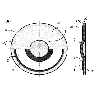
Fig. 2 shows schematic views of a part of the vibratable head
1 of the aerosol generator 2 of the aerosol delivery device
100 shown in Fig. 1. Fig. 2(a) shows a plan view of the part
of the vibratable head 1. Fig. 2(b) shows a schematic cross-
sectional view of the part of the vibratable head 1. In the
upper parts of Figs. 2(a) and (b), the vibrator 8 and the
adhesive 9 have been omitted and, in the lower part of Fig.
2(b), a roughened surface portion 10 has been omitted for
better presentability. The same form of presentation has also
been used in Figs. 3 to 9.
As is indicated by a hatched area in the upper part of Fig.
2(a) and by a solid line in the upper part of Fig. 2(b), the
support member 4 of the vibratable head 1 comprises an
annular surface portion 10 which has been roughened by laser
structuring. In the radially inward direction of the support
member 4, the roughened surface portion 10 extends to the
peripheral edge of the vibratable membrane 6. In the radially
outward direction of the support member 4, the roughened
surface portion 10 stops before the peripheral edge of the
ok 02994491 2010-02-01
W02017/021441 PCT/EP2016/068523
28
support member 4, leaving an annular non-roughened surface
portion 12 at the circumference of the support member 4.
The adhesive 9 is applied to the entire roughened surface
portion 10 of the support member 4 (see the lower part of
Fig. 2(a)), thus reliably preventing corrosion or oxidation
of this surface portion 10. As is schematically shown in Figs
2(a) and (b), an area of an attachment surface of the
vibrator 8, over which the vibrator 8 is attached to the
roughened surface portion 10 by a portion of the adhesive 9,
is smaller than the area of the roughened surface portion 10,
thus providing the benefit of manufacturing tolerances.
Fig. 3 shows schematic views of a part of a vibratable head
according to another embodiment of the present invention. In
Fig. 3, like elements are designated with like reference
signs as in Fig. 2.
The vibratable head according to the embodiment shown in Fig.
3 differs from the vibratable head 1 according to the
embodiment shown in Fig. 2 in that the roughened surface
portion 10 of the support member 4 extends in the radially
outward direction of the support member 4 to the peripheral
edge of the support member 4, as is schematically shown in
Fig. 3(a) and the upper part of Fig. 3(b).
Fig. 4 shows schematic views of a part of a vibratable head
according to another embodiment of the present invention. In
Fig. 4, like elements are designated with like reference
signs as in Figs. 2 and 3.
The vibratable head according to the embodiment shown in Fig.
4 differs from the vibratable head 1 according to the
embodiment shown in Fig. 2 in that, in the radially inward
direction of the support member 4, the roughened surface
portion 10 does not extend to the peripheral edge of the
membrane 6, leaving an annular non-roughened surface portion
ok 02994491 2018-02-01
WO 2017/021441 PCT/EP2016/068523
29
14 around the circumference of the membrane 6. In this way,
it can be ensured in a particularly reliable manner that the
roughening of the surface portion 10 does not affect the
oscillatory behaviour or vibrating characteristics of the
membrane 6. As is schematically shown in the lower parts of
Figs. 4(a) and (b), the adhesive 9 is applied over a surface
area of the support member 4 which extends beyond the
roughened surface portion 10 in the radially outward and
radially inward directions of the support member 4.
Fig. 5 shows schematic views of a part of a vibratable head
according to another embodiment of the present invention. In
Fig. 5, like elements are designated with like reference
signs as in Figs. 2 to 4.
The vibratable head according to the embodiment shown in Fig.
differs from the vibratable head 1 according to the
embodiment shown in Fig. 2 in that the vibratable membrane 6
is not formed integrally with the support member 4 but
attached thereto at an annular connection portion 16. The
vibratable membrane 6 may be attached to the support member 4
at the connection portion 16, for example, by welding,
soldering or the like.
Alternatively, the surface portion of the support member 4 at
which the membrane 6 is attached thereto may be partially or
entirely roughened by laser structuring and the membrane 6
may be attached to the support member 4 at the connection
portion 16 by an adhesive, substantially in the same way as
the vibrator 8 is attached to the roughened surface portion
of the support member 4.
The membrane 6 has a convex portion 20 and an annular, flat
peripheral portion 21 integrally formed with and surrounding
the convex portion 20. The peripheral portion 21 of the
membrane 6 is attached to the support member 4 at the
connection portion 16.
ok 02994491 2010-02-01
WO 2017/021441 PCT/EP2016/068523
As is schematically shown in Fig. 5(a) and the upper part of
Fig. 5(b) , the roughened surface portion 10 extends to the
peripheral edge of the peripheral portion 21 of the membrane
6 in the radially inward direction of the support member 4,
but stops before the peripheral edge of the support member 4
in the radially outward direction of the support member 4,
leaving the annular non-roughened surface portion 12 at the
circumference of the support member 4.
As is schematically shown in the lower parts of Figs. 5(a)
and (b), the adhesive 9 is applied over a surface area of the
support member 4 which extends beyond the roughened surface
portion 10 in the radially outward direction of the support
member 4 but stops before the peripheral edge of the
peripheral portion 21 of the membrane 6 in the radially
inward direction of the support member 4.
Fig. 6 shows schematic views of a part of a vibratable head
according to another embodiment of the present invention. In
Fig. 6, like elements are designated with like numerals as in
Figs. 2 to 5.
The vibratable head according to the embodiment shown in Fig.
6 differs from the vibratable head according to the
embodiment shown in Fig. 5 in that the roughened surface
portion 10 of the support member 4 does not extend to the
peripheral edge of the peripheral portion 21 of the
vibratable membrane 6 in the radially inward direction of the
support member 4, leaving the annular non-roughened surface
portion 14 along the outer circumference of the membrane 6.
In this way, it can be ensured in a particularly reliable
manner that the oscillatory behaviour or vibration
characteristics of the vibratable membrane 6 are not affected
by the roughening of the surface portion 10.
ok 02994491 2018-02-01
W02017/021441 PCT/EP2016/068523
31
As is schematically shown in the lower parts of Figs. 6(a)
and (b), the adhesive 9 is applied over a surface area of the
support member 4 which stops before the outer peripheral edge
of the roughened surface portion 10 in the radially outward
direction of the support member 4 and the inner peripheral
edge of the roughened surface portion 10 in the radially
inward direction of the support member 4.
Fig. 7 shows schematic views of a part of a vibratable head
according to another embodiment of the present invention. In
Fig. 7, like elements are designated with like numerals as in
Figs. 2 to 6.
The vibratable head according to the embodiment shown in Fig.
7 differs from the vibratable head according to the
embodiment shown in Fig. 5 in that the roughened surface
portion 10 of the support member 4 extends to the peripheral
edge of the support member 4 in the radially outward
direction of the support member 4.
As is schematically shown in the lower parts of Figs. 7(a)
and (b), the adhesive 9 is applied over a surface area of the
support member 4 which extends to the peripheral edge of the
peripheral portion 21 of the membrane 6 in the radially
inward direction of the support member 4 but stops before the
peripheral edge of the support member 4 in the radially
outward direction of the support member 4.
Fig. 8 shows schematic views of a part of a vibratable head
according to another embodiment of the present invention. In
Fig. 8, like elements are designated with like reference
signs as in Figs. 2 to 7.
The vibratable head according to the embodiment shown in Fig.
8 differs from the vibratable head according to the
embodiment shown in Fig. 7 in that a peripheral surface
portion 17 of the vibratable membrane 6, i.e., of the
m 02994491 2019-02-01
WO 2017/021441 PCT/EP2016/068523
32
peripheral portion 21 thereof, is roughened by laser
structuring.
The roughened surface portion 17 extends in the radially
inward direction of the membrane 6 to the peripheral edge of
the convex portion 20 of the membrane 6 and in the radially
outward direction of the membrane 6 to the peripheral edge of
the peripheral portion 21 of the membrane 6.
The adhesive 9 is applied to the roughened surface portion 17
of the vibratable membrane 6. The adhesive is applied to the
roughened surface portions 10, 17 so as to extend over a step
18 formed between the membrane 6 and the support member 4, as
is schematically shown in the lower part of Fig. 8(b). In the
radially outward direction of the support member 4, the
surface area of the support member 4 over which the adhesive
9 is applied stops before the peripheral edge of the support
member 4.
By applying the adhesive to the roughened surface portion 10
of the support member 4 and the roughened surface portion 17
of the vibratable membrane 6 in this way, the step 18 formed
between membrane 6 and support member 4 is reliably sealed,
thus particularly efficiently preventing corrosion or
oxidation of the membrane 6 and/or the support member 4 at
the connection portion 16.
Fig. 9 shows schematic views of a part of a vibratable head
according to another embodiment of the present invention. In
Fig. 9, like elements are designated with like reference
signs as in Figs. 2 to 8.
The vibratable head according to the embodiment shown in Fig.
9 differs from the vibratable head according to the
embodiment shown in Fig. 8 in that the roughened surface
portion 17 of the vibratable membrane 6 does not extend to
the peripheral edge of the convex portion 20 of the membrane
CA 02994491 2018-02-01
WO 2017/021441 PCT/EP2016/068523
33
6 in the radially inward direction of the membrane 6, leaving
an annular non-roughened surface portion 22 along the
circumference of the convex portion 20.
The adhesive 9 is applied to the roughened surface portions
10, 17, thereby sealing the step 18 between the vibratable
membrane 6 and the support member 4. By leaving the annular
non-roughened surface portion 22 at the circumference of the
convex portion 20, it can be particularly reliably ensured
that the oscillatory behaviour or the vibrating
characteristics of the vibratable membrane 6 are not affected
by the roughening of the surface portion 17.
As is schematically shown in the lower parts of Figs. 9(a)
and (b), the adhesive 9 is applied over a surface area of the
support member 4 which extends to the peripheral edge of the
convex portion 20 of the membrane 6 in the radially inward
direction of the support member 4 but stops before the
peripheral edge of the support member 4 in the radially
outward direction of the support member 4.
In the following, measurements performed on surface portions
of different support members which had been roughened using
different laser structuring processes will be discussed. In
particular, in these laser structuring processes, the
processing speed, i.e., the speed with which the support
member and the laser beam were moved relative to each other,
was varied, resulting in variations of the roughness of the
roughened surface portion. Moreover, for the surface portions
which had been roughened at the same processing speed,
variations in the average surface roughness Rz and the
roughness average Ra were achieved by varying further process
parameters, namely the laser power, the laser focus position,
the laser pulse frequency and the number of laser passes. The
surface profiles of the roughened surface portions were
measured using a Perthometer with a diamond tip and an
inductive transducer. The Perthometer was moved over the
CA 02994491 2018-1
WO 2017/021441 PCT/EP2016/068523
34
surface portion to be measured, allowing the diamond tip to
follow the surface roughness, and the resulting vertical
displacement of the diamond tip was converted into an
electrical signal.
The average surface roughnesses Rz and roughness averages Ra
in Am and the processing speed modes for the different
roughened surface portions are given in Table 1 below. The
processing speeds of modes 1 to 3 are in the range from SOO
mmis to 10,000 mm/s. The processing speed of mode 1 is
higher than the processing speed of mode 2 and the processing
speed of mode 2 is higher than the processing speed of mode
3.
Processing Speed Average Surface Roughness Average
(mode number] Roughness Rz fund Ra fuml
1 9.51 1.85
1 8.78 1.77
1 9.54 .1.52
2 10.14 2.07
.2 19.71 2.50
2 11.56 2.07
3 13.35 2.05
3 ,11.98 2.26
3 9.77 2.12
Table 1
Adhesive was applied to the above roughened surface portions
and the durability of the joint formed between the adhesive
and the roughened surface portion was determined.
The solidity and durability of the adhesive on the laser
structured substrate was tested by simulating a stress test.
The stress test indicates the maximal reliability of the
adhesive bonding.
CA 02994491 2018-02-01
W02017/021441 PCT/EP2016/068523
A simulated use test was performed, in which the use of the
vibratable head by a patient was simulated under
substantially realistic conditions. The test was carried out
by performing a repeated sequence of nebulisation, cleaning
and thermal disinfection in the same manner as in normal
operation. The stress test also included using an autoclave
for thermal disinfection/sterilisation up to 50 cycles. For
example, an autoclave of the company Systec can be used for
this purpose, e.g., Autoklav 3850 EL.
As a further test, a frequency band analysis was performed to
analyse the vibratable head of the aerosol generator.
Especially, an impedance measurement of the vibratable head
was performed. The analysis or measurement of the
vibrational spectrum may show a shift in resonance pattern of
the vibratable head that can indicate invisible changes of
the quality of the adhesive bonding. In the normal case, the
resonance frequency of the vibratable head is within the
specified range.
An additional test regarding the aerosol performance of the
vibratable head, such as aerosol output rate, particle size
distribution (MMD, GSD), was performed to ensure the correct
and specified performance characteristics of the vibratable
head in the aerosol generator.
It was found that a particularly high durability of the
adhesive joint was achieved for roughened surface portions
having an average surface roughness Rz in the range from 5.0
to 18.0 m and a roughness average R, in the range from 0.5
to 3.0 m. Particularly durable adhesive joints were
obtained by laser structuring with an adequate processing
speed, for example mode number 3 (Table 1).
Measurement profiles for the roughened surface portions shown
in Table 1 above which were provided with laser structuring
at an adequate processing speed are shown in Fig. 10. As has
ok 02994491 2018-02-01
W02017/021441 PCT/EP2016/068523
36
been detailed above, these profiles were measured using a
Perthometer with a diamond tip and an inductive transducer.
As can be seen from the surface profiles shown in Fig. 10,
roughened surfaces with an ordered roughness can be created
by laser structuring.
Fig. 11 shows SEM images of four different roughened surface
portions of support members of vibratable heads according to
embodiments of the present invention. The surface portions
shown in Fig. 11 were roughened by laser structuring with an
adequate processing speed, an adequate laser power and an
adequate laser pulse frequency. For the surface portions
shown in Figs. 11(a), (c) and (d), the laser was applied in a
first pattern, while for the surface portion shown in Fig.
11(b), the laser was applied in a second pattern. The laser
structuring processes employed for roughening the surface
portions shown in Figs. 11(a), (c) and (d) differ in the
number of laser pulses, which is medium for Fig. 11 (a), high
for Fig. 11 (c) and low for Fig. 11 (d). The number of laser
pulses for the surface portion shown in Fig. 11 (b) is
medium. As is evident from Fig. 11, varying the number of
laser pulses and/or the laser structuring pattern allows for
the resulting surface profile to be varied in a controlled
manner.
Alternatively or additionally, the processing speed and/or
the laser power and/or the laser pulse frequency may be
varied to create different laser structuring patterns.
The foregoing embodiments and their variants have been
disclosed for illustrative purposes only, and further
variation is wholly possible within the capabilities of the
skilled reader. Accordingly, the appended claims are intended
to cover all modifications, substitutions, alterations,
omissions and additions which one skilled in the art could
CA 02994491 2018-02-01
WO 2017/021441
PCT/EP2016/068523
37
achieve from the foregoing disclosure, taking into account
his own general and specialist knowledge and expertise.