Note: Descriptions are shown in the official language in which they were submitted.
LATCH FOR A CABINET
Field of Invention
[0001] The present invention relates to a latch for a cabinet.
Summary
[0002] A latch for a cabinet is described. The latch may be used to
secure a door
of the cabinet in a closed position. The door hingedly connects to a frame of
the cabinet. The
door may include sliding panels to cover an opening of the cabinet. A
combination hinged door
with the sliding panels may be used to cover the opening of the cabinet. This
type of hinged
door is commonly called a restocking closure.
[0003] The latch for the cabinet is well suited for use in cabinets
on emergency
vehicles, such as ambulance, fire trucks, etc. The cabinets may be used for
storage on such
vehicles. The door may be used to close the cabinets and prevent the contents
of the cabinet
from falling out of the cabinet. The latch secures the door in a closed
position over the cabinet.
[0004] The latch for the cabinet may be used with the restocking
closures, which
includes a hinged cabinet door with built-in sliding closures. This allows for
the cabinet to be
completely opened for restocking the cabinet, and also allows the cabinet to
be accessed by
sliding the closures, such as Plexiglas panels, to an open position for
immediately retrieval of
items from the cabinet.
[0005] The latch for the cabinet includes a handle that may be
accessed from an
exterior of the cabinet. The handle releases the latch such that the hinged
cabinet door may be
opened. There is no need for the operator to reach into the cabinet or through
the door in order
to release the latch. In a latched position, i.e., the hinged cabinet door is
closed and latched, the
handle is positioned outside of the cabinet. For example, in the latched
position, the handle is
positioned in front of a lower wall of the cabinet and below a lower edge of
the door.
[0006] In one aspect, a latch for a cabinet is described. The latch
includes a pawl
member that pivots or rotates relative to a pivot plate. The pawl member
includes a pawl tip
1
CA 2994614 2018-02-16
generally opposite of a pawl fulcrum end. The latch includes a striker. The
pawl member
engages and disengages with the striker. The latch includes a handle that is
configured to move.
The handle includes an upper end. The upper end is configured to contact the
pawl lever end to
cause the pawl member to pivot or rotate relative to the pivot plate to
disengage the pawl
member from the striker. The handle, pivot plate, and pawl member are
installed on a door of
the cabinet, while the striker is installed on the cabinet. The latch holds
the door in a locking or
latching engagement with the cabinet to maintain the door in the closed
position. A user may
press or squeeze on the handle causing the upper end of the handle to press
against the pawl lever
end, which releases the pawl member from the striker.
[0007] In another aspect, a latch for a cabinet is described. The
latch includes a
pawl member that pivots relative to a base member. The pawl member includes a
pawl tip
generally opposite of a pawl lever end. A handle member is configured to move.
The handle
member includes an upper end. The upper end is configured to contact the pawl
lever end to
cause the pawl member to pivot relative to the base member and to lower the
pawl tip. The pawl
member and the base member are engaged to the cabinet. A door is hingedly
connected to the
cabinet. The handle member is engaged to the door. The pawl tip is configured
to secure into a
groove of the door.
[0008] In another aspect, a latch for a cabinet is described. The
latch includes a
pawl member that pivots relative to a base member. The pawl member includes a
pawl tip
generally opposite of a pawl lever end. The pawl member includes a lower
surface. The pawl
member includes a pawl axle positioned between the pawl tip and the pawl lever
end. A handle
member includes an upper end. The upper end is linked to the pawl lever end to
drive the pawl
member. The handle, the pawl member, and the base member are engaged, linked
or attached to
a lower wall of the cabinet, and the pawl tip is configured to secure into a
groove of the door.
Brief Description of Drawings
[0009] FIG. 1 is a perspective view of the door engaged to the
cabinet via a hinge.
[0010] FIG. 2 is a perspective view of the door engaged to the
cabinet via the
hinge with the door in an open position.
2
CA 2994614 2018-02-16
[0011] FIG. 3A is a view of the first latch in a latched position.
[0012] FIG. 3B is a view of the first latch releasing from the
latched position.
[0013] FIG. 3C is a view of the first latch in an open position.
[0014] FIG. 4 is an exploded view of the first latch.
[0015] FIG. 5A is a view of the second latch in a latched position.
[0016] FIG. 5B is a view of the second latch releasing from the
latched position.
[0017] FIG. 5C is a view of the second latch in an open position.
[0018] FIG. 6 is an exploded view of the second latch.
[0019] FIG. 7 is a view of the third latch in a latched position.
[0020] FIG. 8A is a view of the third latch in a latched position.
[0021] FIG. 8B is a view of the third latch releasing from the
latched position.
[0022] FIG. 8C is a view of the third latch in an open position.
[0023] FIG. 9 is an exploded view of the third latch.
Detailed Description of Invention
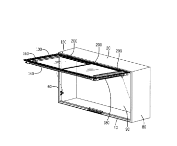
[0024] With reference to FIGS. 1 and 2, a cabinet 10 and a door 100
are shown.
The door 100 hingedly engages to a front of the cabinet 10 via a hinge 200.
One or more hinges
200 may hingedly connect the door 100 to the cabinet 10.
[0025] The cabinet includes an upper wall 20 opposite of a lower
wall 40 and a
left side wall 60 opposite of a right side wall 80. The walls 20, 40, 60, and
80 may be fastened
together with or without a rear wall 90. The door 100 may include conventional
construction or
may be formed from multiple frame sections, like the door 100. The door 100
includes an upper
frame section 120 opposite of a lower frame section 140 and a left frame
section 160 opposite of
a right frame section 180. The cabinet 10 may be formed to have a generally
rectangular or
square shape. One or more gas-springs may be incorporated between the cabinet
10 and the door
100 to control the opening and closing of the frame 100.
3
CA 2994614 2018-02-16
[0026] The hinge 200 includes a central portion, a first lateral
portion, and a
second lateral portion. The first and second lateral portions engage to the
cabinet 10. The
central portion engages to the door 100. The hinge 200 provides for the door
100 to move
between open and closed positions. The door 100 includes multiple sliding
panels to further
open and close access to the cabinet 10.
[0027] A first latch 300 will now be described with reference to
FIGS. 3-4. The
first latch 300 secures the door 100 in a closed position. The first latch 300
includes a pawl
member 310, a base member 340, and a handle 410. The pawl member 340 pivots
relative to the
base member 340. The handle 410 slides or moves relative to the door 100. The
handle 410
contacts the pawl member 310 to move the pawl member 310 to an unlatched
position. The
handle 410 is movably engaged to the door 100, while the pawl member 310 and
the base
member 340 are engaged to the lower wall 40 of the cabinet 10.
[0028] In this aspect, the handle 410 completely disengages from
the pawl
member 310 when the door 100 is sufficiently opened from the cabinet 10. A
user may unlatch
the first latch 300 using a single hand that presses upward on the handle 410,
which releases the
pawl member 310. Then, the user may pull on the handle 410 to open the door
100 to the cabinet
10, as the handle 410 moves with the door 100.
[0029] The first latch 300 includes a decoupled design ¨ in that
the handle 410
becomes completely separated, removed, distanced, etc. from the pawl member
310 when the
first latch 300 is unlatched and the door 100 is opened. The handle 410 moves
with the door
100, while the pawl member 310 and the base member 340 remain engaged to the
cabinet 10.
The handle 410 may contact the pawl member 310 during a closing of the door
100, but the
handle 410 is not mechanically attached or integrated with the pawl member
310.
[0030] The pawl member 310 includes a pawl tip 312 generally
opposite of a
pawl lever end 315. The pawl member 310 includes a lower surface 321. The pawl
member 310
also includes a pawl axle 318 positioned between the pawl tip 312 and the pawl
lever end 315
and extending downward from the lower surface 321. The pawl member 310 rotates
upward and
downward with respect to the pawl axle 318. The pawl member 310 also includes
a locking lip
324 extending downward from the lower surface 321. As described below, the
locking lip 324
assists in holding the pawl member 310 to the base member 340.
4
CA 2994614 2018-02-16
[0031] The base member 340 engages to the lower wall 40 of the
cabinet 10 and
holds the pawl member 310 in a biased and pivoting engagement. Fasteners 347
affix the base
member 340 to the lower wall. The base member 340 includes springs 344 that
urge against the
lower surface 321 of the pawl member 310. The springs 344 bias the pawl tip
312 towards a
bottom of the door 100. The springs 344 urge the pawl tip 312 upwards to
lockingly engage to
the door 100.
[0032] The base member 340 includes one or more end blocks 370,
which house
the springs 343. The end blocks 370 may include cylindrical openings 371 to
contain the springs
343 and control their biasing force. In other aspects, the springs 343 may be
integrated or
attached directly to the base member 340. The ends blocks 370 also include a
rear surface 373,
which prevents over rotation and forward movement of the pawl member 310,
which together
prevent unhinging.
[0033] The base member 340 includes a bearing surface 343 that
receives the
pawl axle 318. The pawl axle 318 rotates relative to the bearing surface 343.
The base member
340 further includes a locking lip 346 that interacts with the locking lip 324
of the pawl member
310. In the aspect shown, the locking lip 324 of the pawl member 310 is
positioned between the
pawl lever end 325 and the pawl axle 318. When the pawl member 310 is
installed to the base
member 340, the locking lip 324 is forced past the locking lip 346, which snap-
fits the pawl axle
318 against the bearing surface 343 of the base member 340.
[0034] When the user desires to open the cabinet 10, the user must
unlatch the
first latch 300. The user pushes the handle 410 upward, which causes the pawl
member 310 to
move to the unlatched position. The door 100 may now be opened. When the user
pushes the
handle 410 upward, an upper end 415 of the handle 410 presses against the pawl
lever end 315,
which raises or lifts the pawl lever end 315. As the pawl lever end 315 is
raised or lifted, the
pawl tip 312 is simultaneously lowered and is eventually removed from a groove
142 of the
lower frame section 140 of the door 100. This unlatches the door 100 from the
cabinet 10. As
such, the door 100 may now be opened. The groove 142 may be formed as part of
the extrusion
used in making the lower frame section 140. The groove 142 is formed in a
lower surface 144 of
the lower frame section 140. In other aspects, the groove 142 or other
catches, openings,
receiving, parts, etc. may be formed in lower or bottom surfaces of standard
doors.
CA 2994614 2018-02-16
[0035] The handle 410 is movably engaged to the door 100 and moves
relative to
the door 100. In the aspect shown, the handle 410 is configured to move toward
a center of the
door 100. In the aspect shown, the handle 410 moves generally vertically. The
handle 40
includes a gripping region 420 generally opposite of the upper end 415 of the
handle 410. The
gripping region 420 transitions into a generally vertical portion 425 that
leads into the upper end
415. A retaining portion 430 extends from the vertical portion 425. An opening
435 is formed
between the retaining portion 430 and the vertical portion 425. The opening
435 receives a
flange portion 440 of the door 110. As the handle 410 moves upward or
downward, the opening
435 moves away from or over the flange portion 440. These structures assist in
guiding the
movement of the handle 410. The flange portion 440 and an inner surface 144 of
the lower
frame section 140 also forms a channel 146 that receives the retaining portion
430. These
structures also assist in guiding the movement of the handle 410.
[0036] As shown in FIG. 3C, the upper end 415 of the handle 410
includes a
flattened upper surface 424 and a lateral portion 426. The lateral portion 426
extends toward the
inner surface 144 of the lower frame section 140. As the handle 410 moves
upward and
downward, the lateral portion 426 may slide against the inner surface 144.
[0037] In order to latch the door 100 in the closed position, the
door 100 is moved
to the closed position. The lower surface 144 of the lower frame section 140
presses against an
upper surface 326 of the pawl tip 312 of the pawl member 310, which causes the
pawl tip 312 to
move downward and thus overcoming the biasing force from the springs 343. As
the door 100 is
further moved to the closed position, the pawl tip 312 will eventually seat
into the groove 142 of
the lower frame section 140 of the door 100 when the door 100 is sufficiently
closed. The force
from the springs 343 holds the pawl tip 312 in the groove 142.
[0038] The first latch 300 includes the handle 410 that may be
accessed from an
exterior of the cabinet 10. The handle 410 releases the first latch 300 such
that the door 100 may
be opened by hinging upward. There is no need for the operator to reach into
the cabinet 10 in
order to release the first latch 300. In a latched position, i.e., wherein the
door 100 is closed and
latched, the handle 410 is positioned outside of the cabinet 10. For example,
in the latched
position, the handle 410 is positioned in front of the lower wall 40 of the
cabinet 10. Portions of
the handle 410, including the gripping region 420 are positioned exterior to
the door 100 and the
6
CA 2994614 2018-02-16
cabinet 10. The gripping region 420 may protrude from a bottom, front surface
of the cabinet 10,
providing convenient access to the operator to release the first latch 300.
The gripping region
420 may extend beyond a front surface of the door 100 or its lower frame
section 140.
[0039] A second latch 500 will now be described with reference to
FIGS. 5-6.
The second latch 500 also secures the door 100 in a closed position. The
second latch 500
includes a pawl member 510, a base member 540, and a handle 610. The pawl
member 510
pivots relative to the base member 540. The handle 610 is linked to the pawl
member 510 and
moves or drives the pawl member 510 to cause the pivoting of the pawl member
510 relative to
the base member 540. The base member 540 is affixed or engaged to the lower
wall 40 of the
cabinet 10.
[0040] A user may unlatch the second latch 500 by pressings upward
on the
handle 610, which releases the pawl member 510. Then, the user may pull on the
door 100 to
open the door 100 to the cabinet 10. When the door 100 is opened, the handle
610, the pawl
member 510 and the base member 540 remain engaged, linked or otherwise
attached to the
cabinet 10. The handle 610 does not move with the door 100.
[0041] The pawl member 510 includes a pawl tip 512 generally
opposite of a
pawl lever end 515. The pawl lever end 515 forms a receiving portion 520 that
receives an upper
end 615 of the handle 610. The receiving portion 520 forms a socket or opening
that receives the
upper end 615. The upper end 615 may move or articulate within the receiving
portion 520.
The upper end 615 may drive the lever end 515 in an upward movement.
[0042] The pawl member 510 further includes a lower surface 521.
The pawl
member 510 also includes a pawl axle 518 positioned between the pawl tip 512
and the pawl
lever end 525 and extending downward from the lower surface 521. The pawl
member 510
rotates upward and downward with respect to the pawl axle 518. The lower
surface 521 further
includes a stop member 532 that prevents over-rotation of the pawl member 510.
The stop
member 532 is positioned between the pawl axle 518 and the lever end 515. The
pawl tip 512
may rotate upward, under the forces of the springs 543, until the stop member
532, which is
moving downwards, contacts an upper surface 542 of the base member 540.
[0043] The base member 540 engages to the lower wall 40 of the
cabinet 10 and
holds the pawl member 510 in a biased and pivoting engagement. The base member
540
7
CA 2994614 2018-02-16
includes the springs 543 that urge against the lower surface 521 of the pawl
member 510. The
springs 543 urge the pawl tip 512 upwards to lockingly engage the door 100.
[0044] The base member 540 includes a bearing surface 545 that
receives the
pawl axle 518. The pawl axle 518 rotates relative to the bearing surface 545.
[0045] When the user desires to open the cabinet 10, the user must
unlatch the
second latch 500. The user pushes the handle 610 upward, which causes the pawl
member 510
to move to the unlatched position. The door 100 may now be opened. When the
user pushes the
handle 610 upward, the upper end 615 of the handle 610 presses against the
pawl lever end 515,
which raises or lifts the pawl lever end 515. As the pawl end 515 is raised or
lifted, the pawl tip
512 is simultaneously lowered and is eventually removed from the groove 142 of
the lower
frame section 140 of the door 100. As such, the door 100 may now be opened.
The groove 142
may be formed as part of the extrusion used in making the lower frame section
140. The groove
142 is formed in the lower surface 144 of the lower frame section 140 of the
door 100.
[0046] The handle 610 includes a gripping region 620 generally
opposite of the
upper end 615 of the handle 610. The gripping region 620 transitions into a
generally vertical
portion 625 that leads into the upper end 615.
[0047] In order to latch the door 100 in the closed position, the
door 100 is moved
to a closed position. The lower surface 144 of the lower frame section 140
presses against an
upper surface 526 of the pawl tip 512 of the pawl member 510, which causes the
pawl tip 512 to
move downward and thus overcoming the force from the springs 543. The pawl tip
512 will seat
into the groove 142 of the lower frame section 140 of the door 100 when the
door 100 is
sufficiently closed. The force from the springs 543 holds the pawl tip 512 in
the groove 142.
[0048] The second latch 500 includes the handle 610 that may be
accessed from
an exterior of the cabinet 10. The handle 610 releases the second latch 500
such that the door
100 may be opened by hinging upward. There is no need for the operator to
reach into the
cabinet 10 in order to release the second latch 500. In both latched position
and unlatched
positions, the handle 610 is positioned outside of the cabinet 10. The handle
610 is positioned in
front of the lower wall 40 of the cabinet 10. Portions of the handle 610,
including the gripping
region 620 are positioned exterior to the door 100 and the cabinet 10. The
gripping region 620
may protrude from a bottom, front surface of the cabinet 10, providing
convenient access to the
8
CA 2994614 2018-02-16
operator to release the first latch 300. The gripping region 620 may extend
beyond a front
surface of the door 100 or its lower frame section 140.
[0049] A third latch 700 will now be described with reference to
FIGS. 7, 8A, 8B,
8C, and 9. The third latch 700 secures the door 100 in a closed position. The
third latch 700
includes a pawl member 710, a striker 740, a pivot plate 750, and a handle
810. The pivot plate
750 holds the pawl member 710 in a pivotal or rotatable engagement. The pawl
member 710 is
biased toward the striker 740. The pawl member 710 pivots or rotates relative
to the pivot plate
750 in order to engage with the striker 740. The handle 810 slides or moves
relative to the door
100 when the user presses or urges the handle 810 upward or toward a flange
portion 440 along a
lower edge of the door 100. The handle 810 contacts the pawl member 710 to
move the pawl
member 710 to an unlatched or disengaged position. The handle 810, the pawl
member 710, and
the pivot plate 750 are engaged to the door 100 and move with door 100 when
the door 100 is
opened, while the striker 740 is engaged to the lower wall 40 of the cabinet
10 in a fixed or
stationary position relative to the cabinet 10.
[0050] In this aspect, the pawl member 710 completely disengages
from the
striker 740 when the door 100 is sufficiently opened from the cabinet 10. A
user may unlatch the
third latch 700 using a single hand that presses upward on the handle 810,
which releases the
pawl member 710 from the striker 740. The pawl member 710 moves with the
opening of the
door 100. The striker 740 remains engaged to the cabinet 10. Then, the user
may pull on the
handle 810 or other portion of the door 100 to open the door 100 to the
cabinet 10, as the handle
810 moves with the door 100. When the user presses upward on the handle 810 to
release the
pawl member 710 from the striker 740, the pawl member 710 rotates or pivots
relative to the
pivot plate 750.
[0051] The pawl member 710 includes a pawl tip 712 generally
opposite of a
pawl fulcrum end 715. The pawl member 710 includes a catch portion 722 between
the pawl
tip 712 and the pawl fulcrum end 715. The pawl member 710 includes a lower
surface 724. The
pawl member 710 rotates upward and downward with respect to the pawl fulcrum
end 715. The
catch portion 722 also includes a locking lip 728 on the lower surface 724. As
described below,
the locking lip 728 assists in holding the pawl member 710 to the striker 740.
9
CA 2994614 2018-02-16
[0052] The striker 740 engages to the lower wall 40 of the cabinet
10. The pivot
plate 750 holds the pawl fulcrum end 715 in a pivoting or rotating engagement.
The pivot plate
750 defines a socket 752 to pivotally or rotatably hold the fulcrum end 715.
The socket 752
includes an opening 754 narrower in dimension than a remainder of the socket
752. During
assembly, the fulcrum end 715 is laterally inserted into the socket 752 with a
tapered portion 719
of the pawl member 710 passing through the opening 754. One or more springs
760 bias the
pawl member 710 to a latching position, i.e., in a downward direction toward
the striker 740. The
springs 760 urge against an upper surface 718 of the pawl member 710. The
springs 760 bias the
pawl tip 712 towards the lower wall 40 of the cabinet 10. Fasteners affix the
striker 740 to the
lower wall 40 of the cabinet 10. The striker 740 may be held or fastened to
the cabinet 10 by one
or more end blocks 780.
[0053] The pivot plate 750 affixes to the groove 142 in a lower
edge of the door
100. In the aspect shown, the pivot plate 750 snaps into the groove 142 in the
lower edge of the
door 100. The groove 142 may be formed as part of the extrusion used in making
the lower
frame section 140. The groove 142 is formed in a lower surface 144 of the
lower frame section
140. In other aspects, the groove 142 or other catches, openings, receiving,
parts, etc. may be
formed in lower or bottom surfaces of standard doors.
[0054] The pawl member 710 includes the catch portion 722. The
catch portion
may be formed from a curved or arched section in the pawl member 710. The
catch portion 722
includes a concave surface 749 that receives the striker 740. The concave
surface 749 guides the
pawl member 710 to engage its locking lip 728 with the locking tip 745 of the
striker 740. The
locking tip 745 of the striker 740 may be formed over a concave section 755 of
the striker 740.
The concave section 755 may receive the locking lip 728 of the pawl member
710. The concave
section 755 may include an opening 757 facing a rear of the cabinet 10.
[0055] When the user desires to open the cabinet 10, the user must
unlatch the
third latch 700. The user pushes the handle 810 upward, which causes the pawl
member 710 to
move to the unlatched position. The door 100 may now be opened. When the user
pushes the
handle 810 upward, the handle 810 presses against the pawl tip 712, which
raises or lifts the
pawl tip 712. As the pawl tip 712 is raised or lifted, the locking lip 728 of
the pawl member 710
CA 2994614 2018-02-16
is raised and disengaged from the locking tip 745 of the striker 740. This
unlatches the door 100
from the cabinet 10. As such, the door 100 may now be opened.
[0056] The locking tip 745 of the striker 740 and the locking lip
728 of the pawl
member 710 are formed with contacting surfaces at complementary reverse angles
that lockingly
engage one another. A force that merely pulls on the door 110 will not
normally disengage the
locking lip 728 of the pawl member 710 from the locking tip 745 of the striker
740. The
actuation of the handle 810 is generally needed to disengage the locking lip
728 of the pawl
member 710 from the striker 740. The actuation of the handle raises the pawl
tip 712 and also
slightly urges the pawl member in rearward direction, i.e., toward a rear of
the cabinet 10. This
releases the locking lip 728 of the pawl member 710 from the striker 740.
[0057] The handle 810 is movably engaged to the door 100. The
handle 810
moves toward a center of the door 100. In the aspect shown, the handle 810
moves generally
vertically. The handle 810 is biased downward by a spring 815, which may
include, for
example, one or more leaf springs, coils springs, or other biasing members. A
spring 815 may be
used on both a left side and a right side of the handle 810. The handle 810
includes a gripping
region 820 at a lower portion of the handle 810. When the user pushes the
handle 810 upward,
the spring 815 is compressed and the handle 810 presses against the pawl tip
712. When the user
releases the handle 810, the spring 815 biases the handle 810 downward and
away from the pawl
tip 712. The handle 810 is held by a channel 446 of the lower frame section
140 of the door
100. Retaining clips 816 hold the handle 810 to the channel 446 and prevent
lateral movement
of the handle 810.
[0058] The handle 810 includes an inner wall 830 and outer wall
860. The inner
wall 830 and the outer wall 860 are both generally vertical. The inner wall
830 and the outer
wall 860 define an interior space 865, which houses the spring 815. The inner
wall 830
transitions into a flattened upper surface 832 and a generally vertical inner
portion 834. An
opening 836 is formed between the inner wall 830 and the inner portion 834.
The opening 836
receives an upwardly extending portion 442 of the flange portion 440 of the
door 110. As the
handle 810 moves upward or downward, the opening 836 moves away from or toward
the
upwardly extending portion 442 of the flange portion 440. These structures
assist in guiding the
movement of the handle 810. The upwardly extending portion 442 of flange
portion 440 and an
11
CA 2994614 2018-02-16
inner surface 144 of the lower frame section 140 also forms the channel 446
that receives the
generally vertical inner portion 834. As the handle 810 moves upward and
downward, the
generally vertical inner portion 834 may enter and retract from the channel
446. Also, as the
handle 810 moves upward and downward, an end 833 of the flattened upper
surface 832 may
slide against an inner surface 147 of the door 110. These structures also
assist in guiding the
movement of the handle 810 relative to the flange portion 440 of the door 110.
[0059] The spring 815 is positioned in the interior space 865
between the inner
wall 830 and the outer wall 860. The spring 815 biases against a lower inner
surface 867 of the
handle 810 and a lower outer surface 444 of the flange portion 440 of the door
110.
[0060] As shown in FIG. 7, the inner wall 830 of the handle 810
transitions into
the flattened upper surface 832. The flattened upper surface 832 of the handle
810 is angled
downward towards the cabinet 10. As the flattened upper surface 832 moves
upward and
contacts the pawl tip 712, the flattened upper surface 832 raises the pawl tip
712, and, due to the
downward angle of the flattened upper surface 832, urges the pawl member 710
toward the rear
of the cabinet 10.
[0061] In order to latch the door 100 in the closed position, the
door 100 is moved
to the closed position. The pawl member 710 includes the lower surface 724. As
the door 100 is
closed, the lower surface 724 of the pawl member 710 presses against an upper
surface 744 of
the striker 740, which causes the pawl member 710 to rotate upward and
compress the springs
760. As the door 100 is further moved to the closed position, the upper
surface 744 of the striker
740 will seat into the catch portion 722, and the locking lip 728 of the pawl
member 710 will
engage with the locking tip 745 of the striker 740 when the door 100 is
sufficiently closed. The
force from the springs 760 holds the locking lip 728 of the pawl member 710
engaged with the
locking tip 745 of the striker 740. A lower surface 770 of the pivot plate 750
may include
cylindrical openings 781 to contain the springs 760 and control their biasing
force. In other
aspects, the springs 760 may be integrated or attached directly to the pivot
plate 750. The
springs 760 bias against the upper surface 718 of the pawl member 710.
[0062] The third latch 700 includes the handle 810 that may be
accessed from an
exterior of the cabinet 10. The handle 810 releases the third latch 700 such
that the door 100
may be opened by hinging upward. There is no need for the operator to reach
into the cabinet 10
12
CA 2994614 2018-02-16
in order to release the third latch 700. In a latched position, i.e., wherein
the door 100 is closed
and latched, the handle 810 is positioned outside of the cabinet 10. For
example, in the latched
position, the handle 810 is positioned in front of the lower wall 40 of the
cabinet 10. Portions of
the handle 810, including the gripping region 820 are positioned exterior to
the door 100 and the
cabinet 10. The gripping region 820 may protrude from a bottom, front surface
of the cabinet 10,
providing convenient access to the operator to release the third latch 700.
The gripping region
820 may extend beyond a front surface of the door 100 or its lower frame
section 140.
[0063] FIG. 8A is a view of the third latch 700 in a latched
position. The springs
760 biases the pawl member 710 to the latching position, i.e., in a downward
direction toward
the striker 740. The force from the springs 760 holds the locking lip 728 of
the pawl member
710 engaged with the locking tip 745 of the striker 740. Also, the spring 815
biases the handle
810 downward and away from the pawl tip 712. In the latched position, there is
a space or gap
between the flattened upper surface 832 of the handle 810 and the pawl tip
712. This
arrangement helps to provide confirmation or an indication that the locking
lip 728 of the pawl
member 710 is engaged with the locking tip 745 of the striker 740, as the user
may feel that the
handle 810 is not under a downward bias from the pawl tip 712 pressing against
the handle 810.
[0064] FIG. 8B is a view of the third latch 700 releasing from the
latched
position. The user has pushed the handle 810 upward, thus compressing the
spring 815 and
pressing the handle 810 against the pawl tip 712 to rotate the pawl member 710
upward and
disengage with the locking tip 745 of the striker 740.
[0065] FIG. 8C is a view of the third latch 700 and the door 100 in
an open
position. The user has released the handle 810. The spring 815 biases the
handle 810 downward
and away from the pawl tip 712. The biasing force from the springs 760 has
rotated the pawl
member 710 downward. When desired, the door 100 may be moved to the closed
position to
engage the locking lip 728 of the pawl member 710 with the locking tip 745 of
the striker 740.
[0066] The third latch 700 includes a decoupled design ¨ in that
the handle 810
and the pawl member 710 becomes completely separated, removed, distanced, etc.
from the
striker 740 when the third latch 700 is unlatched and the door 100 is opened.
The handle 810
and pawl member 710 move with the door 100, while the striker 740 remains
engaged to the
cabinet 10. The handle 810 and the pawl member 710 may contact the striker 740
during a
13
CA 2994614 2018-02-16
closing of the door 100, but the handle 810 is not mechanically attached or
integrated with the
striker 740.
[0067] As shown in FIG. 9, the pawl member 710 may include one or
more
sections. This provides flexibility when using the third latch 700 with
different sized doors 100.
Additional sections of the pawl member 710 may be used for lager doors 100 to
provide
additional security.
[0068] The third latch 700, and the other latches described herein,
may be used
with any of a variety of cabinets and doors. For example, the third latch 700
may be installed on
a cabinet and door in which the door swings down to open. In this arrangement,
the third latch
700 is installed along an upper edge of the door and cabinet. Gas springs or
other dampers may
be used to assist the opening of the door. In other examples, the third latch
700 may be installed
on a cabinet with a single door that swings out laterally, i.e., the door
swings to the left or to the
right. In this installation, the third latch 700 may be installed along an
upper or lower edge of the
door and cabinet with a hinge on the left or right side. In other examples,
the third latch 700
may be installed on a cabinet with double doors that swing out, i.e., one door
swings to the left
and the other door swings to the right. In this installation, the third latch
700 may be installed
along upper or lower edges of the door and cabinet with hinges on the left and
right sides.
[0069] As such, it should be understood that the disclosure is not
limited to the
particular aspects described herein, but that various changes and
modifications may be made
without departing from the spirit and scope of this novel concept as defined
by the following
claims. Further, many other advantages of applicant's disclosure will be
apparent to those
skilled in the art from the above descriptions and the claims below.
14
CA 2994614 2018-02-16