Note: Descriptions are shown in the official language in which they were submitted.
CA 02994806 2018-02-05
=
WO 2017/048245
PCT/US2015/050345
DUAL FREQUENCY ELEMENTS FOR WELLBORE
COMMUNICATIONS
TECHNICAL FIELD
The present disclosure generally relates to communications during downhole
operations and, more particularly, to dual frequency elements for wellbore
communications.
BACKGROUND
Natural resources such as gas, oil, and water residing in a subterranean
formation or
to zone are usually recovered by drilling a wellbore into the subterranean
formation while
circulating a drilling fluid in the wellbore. After terminating the
circulation of the drilling
fluid, a string of pipe (e.g., casing) is run in the wellbore. The drilling
fluid is then usually
circulated downward through the interior of the pipe and upward through an
annulus, which is
located between the exterior of the pipe and the walls of the wellbore. Next,
cementing is
is
typically performed whereby a cement slurry is placed in the annulus and
permitted to set into
a hard mass (i.e., sheath) to seal the annulus.
An ongoing need exists for methods and apparatus for monitoring wellbore
cementing
operation from placement through the service lifetime of cementing fluids.
Information about
conditions of cementing fluids along the casing may be communicated to a well
operator.
zo Hence, it is desirable to develop efficient elements (apparatus) for
communications.
BRIEF DESCRIPTION OF THE DRAWINGS
Various embodiments of the present disclosure will be understood more fully
from the
detailed description given below and from the accompanying drawings of various
25
embodiments of the disclosure. In the drawings, like reference numbers may
indicate
identical or functionally similar elements.
FIG. 1 is a cross-sectional view of an example of a well system that includes
a system
for determining characteristics of a fluid in a wellbore and/or in an annulus
between a casing
and a reservoir formation, according to certain embodiments of the present
disclosure.
30 FIG. 2
is a cross-sectional view of a casing with different implementations of nodes
along the casing, according to certain embodiments of the present disclosure.
1
= CA 02994806 2018-02-05
WO 2017/048245
PCT/US2015/050345
FIG. 3 is a flow chart of a method for multi-frequency communications,
according to
certain embodiments of the present disclosure.
FIG. 4 is a block diagram of an illustrative computer system in which
embodiments of
the present disclosure may be implemented.
DETAILED DESCRIPTION
Embodiments of the present disclosure relate to multi-frequency elements for
communications during wellbore operations. While the present disclosure is
described herein
with reference to illustrative embodiments for particular applications, it
should be understood
that embodiments are not limited thereto. Other embodiments are possible, and
modifications
can be made to the embodiments within the spirit and scope of the teachings
herein and
additional fields in which the embodiments would be of significant utility.
In the detailed description herein, references to "one embodiment," "an
embodiment,"
"an example embodiment," etc., indicate that the embodiment described may
include a
is particular feature, structure, or characteristic, but every
embodiment may not necessarily
include the particular feature, structure, or characteristic. Moreover, such
phrases are not
necessarily referring to the same embodiment. Further, when a particular
feature, structure, or
characteristic is described in connection with an embodiment, it is submitted
that it is within
the knowledge of one skilled in the art to implement such feature, structure,
or characteristic
in connection with other embodiments whether or not explicitly described. It
would also be
apparent to one skilled in the relevant art that the embodiments, as described
herein, can be
implemented in many different embodiments of software, hardware, firmware,
and/or the
entities illustrated in the figures. Any actual software code with the
specialized control of
hardware to implement embodiments is not limiting of the detailed description.
Thus, the
operational behavior of embodiments will be described with the understanding
that
modifications and variations of the embodiments are possible, given the level
of detail
presented herein.
The disclosure may repeat reference numerals and/or letters in the various
examples or
Figures. This repetition is for the purpose of simplicity and clarity and does
not in itself
dictate a relationship between the various embodiments and/or configurations
discussed.
Further, spatially relative terms, such as beneath, below, lower, above,
upper, uphole,
downhole, upstream, downstream, and the like, may be used herein for ease of
description to
2
= CA 02994806 2018-02-05
WO 2017/048245
PCT/US2015/050345
describe one element or feature's relationship to another element(s) or
feature(s) as
illustrated, the upward direction being toward the top of the corresponding
figure and the
downward direction being toward the bottom of the corresponding figure, the
uphole
direction being toward the surface of the wellbore, the downhole direction
being toward the
toe of the wellbore. Unless otherwise stated, the spatially relative terms are
intended to
encompass different orientations of the apparatus in use or operation in
addition to the
orientation depicted in the Figures. For example, if an apparatus in the
Figures is turned over,
elements described as being "below" or "beneath" other elements or features
would then be
oriented "above" the other elements or features. Thus, the exemplary term
"below" can
io encompass both an orientation of above and below. The apparatus may be
otherwise oriented
(rotated 90 degrees or at other orientations) and the spatially relative
descriptors used herein
may likewise be interpreted accordingly.
Moreover even though a Figure may depict a horizontal wellbore or a vertical
wellbore, unless indicated otherwise, it should be understood by those skilled
in the art that
the apparatus according to the present disclosure is equally well suited for
use in wellbores
having other orientations including vertical wellbores, slanted wellbores,
multilateral
wellbores or the like. Likewise, unless otherwise noted, even though a Figure
may depict an
offshore operation, it should be understood by those skilled in the art that
the apparatus
according to the present disclosure is equally well suited for use in onshore
operations and
2o vice-versa. Further, unless otherwise noted, even though a Figure may
depict a cased hole, it
should be understood by those skilled in the art that the apparatus according
to the present
disclosure is equally well suited for use in open hole operations.
Illustrative embodiments and related methods of the present disclosure are
described
below in reference to FIGS. 1-4 as they might be employed for multi-frequency
communications in wellbore operations, such as during and/or after a cementing
operation. In
the interest of clarity, not all features of an actual implementation or
method are described in
this specification. It will of course be appreciated that in the development
of any such actual
embodiment, numerous implementation-specific decisions must be made to achieve
the
developers' specific goals, such as compliance with system-related and
business-related
constraints, which will vary from one implementation to another. Moreover, it
will be
appreciated that such a development effort might be complex and time-
consuming, but would
nevertheless be a routine undertaking for those of ordinary skill in the art
having the benefit
3
= = CA 02994806 2018-02-05
WO 2017/048245
PCT/US2015/050345
of this disclosure. Further aspects and advantages of the various embodiments
and related
methods of the disclosure will become apparent from consideration of the
following
description and drawings.
FIG. 1 is a cross-sectional view of an example of a well system 100 that
includes a
system for determining characteristics of a fluid in a wellbore and/or in an
annulus between a
casing and a reservoir formation, according to certain embodiments of the
present disclosure.
The well system 100 includes a wellbore 102 extending through various earth
strata. The
wellbore 102 extends through a hydrocarbon bearing subterranean formation 104.
A casing
string 106 extends from the surface 108 to the subterranean formation 104. The
casing string
io 106 can provide a conduit through which fluid 122, such as production
fluids produced from
the subterranean formation 104, can travel from the wellbore 102 to the
surface 108. The
casing string 106 can be coupled to the walls of the wellbore 102. For
example, one or more
fluids 105 (e.g., cementing fluids) can be pumped (e.g., using pumping
equipment or a pump)
in an annulus 107 between the casing string 106 and the walls of the wellbore
102 for
coupling the casing string 106 to the wellbore 102. In one or more
embodiments, fluid 105
pumped into the annulus 107 may be a cement slurry. Mixing equipment (not
shown) may be
utilized for mixing fluids and forming the cement slurry 105.
The well system 100 can also include at least one well tool 114 (e.g., a
formation-
testing tool). The well tool 114 can be coupled to a wireline 110, slickline,
or coiled tube that
zo can be deployed into the wellbore 102. The wireline 110, slickline, or
coiled tube can be
guided into the wellbore 102 using, for example, a guide 112 or winch. In some
examples,
the wireline 110, slickline, or coiled tube can be wound around a reel 116.
The well system 100 can include one or more nodes (sensors) 118 that may be
located
at discrete locations along the casing string 106 (e.g., external to the
casing string 106) in the
annulus region 107 of the wellbore 102. In one or more embodiments, the nodes
118 can
include a protective housing (e.g., a fluid resistant housing). This can
prevent the nodes 118
from being damaged by fluids 105, 122, the well tool 114, and/or debris
downhole.
For certain embodiments, a node 118 can include an inclinometer. The
inclinometer
can determine the inclination of the well system 100 (e.g., by detecting the
inclination of the
casing string 106 to which the sensor 118 can be coupled). This can be
particularly useful if
the well system 100 is an angled well system (e.g., the wellbore 102 is
drilled at an angle
between 0 and 90 degrees). Additionally or alternatively, a node 118 can
include a pH sensor.
4
= CA 02994806 2018-02-05
WO 2017/048245
PCT/US2015/050345
The pH sensor can determine the pH of one or more fluids 105, 122 in the
wellbore 102. In
some examples, the node 118 can additionally or alternatively include a
hydrocarbon sensor.
The hydrocarbon sensor can detect the presence of, or a characteristic of, a
hydrocarbon in the
wellbore 102.
For certain embodiments, the nodes 118 can be coupled external to the casing
string
106 in the annulus 107. This can allow the nodes 118 to monitor the
characteristics of the
well system 100, even if the well tool 114 is removed or changed. For example,
the node 118
can be positioned external to an outer housing of, or partially embedded
within, the casing
string 106. In one or more embodiments, the nodes 118 may be configured to
directly
io communicate with Radio Frequency (RF) Micro-Electro-Mechanical System
(MEMS) tags
placed in one or more fluids flowing through the annulus 107 along the casing
string 106
during the cementing operation. This can allow the nodes 118 to obtain
information where a
specific fluid is positioned along the casing string 106 in the annulus 107 at
any time (e.g.,
during and/or after the cementing operation), which is of crucial importance
for evaluating
quality of the cementing operation in the wellbore.
In one or more embodiments, the nodes 118 can transmit data (e.g., via wires
or
wirelessly) with information about the characteristics of the wellbore 102,
the fluids 105,
and/or the fluid 122 to a receiver 124 of the well tool 114. In one or more
other
embodiments, the nodes 118 can transmit data (e.g., via wires or wirelessly)
with information
zo about the characteristics of the wellbore 102, the fluids 105, and/or
the fluid 122 to a receiver
126 positioned on a surface 108. In one or more other embodiments, the nodes
118 can
transmit data (e.g., wirelessly) with information about the characteristics of
the wellbore 102,
the fluids 105, and/or the fluid 122 to one or more other nodes 118. The
information may be
then relayed from the receiving nodes 118 to the receiver 124 and/or the
receiver 126. In
some embodiments, the nodes 118 can transmit data using very low frequency
(VLF)
magnetic or current pulses, ultrasonic pulses, acoustic pulses,
electromagnetic coupling,
inductive coupling, or any combination of these.
One or more receivers 124, 126 can be positioned in the well system 100 for
receiving
data from the nodes 118. In some embodiments, the receivers 124, 126 can be
positioned on
the well tool 114, on the casing string 106, or at the surface 108 of the well
system 100. The
receivers 124, 126 can directly or indirectly receive the data from the nodes
118. For
example, a receiver 124 can wirelessly receive data from a node 118. The
receiver 124 can
5
= = CA 02994806 2018-02-05
WO 2017/048245
PCT/US2015/050345
then relay the data via wireline 110 to another receiver 126 at the surface
108. In some
embodiments, the receiver 124 can include a distributed acoustic sensor (DAS).
A DAS can
include a fiber-optic device configured to detect acoustic transmissions
(e.g., acoustic
emissions) from the nodes 118. In some embodiments, the receiver 124 can use
the DAS to
receive (e.g., detect) acoustic transmissions from the node 118.
It may be desirable in wellbore applications to utilize substantially
different
frequencies in communications, for example, for long and short range
communications.
Embodiments of the present disclosure are directed to utilizing dual frequency
nodes (or more
generally, nodes having a plurality of frequency ranges) for communication of
wellbore-
io related information. In one or more embodiments, nodes configured for multi-
frequency
communications may be the nodes 118 of the well system 100 from FIG. 1,
wherein the
multi-frequency nodes are located externally along the casing string 106 in
the annulus 107 of
the wellbore 102.
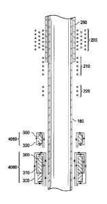
FIG. 2 illustrates a cross-sectional view of a casing 150 with different
is implementations of nodes along a casing core, according to certain
embodiments of the
present disclosure. The casing 150 illustrated in FIG. 2 may correspond to the
casing string
106 illustrated in FIG. 1. As illustrated in FIG.2, nodes along the casing may
comprise
wirings 200 that may be wrapped around a sensor core 250. In one or more
embodiments,
some of the wirings 200 may comprise a first number of turns around the sensor
core 250,
20 and some other of the wirings 200 may comprise a second number of turns
around the sensor
core 250, wherein the first number of turns is different than the second
number of turns. A
node comprising fewer turns may operate at a higher resonant frequency having
a shorter
propagation range. Although having a shorter propagation range, this node may
be
characterized with a higher bandwidth, where more information can be
communicated to
zs other nodes (receivers) for a certain time period (i.e., a communication
throughput is higher).
In contrast, another node located along the casing comprising more wiring
turns may operate
at a lower resonant frequency having a longer propagation range. However, this
node may be
characterized with a smaller bandwidth, where fewer information can be
communicated to
other nodes (receivers) for a certain time period (i.e., communication
throughput is smaller).
30 For
certain embodiments, a plurality of nodes located along the casing 150 may
communicate with each other and other receivers (e.g., the receivers 124 and
126 of the well
system 100 illustrated in FIG. 1). In one or more embodiments, data
communicated among
6
= CA 02994806 2018-02-05
WO 2017/048245
PCT/US2015/050345
the nodes may comprise information where a specific fluid is positioned along
the casing 150
at any time (e.g., during and/or after cementing operation), which can be of
crucial
importance for evaluating quality of the cementing operation in a wellbore. In
an
embodiment of the present disclosure, the information about the fluid
positions may be
provided to the nodes along the casing 150 from RF MEMS tags placed in fluids
flowing
along the casing 150 in an annulus region of a wellbore during the cementing
operation.
In one or more embodiments, a set of nodes along the casing 150 adjacent to
each
other may simultaneously communicate with at least one receiving node (e.g.,
receiver 124
and/or receiver 126 from FIG. 1, or one or more other nodes located along the
casing 150
io illustrated in FIG. 2). Each node from the set of adjacent nodes may be
designed and
configured to utilize a different resonant frequency for communication. In an
embodiment,
each resonant frequency may be located in a high frequency spectrum, which may
facilitate
achieving a larger information bandwidth (i.e., more information may be
communicated
within a predetermined time period). In addition, signals transmitted from the
adjacent nodes
may have non-overlapping bandwidths (e.g., bandwidths separated by a
predetennined guard
interval). In this way, interference between signals transmitted from
different adjacent nodes
can be substantially mitigated, i.e., more reliable communication may be
achieved during
wellbore operations.
As further illustrated in FIG. 2, in one or more embodiments, a node located
along the
casing 150 may comprise a set of wirings 210 that are wholly or partially
placed on the same
sensor core 250. Alternatively or additionally, a node located along the
casing 150 may
comprise a set of wirings 220 that are physically separated (e.g., by 1 cm to
lm, more
specifically, 10cm) from the sensor core 250.
For certain embodiments of the present disclosure, toroidally wound coils may
be
employed around the casing 150 for designing nodes capable of multi-frequency
communications. In one or more embodiments, as illustrated in FIG. 2, node
units 4050 and
4060 may be physically separated and utilize different core materials 350 and
360. For
example, node 320 may use core material 350 and node 300 may use core material
360. In
one or more other embodiments, core materials of different nodes may be the
same. For
3o example, as illustrated in FIG. 2, nodes (coils) 300 and 310 may utilize
the same core 360.
Discussion of an illustrative method of the present disclosure will now be
made with
reference to FIG. 3, which is a flow chart 30 of a method for multi-frequency
communications
7
CA 02994806 2018-02-05
WO 2017/048245
PCT/US2015/050345
in wellbore operations such as during and/or after cementing operation,
according to certain
embodiments of the present disclosure. The method begins at 32 by performing
data
communication simultaneously, or sequentially, involving a plurality of nodes
(e.g., nodes
118 from FIG. 1, nodes related to embodiments illustrated in FIG. 2) located
along a casing in
a wellbore (e.g., casing 106 of wellbore 102 from FIG. 1, casing 150
illustrated in FIG. 2),
and by using multiple frequencies for the data communication. At 34, one or
more operations
related to the wellbore (e.g., cementing operations related to an annulus
between the casing
and a reservoir formation of the wellbore) may be initiated based on the data
communicated
by the plurality of nodes located along the casing in the wellbore.
FIG. 4 is a block diagram of an illustrative computing system 400 in which
embodiments of the present disclosure may be implemented adapted for multi-
frequency
communications in wellbore operations such as during and/or after cementing
operation. For
example, some operations of method 30 of FIG. 3, as described above, may be
implemented
using the computing system 400. The computing system 400 can be a computer,
phone,
is personal digital assistant (PDA), or any other type of electronic
device. Such an electronic
device includes various types of computer readable media and interfaces for
various other
types of computer readable media. In one or more embodiments, the computing
system 400
may be an integral part of the receiver device 126 of the well system 100
illustrated in FIG. 1.
For example, the computing system 400 may be configured to receive from a
plurality of
.. nodes 118 (e.g., using multi-frequency communications) information related
to characteristics
of one or more fluids 105 located external to the casing string 106 in the
annulus 107 in the
vicinity of each of the plurality of nodes 118. The computing system 400 may
be further
configured to process the received information about fluid locations, provide
visual
information to a well operator about fluid locations along the casing during
and/or after the
z5 cementing operation, and initiate appropriate operation(s) related to
the wellbore 102 (e.g.,
one or more corrective cementing operations) based on the information about
locations of
fluids along the casing string 106.
As shown in FIG. 4, the computing system 400 includes a permanent storage
device
402, a system memory 404, an output device interface 406, a system
communications bus
3o 408, a read-only memory (ROM) 410, processing unit(s) 412, an input
device interface 414,
and a network interface 416. The bus 408 collectively represents all system,
peripheral, and
chipset buses that communicatively connect the numerous internal devices of
the computing
8
= CA 02994806 2018-02-05
WO 2017/048245
PCT/US2015/050345
system 400. For instance, the bus 408 communicatively connects the processing
unit(s) 412
with the ROM 410, the system memory 404, and the permanent storage device 402.
From these various memory units, the processing unit(s) 412 retrieves
instructions to
execute and data to process in order to execute the processes of the subject
disclosure. The
processing unit(s) can be a single processor or a multi-core processor in
different
implementations.
The ROM 410 stores static data and instructions that are needed by the
processing
unit(s) 412 and other modules of the computing system 400. The permanent
storage device
402, on the other hand, is a read-and-write memory device. This device is a
non-volatile
to memory unit that stores instructions and data even when the computing
system 400 is off.
Some implementations of the subject disclosure use a mass-storage device (such
as a
magnetic or optical disk and its corresponding disk drive) as the permanent
storage device
402.
Other implementations use a removable storage device (such as a floppy disk,
flash
drive, and its corresponding disk drive) as the permanent storage device 402.
Like the
permanent storage device 402, the system memory 404 is a read-and-write memory
device.
However, unlike the storage device 402, the system memory 404 is a volatile
read-and-write
memory, such a random access memory. The system memory 404 stores some of the
instructions and data that the processor needs at runtime. in some
implementations, the
processes of the subject disclosure are stored in the system memory 404, the
permanent
storage device 402, and/or the ROM 410. For example, the various memory units
include
instructions for computer aided pipe string design based on existing string
designs in
accordance with some implementations. From these various memory units, the
processing
unit(s) 412 retrieves instructions to execute and data to process in order to
execute the
processes of some implementations.
The bus 408 also connects to the input and output device interfaces 414 and
406. The
input device interface 414 enables the user to communicate information and
select commands
to the computing system 400. Input devices used with the input device
interface 414 include,
for example, alphanumeric, QWERTY, or T9 keyboards, microphones, and pointing
devices
(also called "cursor control devices"). The output device interfaces 406
enables, for example,
the display of images generated by the computing system 400. Output devices
used with the
output device interface 406 include, for example, printers and display
devices, such as
9
CA 02994806 2018-02-05
WO 2017/048245
PCT/US2015/050345
cathode ray tubes (CRT) or liquid crystal displays (LCD). Some implementations
include
devices such as a touchscreen that functions as both input and output devices.
It should be
appreciated that embodiments of the present disclosure may be implemented
using a
computer including any of various types of input and output devices for
enabling interaction
with a user. Such interaction may include feedback to or from the user in
different forms of
sensory feedback including, but not limited to, visual feedback, auditory
feedback, or tactile
feedback. Further, input from the user can be received in any form including,
but not limited
to, acoustic, speech, or tactile input. Additionally, interaction with the
user may include
transmitting and receiving different types of information, e.g., in the form
of documents, to
io and from the user via the above-described interfaces.
Also, as shown in FIG. 4, the bus 408 also couples the computing system 400 to
a
public or private network (not shown) or combination of networks through a
network
interface 416. Such a network may include, for example, a local area network
("LAN"), such
as an Intranet, or a wide area network ("WAN"), such as the Internet. Any or
all components
is of the computing system 400 can be used in conjunction with the subject
disclosure.
These functions described above can be implemented in digital electronic
circuitry, in
computer software, firmware or hardware. The techniques can be implemented
using one or
more computer program products. Programmable processors and computers can be
included
in or packaged as mobile devices. The processes and logic flows can be
performed by one or
zo more programmable processors and by one or more programmable logic
circuitry. General
and special purpose computing devices and storage devices can be
interconnected through
communication networks.
Some implementations include electronic components, such as microprocessors,
storage and memory that store computer program instructions in a machine-
readable or
25 computer-readable medium (alternatively referred to as computer-readable
storage media,
machine-readable media, or machine-readable storage media). Some examples of
such
computer-readable media include RAM, ROM, read-only compact discs (CD-ROM),
recordable compact discs (CD-R), rewritable compact discs (CD-RW), read-only
digital
versatile discs (e.g., DVD-ROM, dual-layer DVD-ROM), a variety of
recordable/rewritable
30 DVDs (e.g., DVD-RAM, DVD-RW, DVD+RW, etc.), flash memory (e.g., SD
cards, mini-SD
cards, micro-SD cards, etc.), magnetic and/or solid state hard drives, read-
only and recordable
Blu-Ray discs, ultra density optical discs, any other optical or magnetic
media, and floppy
CA 02994806 2018-02-05
WO 2017/048245
PCT/US2015/050345
disks. The computer-readable media can store a computer program that is
executable by at
least one processing unit and includes sets of instructions for performing
various operations.
Examples of computer programs or computer code include machine code, such as
is produced
by a compiler, and files including higher-level code that are executed by a
computer, an
electronic component, or a microprocessor using an interpreter.
While the above discussion primarily refers to microprocessor or multi-core
processors that execute software, some implementations are performed by one or
more
integrated circuits, such as application specific integrated circuits (ASICs)
or field
programmable gate arrays (FPGAs). In some implementations, such integrated
circuits
execute instructions that are stored on the circuit itself. Accordingly, some
of the operations
of method 30 of FIG. 3, as described above, may be implemented using the
computing system
400 or any computer system having processing circuitry or a computer program
product
including instructions stored therein, which, when executed by at least one
processor, causes
the processor to perform functions relating to these methods.
As used in this specification and any claims of this application, the terms
"computer",
"server", "processor", and "memory" all refer to electronic or other
technological devices.
These terms exclude people or groups of people. As used herein, the terms
"computer
readable medium" and "computer readable media" refer generally to tangible,
physical, and
non-transitory electronic storage mediums that store information in a form
that is readable by
a computer.
Embodiments of the subject matter described in this specification can be
implemented
in a computing system that includes a back end component, e.g., as a data
server, or that
includes a middleware component, e.g., an application server, or that includes
a front end
component, e.g., a client computer having a graphical user interface or a Web
browser
through which a user can interact with an implementation of the subject matter
described in
this specification, or any combination of one or more such back end,
middleware, or front end
components. The components of the system can be interconnected by any form or
medium of
digital data communication, e.g., a communication network. Examples of
communication
networks include a local area network ("LAN") and a wide area network ("WAN"),
an inter-
network (e.g., the Internet), and peer-to-peer networks (e.g., ad hoc peer-to-
peer networks).
The computing system can include clients and servers. A client and server are
generally remote from each other and typically interact through a
communication network.
11
CA 02994806 2018-02-05
WO 2017/048245
PCT/US2015/050345
The relationship of client and server arises by virtue of computer programs
implemented on
the respective computers and having a client-server relationship to each
other. In some
embodiments, a server transmits data (e.g., a web page) to a client device
(e.g., for purposes
of displaying data to and receiving user input from a user interacting with
the client device).
.. Data generated at the client device (e.g., a result of the user
interaction) can be received from
the client device at the server.
It is understood that any specific order or hierarchy of operations in the
processes
disclosed is an illustration of exemplary approaches. Based upon design
preferences, it is
understood that the specific order or hierarchy of operations in the processes
may be
io rearranged, or that all illustrated operations be performed. Some of the
operations may be
performed simultaneously. For example, in certain circumstances, multitasking
and parallel
processing may be advantageous. Moreover, the separation of various system
components in
the embodiments described above should not be understood as requiring such
separation in all
embodiments, and it should be understood that the described program components
and
.. systems can generally be integrated together in a single software product
or packaged into
multiple software products.
Furthermore, the illustrative methods described herein may be implemented by a
system including processing circuitry or a computer program product including
instructions
which, when executed by at least one processor, causes the processor to
perform any of the
.. methods described herein.
A method for perfainting multi-frequency communications in wellbore operations
has
been described and may generally include: performing data communication
involving a
plurality of nodes located along a casing in a wellbore, and by using multiple
frequencies for
the data communication.
For the foregoing embodiments, the method may include any one of the following
operations, alone or in combination with each other: Initiating one or more
operations related
to the wellbore based on the communicated data; Configuring a first node of
the plurality of
nodes to use a first resonant frequency for the data communication;
Configuring a second
node of the plurality of nodes to use a second resonant frequency for the data
communication,
the first resonant frequency is lower than the second resonant frequency;
Configuring the first
node comprises wrapping first turns of coil around the casing; Configuring the
second node
comprises wrapping second turns of coil around the casing, the first turns of
coil comprises
12
CA 02994806 2018-02-05
WO 2017/048245
PCT/US2015/050345
more turns of coil around the casing than the second turns of coil;
Configuring the first node
and the second node as toroidally wound coils; Separating physically a first
core material of
the first node from a second core material of the second node; Configuring the
first node and
the second node to share a common core material; Performing the data
communication
involving the plurality of nodes comprises performing the data communication
by
simultaneously transmitting, from a set of adjacent nodes of the plurality of
nodes, signals
having non-overlapping frequency bandwidths; Obtaining, from the plurality of
nodes,
information about one or more fluids flowing through an annulus region between
the casing
and a reservoir formation of the wellbore.
io The data communication involving the plurality of nodes is performed
simultaneously; A first propagation range for the data communication
associated with the first
node is longer than a second propagation range for the data communication
associated with
the second node; A first bandwidth for the data communication associated with
the first node
is smaller than a second bandwidth for the data communication associated with
the second
is node.
Likewise, a system for performing multi-frequency communications in wellbore
operations has been described and includes: a plurality of nodes located along
a casing in a
wellbore configured to perform data communication using multiple frequencies.
For any of the foregoing embodiments, the system may include any one of the
zo following elements, alone or in combination with each other: the
plurality of nodes is
configured to simultaneously perform the data communication; at least one
processor
configured to process the data communicated by the plurality of nodes, wherein
the at least
one processor is further configured to initiate one or more operations of the
wellbore based on
the processed data; a first node of the plurality of nodes is configured to
use a first resonant
z5 frequency for the data communication; a second node of the plurality of
nodes is configured
to use a second resonant frequency for the data communication; the first
resonant frequency is
lower than the second resonant frequency; the first node is configured by
wrapping first turns
of coil around the casing; the second node is configured by wrapping second
turns of coil
around the casing; the first turns of coil comprises more turns of coil around
the casing than
30 the second turns of coil; the first node and the second node are
configured as toroidally
wound coils; a first core material of the first node is physically separated
from a second core
material of the second node; the first node and the second node are configured
to share a
13
CA 02994806 2018-02-05
WO 2017/048245
PCT/US2015/050345
common core material; a set of adjacent nodes of the plurality of nodes is
configured to
perform the data communication by simultaneously transmitting signals having
non-
overlapping frequency bandwidths; the at least one processor is further
configured to obtain,
from the plurality of nodes, information about one or more fluids flowing
through an annulus
region between the casing and a reservoir formation of the wellbore, and
initiate the one or
more operations related to cementing of the wellbore based on the obtained
information; the
one or more fluids are pumped into the annulus region using a pump.
As used herein, the term "determining" encompasses a wide variety of actions.
For
example, "determining" may include calculating, computing, processing,
deriving,
investigating, looking up (e.g., looking up in a table, a database or another
data structure),
ascertaining and the like. Also, "determining" may include receiving (e.g.,
receiving
information), accessing (e.g., accessing data in a memory) and the like. Also,
"determining"
may include resolving, selecting, choosing, establishing and the like.
As used herein, a phrase referring to "at least one of" a list of items refers
to any
combination of those items, including single members. As an example, "at least
one of: a, b,
or c" is intended to cover: a, b, c, a-b, a-c, b-c, and a-b-c.
While specific details about the above embodiments have been described, the
above
hardware and software descriptions are intended merely as example embodiments
and are not
intended to limit the structure or implementation of the disclosed
embodiments. For instance,
zo although many other internal components of computer system 700 are not
shown, those of
ordinary skill in the art will appreciate that such components and their
interconnection are
well known.
In addition, certain aspects of the disclosed embodiments, as outlined above,
may be
embodied in software that is executed using one or more processing
units/components.
Program aspects of the technology may be thought of as "products" or "articles
of
manufacture" typically in the form of executable code and/or associated data
that is carried on
or embodied in a type of machine readable medium. Tangible non-transitory
"storage" type
media include any or all of the memory or other storage for the computers,
processors or the
like, or associated modules thereof, such as various semiconductor memories,
tape drives,
disk drives, optical or magnetic disks, and the like, which may provide
storage at any time for
the software programming.
14
CA 02994806 2018-02-05
WO 2017/048245
PCT/US2015/050345
Additionally, the flowchart and block diagrams in the figures illustrate the
architecture, functionality, and operation of possible implementations of
systems, methods
and computer program products according to various embodiments of the present
disclosure.
It should also be noted that, in some alternative implementations, the
functions noted in the
block may occur out of the order noted in the figures. For example, two blocks
shown in
succession may, in fact, be executed substantially concurrently, or the blocks
may sometimes
be executed in the reverse order, depending upon the functionality involved.
It will also be
noted that each block of the block diagrams and/or flowchart illustration, and
combinations of
blocks in the block diagrams and/or flowchart illustration, can be implemented
by special
to purpose hardware-based systems that perform the specified functions or
acts, or combinations
of special purpose hardware and computer instructions.
The above specific example embodiments are not intended to limit the scope of
the
claims. The example embodiments may be modified by including, excluding, or
combining
one or more features or functions described in the disclosure.
15