Note: Descriptions are shown in the official language in which they were submitted.
CA 02994933 2018-02-06
WO 2017/074393
PCT/US2015/058078
CARRIER-FREE TREATMENT PARTICULATES FOR USE IN
SUBTERRANEAN FORMATIONS
BACKGROUND
The present disclosure relates to methods and compositions for treating
subterranean
formations.
In hydrocarbon exploration and production, a variety of treatment chemicals
may be
used to facilitate the production of the hydrocarbons from subterranean
formations. These
include paraffin inhibitors, gel breakers, dispersing agents, and defoamers,
among others.
Unfortunately, many treatment chemicals may be adversely affected by exposure
to the well
bore environment before the chemicals reach their desired destinations in the
subterranean
formation. This can result in the reaction of the treatment chemical within
the well bore,
which, depending on the treatment chemical, could affect negatively the
production potential
of the well. The effectiveness of the treatment chemical may be adversely
affected if released
prematurely.
In some cases, treatment chemicals such as paraffin inhibitors have been
absorbed
into pores of silicon or polymer-based carrier materials that may be delivered
into a particular
area of a subterranean formation. However, such delivery mechanisms may not
provide any
delay in the release of treatment chemicals into the formation, and thus such
chemicals may
be depleted by the time the material reaches certain portions of a well.
Moreover, the
capacity of such mechanisms to carry treatment chemicals may be limited by the
porosity of
the silicon-based materials. In some cases, mechanisms may be needed to remove
the carrier
material that remains in the well bore after the treatment chemical has
reacted.
BRIEF DESCRIPTION OF THE DRAWINGS
These drawings illustrate certain aspects of some of the embodiments of the
present
disclosure, and should not be used to limit or define the claims.
Figure 1 is a diagram illustrating an example of a fracturing system that may
be used
in accordance with certain embodiments of the present disclosure.
Figure 2 is a diagram illustrating an example of a subterranean formation in
which a
fracturing operation may be performed in accordance with certain embodiments
of the
present disclosure.
Figure 3A is a diagram illustrating one embodiment of a treatment particulate
of the
present disclosure.
1
CA 02994933 2018-02-06
WO 2017/074393
PCT/US2015/058078
Figure 3B is a diagram illustrating another embodiment of a treatment
particulate of
the present disclosure.
Figure 3C is a diagram illustrating another embodiment of a treatment
particulate of
the present disclosure.
Figure 3D is a diagram illustrating another embodiment of a treatment
particulate of
the present disclosure.
While embodiments of this disclosure have been depicted, such embodiments do
not
imply a limitation on the disclosure, and no such limitation should be
inferred. The subject
matter disclosed is capable of considerable modification, alteration, and
equivalents in form
and function, as will occur to those skilled in the pertinent art and having
the benefit of this
disclosure. The depicted and described embodiments of this disclosure are
examples only,
and not exhaustive of the scope of the disclosure.
DESCRIPTION OF CERTAIN EMBODIMENTS
The present disclosure relates to methods and compositions for treating
subterranean
formations. More particularly, the present disclosure relates to carrier-free
treatment
particulates comprising solid treatment chemicals and methods for their
formation and of
their use in subterranean formations.
The treatment particulates of the present disclosure generally comprise
discrete
particulates comprising one or more treatment chemicals. The treatment
particulates of the
present disclosure are also coated with one or more layers of materials at
least partially
disposed around an outer surface of the treatment chemical(s) that temporarily
either
completely or substantially coat or encapsulate the treatment chemical(s). The
treatment
particulates of the present disclosure may be introduced into at least a
portion of a
subterranean formation where the treatment chemical(s) are intended to
accomplish or
facilitate one or more treatments therein. Once delivered (or as they are
being delivered) to
the subterranean formation, the coating on the treatment particulates of the
present disclosure
may begin to dissolve, degrade, or otherwise be removed from the surface of
the outermost
treatment chemical. Once the coating has at least partially been removed from
the treatment
particulate, the treatment chemical may interact with components in the
subterranean
formation, e.g., by diffusing into fluids in contact the treatment
particulates. In certain
embodiments, the dissolution or degradation of the coating, followed by the
diffusion of the
treatment chemical may provide a two-step release process to provide a
delayed, controlled
release of treatment chemical and avoid premature release of the chemical.
2
CA 02994933 2018-02-06
WO 2017/074393
PCT/US2015/058078
In certain embodiments, the treatment particulates of the present disclosure
are
carrier-free such that the entire treatment particulate is capable of being
completely degraded,
dissolved, and/or reacted with or in the presence of one or more components to
which it is
exposed during use, and/or otherwise released into the subterranean formation.
Such carrier-
free treatment particulates may be completely active or substantially active.
As used herein,
"carrier-free" and variations of that phrase refer to the lack of a
significant portion of an inert
and/or an inactive material such as a carrier, a substrate, or the like (e.g.,
a porous solid
particle) in the treatment particulates. Such carriers or substrates commonly
are used to
encage or entrap the treatment chemicals and often remain in the subterranean
formation after
the treatment chemicals have been consumed.
Among the many potential advantages to the methods and compositions of the
present
disclosure, only some of which are alluded to herein, the methods and
compositions of the
present disclosure may, among other benefits, provide for selective, delayed,
and/or
controlled release of one or more treatment chemicals in subterranean
treatment operations.
In some embodiments, the treatment particulates of the present disclosure may
be able to
resist shear forces in a formation, for example, during fracturing operations,
to delay the
release of the treatment chemical(s) therein. As used herein, "delayed
release" and variations
of that phrase may refer to the ability of a treatment particulate of the
present disclosure
and/or the treatment chemical(s) therein (e.g., by virtue of the coating on
the outer surface of
a particulate) to maintain its structural integrity during deployment and/or
after placement in
the formation for some period of time. In certain embodiments, the treatment
particulates of
the present disclosure may delay the release of a treatment chemical in a
subterranean
formation for up to about a month.
In some embodiments, a "controlled release" may be provided, among other
reasons,
to maintain certain concentration levels of a treatment chemical in a fluid
over a certain
period of time. As used herein, "controlled release" and variations of that
phrase may refer to
the ability of a treatment particulate of the present disclosure to maintain a
certain rate at
which the treatment chemical in the treatment particulate is released, e.g.,
by diffusing into
fluids in contact the treatment particulates. In certain embodiments, the
treatment particulates
of the present disclosure may target a controlled slow release of a treatment
chemical over 6
months or more at temperature and pressure conditions in a subterranean
formation.
In certain embodiments, the shape of the treatment particulates may contribute
to the
delayed and/or controlled release of the treatment chemical. In certain
embodiments, the
3
CA 02994933 2018-02-06
WO 2017/074393
PCT/US2015/058078
shape of the treatment particulates also may at least partially prevent the
flowback of the
treatment particulates and/or proppant particles to the surface of the
subterranean formation.
In some embodiments, the treatment particulates of the present disclosure may
be
used to deliver larger amounts of treatment chemicals than other means known
in the art like
porous solid particles, for example, because the treatment particulates of the
present
disclosure are carrier-free and do not comprise a substantial portion of an
inert and/or an
inactive material such as a carrier or substrate material. The lack of a
significant portion of
an inert and/or an inactive material allows for the entire treatment
particulate to be consumed
such that a residual porosity is created in the well bore (e.g., in a proppant
pack) where the
treatment particulate was located. As used herein, "residual porosity" and
variations of that
phrase may refer to a void space remaining in a portion of the subterranean
formation. As
used herein, "consumed" and variations of that phrase may refer to degraded,
dissolved,
reacted, and/or otherwise released into the subterranean formation.
The term "treatment chemical" does not imply any particular action by the
chemical
or a component thereof. A "treatment chemical" may be any component that is to
be placed
downhole to perform any desired function, e.g., act upon a portion of the
subterranean
formation, a tool, or a composition located downhole. Any treatment chemical
that is useful
down hole and that does not adversely react with the coating may be used as a
treatment
chemical in the present disclosure. The treatment chemical is preferably in
solid form.
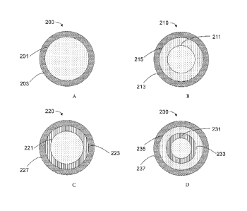
Cross-sectional views of example embodiments of the treatment particulates of
the
present disclosure are shown in Figures 3A-D. Referring now to Figure 3A,
treatment
particulate 200 includes a solid treatment chemical 201. Treatment particulate
200 also
includes a coating 203 disposed around the outermost surface of the solid
treatment chemical
201. While coating 203 is shown as completely encapsulating the solid
treatment chemical
201, the coating 203 in other embodiments of the present disclosure may only
cover some
portion of the outer surface of the solid treatment chemical 201.
Referring now to Figure 3B, another embodiment of a treatment particulate 210
of the
present disclosure is shown. Like treatment particulate 200 of Figure 3A,
treatment
particulate 210 includes a first solid treatment chemical 211 and a coating
213. However,
treatment particulate 210 also includes a second solid treatment chemical 215
disposed
around the outermost surface of the first solid treatment chemical 211. The
coating 213 is
disposed around the outermost surface of the second solid treatment chemical
215. In such
embodiments, the coating 213 may at least partially dissolve and/or degrade in
certain
environments or conditions (e.g., aqueous environments), which may result in
the release of
4
CA 02994933 2018-02-06
WO 2017/074393
PCT/US2015/058078
at least a portion of the second solid treatment chemical 215 into the
subterranean formation.
The release of at least a portion of the second solid treatment chemical 215
may result in the
release of at least a portion of the first solid treatment chemical 211 into
the subterranean
formation.
Another embodiment of a treatment particulate of the present disclosure is
shown in
Figure 3C. Referring now to Figure 3C, similar to the embodiment shown in
Figure 3A,
treatment particulate 220 includes a solid treatment chemical 221 and a
coating 223 disposed
around the outermost surface of the solid treatment chemical 221. In this
embodiment,
treatment particulate 220 also includes a second coating 227 that is disposed
around the
outermost surface of the first coating 223. In certain of these embodiments,
the first and
second coatings may, among other benefits, enhance the durability and/or
stability of
treatment particulate 220, and/or may be formulated to enhance its performance
where the
treatment particulate 220 may be subjected to multiple different environments
and/or
conditions in a subterranean formation. For example, the second coating 227
may prevent the
premature release of the treatment chemical 221 in certain types of
environments in which the
second coating 227 will not degrade or dissolve (e.g., aqueous environments),
while the first
coating 223 may prevent the premature release of the treatment chemical 221 in
certain types
of environments in which the first coating 223 will not degrade or dissolve
(e.g., oil-based
environments).
Another embodiment of a treatment particulate of the present disclosure is
shown in
Figure 3D. Referring now to Figure 3D, similar to the embodiments shown in
Figures 3A
and 3C, treatment particulate 230 includes a solid treatment chemical 231 and
a coating 233
that is disposed around the outermost surface of the solid treatment chemical
231. In this
embodiment, treatment particulate 230 also includes a second treatment
chemical 235 and
another coating 237 that is disposed around the outermost surface of the
second treatment
chemical 235. The first treatment chemical 231 and its coating 233 are
surrounded by the
second treatment chemical 235 and its coating 237.
Continuing to refer to Figure 3D as an illustrative example, in certain
embodiments,
the second treatment chemical 235 and/or coating 237 may comprise the same
materials as
solid treatment chemical 231 and coating 233, respectively. In other
embodiments, one or
more of those elements may differ from their counterparts (e.g., treatment
chemical 235 may
be a different treatment chemical from treatment chemical 231). In certain of
these
embodiments, the various components of treatment particulate 230 may be
formulated,
among other purposes, to allow for the selective release of multiple solid
treatment chemicals
5
CA 02994933 2018-02-06
WO 2017/074393
PCT/US2015/058078
(or different amounts of the same treatment chemical) in a single area of the
formation at
different points in time. For example, coating 237 may be selected to at least
partially
dissolve and/or degrade in certain environments or conditions (e.g., aqueous
environments)
while coating 233 does not dissolve or degrade in that environment or in those
conditions. As
a result, treatment chemical 235 may be released in that environment or
condition while
treatment chemical 231 is not. At some later point in time, after coating 237
has at least
partially dissolved and/or degraded, treatment particulate 230 may be exposed
to an
environment or condition in which coating 233 will at least partially dissolve
and/or degrade,
and thus treatment chemical 231 may be released at that point.
Any method known in the art may be used to form the solid treatment chemicals
of
the present disclosure. In some embodiments, the solid treatment chemicals may
be formed
from at least one treatment chemical by an extrusion process and/or a milling
process. In
certain embodiments, the solid treatment chemicals may be formed by co-
extruding two or
more treatment chemicals. In certain embodiments, the solid treatment
chemicals (either
prior to or after coating) may be cut or ground to a size and/or shape that
are similar to other
particulates (e.g., proppant particles) that are to be used in the same
treatment fluid and/or
subterranean formation.
The coating material may be applied to the outer surface of a solid chemical
treatment
to form a treatment particulate of the present disclosure using any means or
technique known
in the art, including, but not limited to, fluidized bed processes, pan
coating processes,
Wurster processes, top spray processes, spinning disk atomization processes,
chemical
encapsulation processes, extrusion, and the like. In extrusion methods, the
coating may be
co-extruded with one or more treatment chemicals such that the coating is
disposed on the
surface of the treatment chemical. In spray coating methods, the solid
treatment chemicals
will be suspended as particulates within a chamber and a coating sprayed onto
the surface. In
certain embodiments, by controlling the spray time, various coating thickness
can be applied,
among other reasons, to tailor the performance of the coated product. Examples
of chemical
coating techniques that may be suitable for coating the solid treatment
chemicals of the
present disclosure may include, but are not limited to, in situ solution
polymerization
techniques, interfacial polymerization techniques, emulsion polymerization
techniques,
simple and complex coacervation, and the like.
The shape of the treatment particulates of the present disclosure also may
provide a
further variable through which to control the diffusion of the treatment
chemicals into fluids
in contact with the treatment particulates. In certain embodiments, the
treatment particulates
6
CA 02994933 2018-02-06
WO 2017/074393
PCT/US2015/058078
may be of a cylindrical or rod-like shape. In certain embodiments, the
treatment particulates
may be of a substantially spherical shape. In some embodiments, a combination
of
cylindrical and spherical treatment particulates may be utilized.
The size of the treatment particulates of the present disclosure may provide a
further
variable through which to control the diffusion of the treatment chemicals
into fluids in
contact with the treatment particulates. In certain embodiments, the size of
the treatment
particulates of the present disclosure may be such that the treatment
particulates are
compatible with other particulates, for example, proppant particles. In
certain embodiments,
the treatment particulates having a cylindrical or rod-like shape may be from
about 0.1 mm to
about 5 mm in length. In some embodiments, the length of the treatment
particulates having
a cylindrical or rod-like shape may be from about 0.1 mm to about 1 mm, in
other
embodiments, from about 1 mm to about 2 mm, in other embodiments, from about 2
mm to
about 3 mm, in other embodiments, from about 3 mm to about 4 mm, and in other
embodiments, from about 4 mm to about 5 mm.
In certain embodiments, the elongated shape of certain treatment particulates
of the
present disclosure having a rod-like or cylindrical shape may increase the
void spaces
between the treatment particulates and/or the proppant particulates as
compared to the
treatment particulates having a substantially spherical shape. The increase in
void spaces
may in turn increase the conductivity of the proppant pack and/or may reduce
the non-Darcy
flow effect (a characterization of fluid flow that accounts for the turbulence
generated as the
oil or natural gas flows through the proppant pack). Non-Darcy fluid flow is
sometimes
problematic because it may strip the deposited treatment particulates and/or
proppant
particles from a fracture within the well bore, thus causing them to flow back
to the well bore
and/or to the surface of the subterranean formation with natural gas or oil
being produced. In
particular, it is believed that the use of a least some treatment particulates
having a rod-like or
cylindrical shape may reduce the turbulence component of the non-Darcy flow
effect as
compared to the use of only treatment particulates having a substantially
spherical shape.
Therefore, the shape of the treatment particulates of the present disclosure,
in some
embodiments, may at least partially allow the treatment particulates and/or
proppant particles
(or a substantial portion thereof) to remainin place in the formation and
prevent the flowback
of the treatment particulates and/or proppant particles into the well bore
and/or to the surface
of the subterranean formation. The prevention of flowback may, among other
benefits,
ensure that the treatment particulates and/or proppant particles reach their
intended location
in the formation and perform their intended function.
7
CA 02994933 2018-02-06
WO 2017/074393
PCT/US2015/058078
As exemplified in Figures 3A-D, the treatment particulates of the present
disclosure
may comprise one or more solid treatment chemicals and/or one or more coatings
in any
sequence, order, or combination. The one or more solid treatment chemicals
and/or one or
more coatings may be of any thickness appropriate for a particular application
of the present
disclosure, which a person of skill in the art with the benefit of this
disclosure will recognize.
Any treatment chemical in solid form that is useful downhole may be used as a
solid
treatment chemical in the present disclosure. Examples of treatment chemicals
that may be
suitable for certain embodiments of the present disclosure include, but are
not limited to,
chelating agents (e.g., EDTA, citric acid, polyaspartic acid), scale
inhibitors, gel breakers,
dispersants, paraffin inhibitors, asphaltene inhibitors, hydrate inhibitors,
corrosion inhibitors,
demulsifiers, foaming agents, defoamers, delinkers, crosslinkers, surfactants,
salts, acids,
catalysts, clay control agents, biocides, friction reducers, flocculants, H2S
scavengers, CO2
scavengers, oxygen scavengers, lubricants, viscosifiers, relative permeability
modifiers,
surfactants, wetting agents, filter cake removal agents, antifreeze agents and
any derivatives
and/or combinations thereof.
The coatings in the treatment particulates of the present disclosure may
comprise any
materials known in the art suitable for forming coatings on surfaces,
including, but not
limited to, polymeric materials. These coatings may be hydrophobic or
hydrophilic in nature,
depending on the intended use of the treatment particulate. Examples of
materials that may
be used to form coatings in the treatment particulates of the present
disclosure include, but
are not limited to, degradable polymers, copolymers, synthetic or natural
occurring resins,
nylon, waxes, drying oils, polyurethanes, polyacrylics, silicate materials,
glass materials,
inorganic durable materials, phenolics, biopolymers (e.g., cellulose),
polysaccharides,
hydrocolloids, gums, and any derivatives and/or combinations thereof. The
coating may be
of any thickness appropriate for a particular application of the present
disclosure, which a
person of skill in the art with the benefit of this disclosure will recognize.
In certain embodiments, the treatment particulates may be mixed with a
treatment
fluid. The treatment fluids used in the methods and compositions of the
present disclosure
may comprise any base fluid known in the art, including aqueous base fluids,
non-aqueous
base fluids, and any combinations thereof. The term "base fluid" refers to the
major
component of the fluid (as opposed to components dissolved and/or suspended
therein), and
does not indicate any particular condition or property of that fluid such as
its mass, amount,
pH, etc. Aqueous fluids that may be suitable for use in the methods of the
present disclosure
may comprise water from any source. Such aqueous fluids may comprise fresh
water, salt
8
CA 02994933 2018-02-06
WO 2017/074393
PCT/US2015/058078
water (e.g., water containing one or more salts dissolved therein), brine
(e.g., saturated salt
water), seawater, or any combination thereof In most embodiments of the
present disclosure,
the aqueous fluids comprise one or more ionic species, such as those formed by
salts
dissolved in water. For example, seawater and/or produced water may comprise a
variety of
divalent cationic species dissolved therein.
In certain embodiments, the density of the aqueous fluid can be adjusted,
among other
purposes, to provide additional particulate transport and suspension in the
compositions of
the present disclosure. In certain embodiments, the pH of the aqueous fluid
may be adjusted
(e.g., by a buffer or other pH adjusting agent) to a specific level, which may
depend on,
among other factors, the types of viscosifying agents, acids, and other
additives included in
the fluid. One of ordinary skill in the art, with the benefit of this
disclosure, will recognize
when such density and/or pH adjustments are appropriate.
Examples of non-aqueous fluids that may be suitable for use in the methods of
the
present disclosure include, but are not limited to, oils, hydrocarbons,
organic liquids, and the
like. In certain embodiments, the treatment fluids may comprise a mixture of
one or more
fluids and/or gases, including, but not limited to, emulsions, foams, and the
like.
In certain embodiments, the treatment fluids used in the methods and
compositions of
the present disclosure optionally may comprise any number of additional
additives other than
the treatment particulates of the present disclosure. Examples of such
additional additives
include, but are not limited to, salts, surfactants, acids, proppant
particulates, diverting agents,
fluid loss control additives, gas, nitrogen, carbon dioxide, surface modifying
agents,
tackifying agents, foamers, corrosion inhibitors, scale inhibitors, catalysts,
clay control
agents, biocides, friction reducers, antifoam agents, bridging agents,
flocculants, additional
H2S scavengers, CO2 scavengers, oxygen scavengers, lubricants, additional
viscosifiers,
breakers, weighting agents, relative permeability modifiers, resins, wetting
agents, coating
enhancement agents, filter cake removal agents, antifreeze agents (e.g.,
ethylene glycol), and
the like. In certain embodiments, one or more of these additional additives
(e.g., a
crosslinking agent) may be added to the treatment fluid and/or activated after
the viscosifying
agent has been at least partially hydrated in the fluid. A person skilled in
the art, with the
benefit of this disclosure, will recognize the types of additives that may be
included in the
fluids of the present disclosure for a particular application.
The present disclosure in some embodiments provides method for using the
treatment
particulates to carry out a variety of subterranean treatments. In certain
embodiments, the
treatment particulates may be introduced into a well bore penetrating at least
a portion of a
9
CA 02994933 2018-02-06
WO 2017/074393
PCT/US2015/058078
subterranean formation. In some embodiments, the treatment particulates may be
introduced
directly down hole, for example, into the annulus. In other embodiments, the
treatment
particulates may be mixed with a treatment fluid (for example, a fracturing
fluid) and the
treatment fluid may then be introduced into a well bore penetrating at least a
portion of a
subterranean formation. In certain embodiments, the treatment particulates may
be mixed
with a treatment fluid and a plurality of proppant particles. In such
embodiments, the
treatment particulates and the proppant particles may be deposited into at
least a portion of
the subterranean formation to form a proppant pack.
In certain embodiments, the coating may delay and/or control the release of
the solid
treatment chemical(s) in the subterranean formation. In certain embodiments,
the coating
may begin to dissolve, degrade, or otherwise be removed from the surface of
the outermost
treatment chemical due to the environment and/or conditions in a subterranean
formation
(e.g., temperature, pressure, contact with fluids). Once the coating has at
least partially been
removed from the treatment particulate, the solid treatment chemical may be
released into the
formation and/or interact with components in the subterranean formation, e.g.,
by diffusing
into fluids in contact the treatment particulates. In certain embodiments, the
treatment
particulates may comprise two of more solid treatment chemicals and the two or
more
treatment chemicals may react in situ within the subterranean formation to
form a different
treatment chemical. For example, a first solid treatment chemical may be
released into the
formation and then sometime after a second solid treatment chemical may be
released into the
formation and may react with the first solid treatment chemical.
Because the treatment particulates of the present disclosure are carrier-free
(i.e., lack a
carrier, a substrate, or the like), the treatment particulates may be
completely consumed over
some period of time. Thus, in certain embodiments, a residual porosity may be
created in at
least a portion of the subterranean formation, for example, in a proppant
pack, as the coating
begins to dissolve, degrade, or otherwise be removed from the surface of the
solid treatment
chemical and the solid treatment chemical is consumed.
The present disclosure in some embodiments provides methods for using the
treatment fluids to carry out a variety of subterranean treatments, including,
but not limited
to, hydraulic fracturing treatments, acidizing treatments, and drilling
operations. In some
embodiments, the treatment fluids of the present disclosure may be used in
treating a portion
of a subterranean formation, for example, in acidizing treatments such as
matrix acidizing or
fracture acidizing. In certain embodiments, a treatment fluid may be
introduced into a
subterranean formation. In some embodiments, the treatment fluid may be
introduced into a
CA 02994933 2018-02-06
WO 2017/074393
PCT/US2015/058078
well bore that penetrates a subterranean formation. In some embodiments, the
treatment fluid
may be introduced at a pressure sufficient to create or enhance one or more
fractures within
the subterranean formation (e.g., hydraulic fracturing).
Certain embodiments of the methods and compositions disclosed herein may
directly
or indirectly affect one or more components or pieces of equipment associated
with the
preparation, delivery, recapture, recycling, reuse, and/or disposal of the
disclosed
compositions. For example, and with reference to Figure 1, the disclosed
methods and
compositions may directly or indirectly affect one or more components or
pieces of
equipment associated with an exemplary fracturing system 10, according to one
or more
embodiments. In certain instances, the system 10 includes a fracturing fluid
producing
apparatus 20, a fluid source 30, a proppant source 40, and a pump and blender
system 50 and
resides at the surface at a well site where a well 60 is located. In certain
instances, the
fracturing fluid producing apparatus 20 combines a gel pre-cursor with fluid
(e.g., liquid or
substantially liquid) from fluid source 30, to produce a hydrated fracturing
fluid that is used
to fracture the formation. The hydrated fracturing fluid can be a fluid for
ready use in a
fracture stimulation treatment of the well 60 or a concentrate to which
additional fluid is
added prior to use in a fracture stimulation of the well 60. In other
instances, the fracturing
fluid producing apparatus 20 can be omitted and the fracturing fluid sourced
directly from the
fluid source 30. In certain instances, the fracturing fluid may comprise
water, a hydrocarbon
fluid, a polymer gel, foam, air, wet gases and/or other fluids.
The proppant source 40 can include a proppant for combination with the
fracturing
fluid. In certain embodiments, one or more treatment particulates of the
present disclosure
may be provided in the proppant source 40 and thereby combined with the
fracturing fluid
with the proppant. The system may also include additive source 70 that
provides one or more
additives (e.g., gelling agents, weighting agents, and/or other optional
additives) to alter the
properties of the fracturing fluid. For example, the other additives may be
provided in
additive source 70 can be included to reduce pumping friction, to reduce or
eliminate the
fluid's reaction to the geological formation in which the well is formed, to
operate as
surfactants, and/or to serve other functions. In certain embodiments, the
other additives may
be provided in additive source 70 may include one or more treatment
particulates of the
present disclosure.
The pump and blender system 50 receives the fracturing fluid and combines it
with
other components, including proppant from the proppant source 40 and/or
additional fluid
from the additive source 70. The resulting mixture may be pumped down the well
60 under a
11
CA 02994933 2018-02-06
WO 2017/074393
PCT/US2015/058078
pressure sufficient to create or enhance one or more fractures in a
subterranean zone, for
example, to stimulate production of fluids from the zone. Notably, in certain
instances, the
fracturing fluid producing apparatus 20, fluid source 30, and/or proppant
source 40 may be
equipped with one or more metering devices (not shown) to control the flow of
fluids,
proppant particles, and/or other compositions to the pumping and blender
system 50. Such
metering devices may permit the pumping and blender system 50 can source from
one, some
or all of the different sources at a given time, and may facilitate the
preparation of fracturing
fluids in accordance with the present disclosure using continuous mixing or
"on-the-fly"
methods. Thus, for example, the pumping and blender system 50 can provide just
fracturing
fluid into the well at some times, just proppant particles at other times, and
combinations of
those components at yet other times.
Figure 2 shows the well 60 during a fracturing operation in a portion of a
subterranean
formation of interest 102 surrounding a well bore 104. The well bore 104
extends from the
surface 106, and the fracturing fluid 108 is applied to a portion of the
subterranean formation
102 surrounding the horizontal portion of the well bore. Although shown as
vertical
deviating to horizontal, the well bore 104 may include horizontal, vertical,
slant, curved, and
other types of well bore geometries and orientations, and the fracturing
treatment may be
applied to a subterranean zone surrounding any portion of the well bore. The
well bore 104
can include a casing 110 that is cemented or otherwise secured to the well
bore wall. The
well bore 104 can be uncased or include uncased sections. Perforations can be
formed in the
casing 110 to allow fracturing fluids and/or other materials to flow into the
subterranean
formation 102. In cased wells, perforations can be formed using shape charges,
a perforating
gun, hydro-jetting and/or other tools.
The well is shown with a work string 112 depending from the surface 106 into
the
well bore 104. The pump and blender system 50 is coupled a work string 112 to
pump the
fracturing fluid 108 into the well bore 104. The working string 112 may
include coiled
tubing, jointed pipe, and/or other structures that allow fluid to flow into
the well bore 104.
The working string 112 can include flow control devices, bypass valves, ports,
and or other
tools or well devices that control a flow of fluid from the interior of the
working string 112
into the subterranean zone 102. For example, the working string 112 may
include ports
adjacent the well bore wall to communicate the fracturing fluid 108 directly
into the
subterranean formation 102, and/or the working string 112 may include ports
that are spaced
apart from the well bore wall to communicate the fracturing fluid 108 into an
annulus in the
well bore between the working string 112 and the well bore wall.
12
CA 02994933 2018-02-06
WO 2017/074393
PCT/US2015/058078
The working string 112 and/or the well bore 104 may include one or more sets
of
packers 114 that seal the annulus between the working string 112 and well bore
104 to define
an interval of the well bore 104 into which the fracturing fluid 108 will be
pumped. Figure 2
shows two packers 114, one defining an uphole boundary of the interval and one
defining the
downhole end of the interval. When the fracturing fluid 108 is introduced into
well bore 104
(e.g., in Figure 2, the area of the well bore 104 between packers 114) at a
sufficient hydraulic
pressure, one or more fractures 116 may be created in the subterranean zone
102. The
proppant particulates (and/or treatment particulates of the present
disclosure) in the fracturing
fluid 108 may enter the fractures 116 where they may remain after the
fracturing fluid flows
out of the well bore. These proppant particulates may "prop" fractures 116
such that fluids
may flow more freely through the fractures 116.
While not specifically illustrated herein, the disclosed methods and
compositions may
also directly or indirectly affect any transport or delivery equipment used to
convey the
compositions to the fracturing system 10 such as, for example, any transport
vessels,
conduits, pipelines, trucks, tubulars, and/or pipes used to fluidically move
the compositions
from one location to another, any pumps, compressors, or motors used to drive
the
compositions into motion, any valves or related joints used to regulate the
pressure or flow
rate of the compositions, and any sensors (i.e., pressure and temperature),
gauges, and/or
combinations thereof, and the like.
An embodiment of the present disclosure is a method comprising: providing a
plurality of carrier-free treatment particulates comprising at least one solid
treatment
chemical and a coating at least partially disposed around an outer surface of
the solid
treatment chemical; and introducing the plurality of carrier-free treatment
particulates into a
well bore penetrating at least a portion of a subterranean formation, wherein
the plurality of
carrier-free treatment particulates is at least partially consumed in the
subterranean formation
to create a residual porosity in the portion of the subterranean formation.
Another embodiment of the present disclosure is a method comprising: forming a
particulate comprising a solid treatment chemical by subjecting the treatment
chemical to an
extrusion process, a milling process, or any combination thereof; placing a
coating on an
outer surface of the solid treatment chemical particulate to form a carrier-
free treatment
particulate; and
introducing the carrier-free treatment particulate into a well bore
penetrating at least a portion of a subterranean formation.
Another embodiment of the present disclosure is a treatment particulate
composition
comprising: a first solid treatment chemical; a second solid treatment
chemical disposed
13
CA 02994933 2018-02-06
WO 2017/074393
PCT/US2015/058078
around an outer surface of the first solid treatment chemical; and a coating
disposed around
an outer surface of the second solid treatment chemical, wherein the treatment
particulate is
carrier-free.
Therefore, the present disclosure is well adapted to attain the ends and
advantages
mentioned as well as those that are inherent therein. The particular
embodiments disclosed
above are illustrative only, as the present disclosure may be modified and
practiced in
different but equivalent manners apparent to those skilled in the art having
the benefit of the
teachings herein. While numerous changes may be made by those skilled in the
art, such
changes are encompassed within the spirit of the subject matter defined by the
appended
claims. Furthermore, no limitations are intended to the details of
construction or design
herein shown, other than as described in the claims below. It is therefore
evident that the
particular illustrative embodiments disclosed above may be altered or modified
and all such
variations are considered within the scope and spirit of the present
disclosure. In particular,
every range of values (e.g., "from about a to about b," or, equivalently,
"from approximately
a to b," or, equivalently, "from approximately a-b") disclosed herein is to be
understood as
referring to the power set (the set of all subsets) of the respective range of
values. The terms
in the claims have their plain, ordinary meaning unless otherwise explicitly
and clearly
defined by the patentee.
14