Note: Descriptions are shown in the official language in which they were submitted.
CA 02995147 2018-02-08
WO 2017/037212
PCT/EP2016/070680
- 1 -
BEVERAGE MACHINE WITH ERGONOMIC OUTLET
Field of the Invention
The field of the invention pertains to beverage
preparation machines provided with an ergonomic beverage
outlet, e.g. machines using capsules of an ingredient of
the beverage to be prepared.
For the purpose of the present description, a
"beverage" is meant to include any human-consumable
liquid substance, such as tea, coffee, hot or cold
chocolate, milk, soup, baby food, etc_ A "capsule" is
meant to include any pre-portioned beverage ingredient,
such as a flavouring ingredient, within an enclosing
packaging of any material, in particular an airtight
packaging, e.g. plastic, aluminium, recyclable and/or
biodegradable packagings, and of any shape and structure,
including soft pods or rigid cartridges containing the
ingredient. The capsule may contain an amount of
ingredient for preparing a single beverage portion or a
plurality of beverage portions.
Background Art
Certain beverage preparation machines use capsules
containing ingredients to be extracted or to be dissolved
and/or ingredients that are stored and dosed
automatically in the machine or else are added at the
time of preparation of the drink. Some beverage machines
possess filling means that include a pump for liquid,
usually water, which pumps the liquid from a source of
water that is cold or indeed heated through heating
means, e.g. a thermoblock or the like.
Especially in the field of coffee preparation,
machines have been widely developed in which a capsule
containing beverage ingredients is inserted in a brewing
device. The brewing device is tightly closed about the
capsule, water is injected at the first face of the
capsule, the beverage is produced in the closed volume of
the capsule and a brewed beverage can be drained from a
second face of the capsule and collected into a
receptacle such as a cup or glass.
CA 02995147 2018-02-08
WO 2017/037212
PCT/EP2016/070680
- 2 -
Brewing devices have been developed to facilitate
insertion of a "fresh" capsule and removal of the capsule
upon use. Typically, the brewing devices comprise two
parts relatively movable from a configuration for
inserting/removing a capsule to a configuration for
brewing the ingredient in the capsule.
The actuation of the movable part of the brewing
device may be manual as disclosed in WO 2009/043630, WO
01/15581, WO 02/43541, WO 2010/015427, WO 2010/128109, WO
2011/144719 and WO 2012/032019. Various handle
configurations are disclosed in EP 1867260, WO
2005/004683, WO W02007/135136, WO 2008/138710, WO
2009/074550, WO 2009/074553, WO 2009/074555, WO
2009/074557, WO 2009/074559, WO 2010/037806, WO
2011/042400, WO 2011/042401 and WO 2011/144720.
Integrations of such arrangements into beverage machines
are disclosed in WO 2009/074550, W02011/144719,
EP2014195046, EP2014195048 and EP2014195067.
The actuation of the movable part of the brewing
device may be motorized. Such a system is for example
disclosed in EP 1 767 129. In this case, the user does
not have to provide any manual effort to open or close
the brewing device. The brewing device has a capsule
insertion passage provided with a safety door assembled
to the movable part of the brewing device via a switch
for detecting an undesired presence of a finger in the
passage during closure and prevent injuries by squeezing.
Alternative covers for a capsule insertion passage are
disclosed WO 2012/093107 and WO 2013/127906. Different
motorization systems are disclosed in WO 2012/025258, WO
2012/025259 and WO 2013/127476.
For allowing the user to interact with such
machines, for providing operation instructions to the
machine or obtaining feed-back therefrom, various systems
have been disclosed in the art, for instance as mentioned
in the following references: AT 410 377, CH 682 798, DE
44 29 353, DE 202 00 419, DE 20 2006 019 039, DE 2007 008
590, EP 1 448 084, EP 1 676 509, EP 08155851.2, FR 2 624
844, GB 2 397 510, US 4,377,049, US 4,458,735, US
4,554,419, US 4,767,632, US 4,954,697, US 5,312,020, US
5,335,705, US 5,372,061, US 5,375,508, US 5,645,230, US
CA 02995147 2018-02-08
WO 2017/037212
PCT/EP2016/070680
-3-
5,685,435, US 5,731,981, US 5,836,236, US 5,959,869, US
6,182,555, US 6,354,341, US 6,759,072, US 2007/0157820,
WO 97/25634, W099/50172, WO 2004/030435, WO 2004/030438,
WO 2006/063645, WO 2006/090183, WO 2007/003062, WO
2007/003990, WO 2008/104751, WO 2008/138710, WO
2008/138820, WO 2010/003932, WO 2011/144720 and WO
2012/032019.
WO 2006/050881 discloses a milk frother that has a
dispensing head for dispensing the frother milk. The
dispensing head is retractable inside the forther's
housing for the time needed at the end of a dispensing
cycle to perform a cleaning cycle of the dispensing head.
Summary of the Invention
The invention relates to a machine for preparing a
beverage. The beverage preparation machine can be an in-
home or out of home machine. The machine may be for the
preparation of coffee, tea, chocolate, cacao, milk, soup,
baby food, etc_
The beverage preparation typically includes the mixing
of a plurality of beverage ingredients, e.g. water and
milk powder, and/or the infusion of a beverage
ingredient, such as an infusion of ground coffee or tea
with water. One or more of such ingredients may be
supplied in loose and/or agglomerate powder form and/or
in liquid form, in particular in a concentrate form. A
carrier or diluents liquid, e.g. water, may be mixed with
such ingredient to form the beverage. Typically, a
predetermined amount of beverage is formed and dispensed
on user-request, which corresponds to a portion (e.g. a
serving). The volume of such portion may be in the range
of 25 to 200 ml and even up to 300 or 400 ml, e.g. the
volume for filling a cup, depending on the type of
beverage. Formed and dispensed beverages may be selected
from ristrettos, espressos, lungos, cappuccinos, latte
macchiato, café latte, americano coffees, teas, etc... In
particular, a coffee machine may be configured for
dispensing espressos, e.g. an adjustable volume of 20 to
60 ml per portion, and/or for dispensing lungos, e.g. a
volume in the range of 70 to 150 ml per portion.
CA 02995147 2018-02-08
WO 2017/037212
PCT/EP2016/070680
- 4 -
The machine of the invention has a main body
containing a unit for preparing the beverage to be
dispensed via an outlet to an external user-recipient at
a user-recipient placement location. The beverage
preparation unit may include a flow circuit with at least
one of: a source of liquid e.g. water; a liquid sensor
e.g. a flowmeter; a pump for driving a liquid from a or
said source to the outlet, e.g. a solenoid pump
(reciprocating piston pump) or a peristaltic pump or a
diaphragm pump; and a thermal fluid conditioner such as a
heater and/or a cooler.
The thermal conditioner may be a boiler or a
thermoblock or an on demand heater (ODH), for instance an
ODH type disclosed in EP 1 253 844, EP 1 380 243 and EP 1
809 151.
Examples of pumps and their incorporation into
beverage machines are disclosed in WO 2009/150030, WO
2010/108700, WO 2011/107574 and WO 2013/098173.
The placement location can be associated with a
machine recipient support for supporting such user-
recipient under the outlet. The support can be:
associated with a drip tray e.g. a drip tray supporting
the support; and/or movable relative to the housing
vertically under the outlet and/or away from under the
outlet for enabling a placement of user-recipients of
different heights under the outlet. Examples of suitable
recipient supports are disclosed in EP 0 549 887, EP 1
440 639, EP 1 731 065, EP 1 867 260, US 5,161,455, US
5,353,692, WO 2009/074557, WO 2009/074559, WO
2009/135869, WO 2011/154492, WO 2012/007313, WO
2013/186339, EP 2014198712, EP 2014198710 and EP
2014198715.
The machine of the invention has a beverage dispensing
head that includes the outlet and that is movable
relative to the main body:
- inwards into the main body into a retracted head
position; and
- outwards from the main body into a deployed head
position.
CA 02995147 2018-02-08
WO 2017/037212
PCT/EP2016/070680
- 5 -
The user-recipient placement location can be located
vertically below the outlet when the head is in its
deployed position.
The machine of the invention has a control unit for
controlling the preparation unit to supply the beverage
to the outlet.
For instance, the control unit is connected to a user-
interface. The user-interface can be located on the
dispensing head and movable therewith.
Hence, the user-interface can be part of the movable
dispensing head and is thus deployed when the dispensing
head is moved into its deployed position (typically in
view of preparing and dispensing a beverage or servicing
the beverage preparation unit) and is retracted when the
dispensing head is moved into its retracted position
(typically in the absence of preparing and dispensing a
beverage or servicing the beverage preparation unit). The
user-interface is thus linked to the movement of the
dispensing head and brought forward in front of the
machine with the or a visually prominent machine part and
thus immediately brought to the user's attention when the
user-interface is likely to be needed. Such a
configuration thus enhances the user convenience
resulting from the positioning of the user-interface in
view of an expected high use or reduced use or non-use
thereof.
For instance, the user-interface includes an apparent
user-interface that is accessible to a user when the head
is in the deployed position and that remains accessible
to a user when the head is in its retracted position. The
apparent user-interface can be configured to receive
user-instructions when the beverage preparation unit is
not in operation. The apparent user-interface may be
configured to receive user-instructions when the beverage
preparation unit is in operation. Such an apparent user-
interface can be used both when the dispensing head is in
its deployed position (e.g. for setting beverage
preparation parameters and/or requesting a beverage
preparation and dispensing, or for setting servicing
parameters and/or for requesting a servicing of the
beverage preparation unit) and when the dispensing head
CA 02995147 2018-02-08
WO 2017/037212
PCT/EP2016/070680
- 6 -
is in its retracted position (e.g. for powering the
machine, e.g. to start-up the machine from a switched off
or a standby mode, or for entering a beverage preparation
or servicing mode).
The user-interface may include a retractable user-
interface that is: retracted in the main body when the
head is in its retracted position; and deployed out of
the main body when the head is in its deployed position.
Thereby, the retractable user-interface is accessible to
a user in the deployed position and inaccessible (or
hidden) to a user in the retracted position. The
retractable user-interface can be configured to receive
user-instructions when the beverage preparation unit is
in operation, such as an user-instruction to interrupt
operation (e.g. to request a beverage preparation and
dispensing or servicing of the machine, or to interrupt
such beverage preparation and dispensing or service of
the machine). Typically, the retractable user-interface
is configured to not receive any user-instruction when in
the retracted position.
The outlet can be confined in the main body when the
beverage dispensing head is in its retracted position.
In accordance with the invention, the control unit is
configured to:
- maintain or leave the beverage dispensing head in its
retracted position when the beverage preparation unit
is not operated to process a liquid such as the
beverage or a cleaning liquid; and/or
- move the beverage dispensing head into its deployed
position or maintain or leave it in this position only
when the control unit operates the preparation unit to
process a liquid for dispensing via the outlet.
It follows that the beverage dispensing head is not
moved from its retracted position into deployed position
unless it is for operating the beverage preparation unit
to prepare a beverage or process other liquids.
The machine can be configured to deploy its beverage
dispensing head only when the machine is operating to
prepare beverage or process other liquids (e.g. in a
cleaning or descaling cycle) to be dispensed via the
CA 02995147 2018-02-08
WO 2017/037212
PCT/EP2016/070680
- 7 -
dispensing head's outlet. The remaining time, especially
when the machine is not in activity, the machine can be
left in a compact state with the beverage dispensing head
retracted.
The control unit is typically configured to operate
the preparation unit to prepare the beverage when the
beverage dispensing head is in its deployed position.
The control unit can be configured to operate the
preparation unit to service the unit when the beverage
dispensing head is in its deployed position. The
servicing can involve a descaling program, such as a
descaling with a volume of descaling water corresponding
to a plurality of plurality of beverage portions
delivered via the outlet to a service recipient at said
placement location.
The control unit may be configured to operate the
preparation unit to evacuate residual beverage when the
beverage dispensing head is in its deployed position or
when it is in its retracted position or when it is moved
to the deployed position or when it is moved to the
retracted position. Therefor the preparation unit can be
operated for rinsing the outlet, such as a rinsing with a
volume of rinsing water corresponding to a single
beverage portion or less delivered via the preparation
unit to a waste collector, e.g. a waste collector located
in main body and optionally removable therefrom.
The beverage dispensing head can be moved into its
retracted position in at least one of the following
instances:
- immediately at the end of servicing the beverage
preparation unit;
- immediately at the end of preparing a portion of
beverage by the beverage preparation unit or after a
short period of time after the end, such as a period
of time in the range of 1 to 15 sec, such as 3 to 12
sec, e.g. 5 to 10 sec, the beverage dispensing head
being for instance maintained in its deployed position
upon preparing a portion of beverage to allow during
such short period of time a user to request the
CA 02995147 2018-02-08
WO 2017/037212
PCT/EP2016/070680
- 8 -
preparation of a further portion of beverage by the
preparation unit; and
- in the absence of a detection by a sensor connected to
the control unit of a user-recipient in the placement
location, the sensor being for instance an optical or
a proximity sensor.
The beverage dispensing head can be moved into its
deployed position:
- on a user-request of a beverage preparation or of a
servicing of the preparation unit; and/or
- on a detection by a sensor connected to the control
unit of a user-recipient in the placement location,
the sensor being for instance an optical or a
proximity sensor.
The beverage preparation unit can have an ingredient
mixing module which comprises a first part and a second
part that are relatively movable, e.g. by a motor,
between a mixing position for mixing ingredients and a
transfer position for inserting an ingredient and/or
removing waste (e.g. residual or waste ingredient(s))
from the mixing module. For instance, the module is in
fluid connection with a source of liquid such as water.
The source of liquid can be connected to the module via
one or more of: a liquid sensor such as a flowmeter, a
pump for driving a liquid from the source to the module
and then the outlet, and a thermal fluid conditioner such
as a heater and/or a cooler.
Examples of suitable mixing modules with first and
second parts that are relatively moved by a motor are
disclosed in EP 1767129, WO 2012/025258, WO 2012/025259,
WO 2013/127476 and WO 2014/056641.
For instance, the first part and the second part of
the mixing module are relatively movable generally along
a longitudinal straight axis.
Typically, the first and second parts of the mixing
module are distant from each other in the transfer
position and close to each other in the mixing position.
In the mixing position, the first and second parts may
define a mixing chamber, e.g. a chamber for receiving a
CA 02995147 2018-02-08
WO 2017/037212
PCT/EP2016/070680
- 9 -
plurality of beverage ingredients to be mixed together.
In one embodiment, the mixing chamber is an infusion
chamber in which infusible ingredients, e.g. coffee or
tea, are exposed to a carrier liquid, such as water e.g.
hot water. The mixing chamber may be configured to
receive loose solid ingredient particles and/or to
receive proportioned ingredients within a capsule.
At least one part of the first and second parts may
delimit a cavity for receiving the ingredient e.g. within
a capsule, such as a tapered cavity, e.g. a conical or
pyramidal cavity, or a straight cavity, e.g. a
cylindrical or trapezoidal cavity. Such cavity may extend
along an axis that is generally collinear with the above
longitudinal straight axis.
The other part of these first and second parts may
include an extraction plate, such as a plate provided
with piercing elements for opening a flow-through face of
the capsule or a non-intrusive plate for cooperating with
a pre-opened or a self-opening flow-through face of the
capsule.
Self-opening capsules are for instance disclosed in CH
605 293 and WO 03/059778.
The opening of capsules by a machine's piercing
elements of a plate are for example disclosed in EP 512
470 and EP 2 068 684.
Examples of suitable mixing modules with mixing
chambers are disclosed in WO 2008/037642 and WO
2013/026843.
A flavoured beverage may be prepared by circulating
(by means of a liquid driver, e.g. a pump) a carrier
liquid, such as water, into the capsule to flavour the
liquid by exposure to a flavouring ingredient held in the
capsule, e.g. along an extraction direction that may be
generally parallel to the direction of relative movement
of the first and second parts of the mixing module.
When closed capsules are used, the first and second
parts may include a capsule opener such as blades and/or
a tearing tool, e.g. a plate with a tearing profile, for
instance as known from NespressoTM machines or as
CA 02995147 2018-02-08
WO 2017/037212
PCT/EP2016/070680
- 10 -
disclosed in EP 0 512 470, EP 2 068 684 and WO
2014/076041 and the references cited therein.
The beverage dispensing head can be mechanically
connected or linked, e.g. via a cam arrangement and/or a
gear arrangement such as a spur and/or friction gear
arrangement, to one of the first and second part that is
movable in the main body so that the dispensing head is
moved into:
- its deployed position when the first and second parts
are relatively moved into the mixing position; and
- its retracted position when the first and second parts
are relatively moved into the transfer position.
Hence, a common actuator, e.g. a single motor, can
drive the dispensing head and the said one of the first
and second parts relative to the main body. In such a
case, the said one of the first and second parts can be
moved: simultaneously with the dispensing head; or can be
moved sequentially or partly sequentially (and partly
simultaneously) after or before moving the dispensing
head.
The said one of the first and second part can form an
upstream part or a downstream part of the mixing module.
The beverage dispensing head and the said one of the
first and second parts can be mechanically
disconnectable, e.g. via a connection actuator controlled
by the control unit such as a magnetic actuator, so as to
allow a relative movement of the first and second parts
without moving the dispensing head.
The beverage dispensing head in the deployed position
and the said one of the first and second parts in the
mixing position can be mechanically disconnected to
relatively move the first and second parts back and forth
between the mixing position and the transfer position
when a user requests the preparation of a further portion
of beverage by the preparation unit:
- before the end of preparing a portion of beverage by
the preparation unit; or
- within a short period of time after the end of
preparing a portion of beverage by the preparation
CA 02995147 2018-02-08
WO 2017/037212
PCT/EP2016/070680
- 11 -
unit, such as a period of time in the range of 1 to 15
sec, such as 3 to 12 sec, e.g. 5 to 10 sec.
Hence, a user can request the dispensing of two (or
more) portions of beverages into the same user-recipient
without moving the dispensing head into its retracted
position while reloading the mixing unit.
The control unit can be configured to disconnect the
dispensing head in its retracted position from the said
one of the first and second parts to relatively move the
first and second parts into the mixing position, e.g. to
unclog the mixing module or to rinse the mixing module
such as a rinsing with a volume of rinsing water
corresponding to a single beverage preparation or less
delivered via the preparation unit to a waste collector,
and then to relatively move the first and second parts
back into the transfer position, e.g. a waste collector
located in the main body and optionally removable
therefrom.
The main body typically has a transfer channel for
supplying an ingredient to the mixing module, e.g. the
main body comprises or delimits such a transfer channel.
The channel may extend to a waste collector, e.g. a waste
collector located in the main body and optionally
removable therefrom.
The interaction between the first and second parts
(and optionally the transfer channel) and an ingredient
capsule may be of the type disclosed in WO 2005/004683,
WO 2007/135135, W02007/135136, WO 2008/037642 and WO
2013/026856.
The machine may include a capsule loader associated
with the transfer channel for loading a capsule.
The capsule to be loaded may be of the type described
above under the title "Field of the Invention" and/or the
capsule may include an ingredient described under the
same title.
The capsule can comprise a capsule body, e.g. a
generally straight or tapered body. The capsule can have
a circular peripheral annulus flange, e.g. a flexible or
rigid flange, extending from a peripheral part, e.g. an
edge or face, of the capsule body. The capsule may
CA 02995147 2018-02-08
WO 2017/037212
PCT/EP2016/070680
- 12 -
contain a flavoring ingredient for preparing tea, coffee,
hot chocolate, cold chocolate, milk, soup or baby food.
The capsule loader may have: a capsule holding
configuration for holding an ingredient capsule away from
the mixing module; and a capsule releasing configuration
for releasing the capsule in or into the transfer channel
towards the mixing module.
The loader may have a capsule gate that is movable,
such as pivotable and/or translatable, between a position
obstructing the transfer channel for preventing a passage
of the capsule along the channel and a position clearing
the transfer channel for allowing a passage of the
capsule along the channel.
Immediately after releasing a capsule to the mixing
module, the loader may be passed from the releasing
configuration to the holding configuration so that the
transfer channel is opened only when needed to release a
capsule.
The loader can have a shape complementary to a shape
of the capsule.
The loader may have an actuator for passing from the
holding configuration to the releasing configuration and
vice versa, such as an actuator controlled by the control
unit.
Details of suitable capsule loaders are disclosed in
WO 2012/126971, WO 2014/056641, WO 2014/056642 and WO
2015/086371.
The loader may have a capsule sensor for sensing a
presence of a capsule on the capsule loader and
optionally sensing a type of the capsule. The capsule
loader can be controlled by the control unit to
automatically release a sensed capsule when the mixing
module is in the transfer position. When a particular
type of capsule is identified, the control unit may adapt
the control of the preparation unit of the beverage
according to the identified type.
Details of suitable capsule sensing are disclosed in
WO 2012/123440, WO 2014/147128,
PCT/EP15/060555,
CA 02995147 2018-02-08
WO 2017/037212
PCT/EP2016/070680
- 13 -
PCT/EP15/060561, PCT/EP15/060567, PCT/EP15/065415 and
PCT/EP15/065535.
Advantageously, the machine has a directing fluid
guide upstream the outlet and downstream the preparation
unit, the directing guide being configured to direct
residual liquid from the preparation unit to a waste
collector when the preparation unit is not operated to
process a beverage, e.g. a waste collector located in the
main body and optionally removable therefrom. The
directing fluid guide, the outlet and the preparation
unit can be configured so that the directing fluid guide
directs liquid from the preparation unit: in a dispensing
configuration to the outlet when the dispensing head is
in its deployed position; and in a collecting
configuration to the waste collector when the dispensing
head is in its retracted position.
The directing fluid guide can have a guide inlet in
fluid connection with the preparation unit so that the
guide inlet is:
- directly connected to the preparation unit, the
directing fluid guide having a guide outlet or
draining edge that is in fluidic communication
selectively with the dispensing head outlet or with
the waste collector; or
- separate from the preparation unit, the directing
fluid guide having:
- a collecting surface, e.g. a channel of funnel, for
collecting liquid flowing from an outlet of the
preparation unit, e.g. of a mixing module of the
preparation unit; and
- at least one guide outlet or draining edge for
directing the liquid collected by the collecting
surface to the dispensing head outlet and/or to the
waste collector, such as: a single guide outlet or
draining edge for directing the liquid selectively
to the head outlet or to the waste collector; or a
first guide outlet or draining edge for draining
the liquid to the head outlet and a second guide
outlet or draining edge for directing the liquid to
the waste collector.
CA 02995147 2018-02-08
WO 2017/037212
PCT/EP2016/070680
- 14 -
The directing fluid guide can be actuated between the
dispensing configuration and the collecting configuration
by an actuator controlled by the control unit.
The directing fluid guide can be entirely confined in
the main body and/or the dispensing head.
Details of directing fluid guides that are suitable or
adaptable for carrying out the present invention are
disclosed in WO 2006/050769, WO 2012/072758, WO
2013/127907 and EP2014195067.5.
The directing guide and the dispensing head may be
mechanically connected, e.g. by a cam arrangement and/or
a gear arrangement such as a spur and/or friction gear
arrangement, so that the movement of the dispensing head:
- from its retracted position into its deployed position
is linked to or causes or is caused by a relative
movement of the directing device into the dispensing
configuration to direct fluid to the outlet; and/or
- from its deployed position into its retracted position
is linked to or causes or is caused by a relative
movement of the directing device into the collecting
configuration to direct fluid to the waste collector.
The dispensing head can be configured to translate
along a straight direction from the retracted position
into the deployed position and vice versa. For instance,
the beverage preparation unit has an ingredient mixing
module which comprises a first part and a second part
that are relatively movable generally along this straight
direction between a mixing position for mixing
ingredients and a transfer position for inserting an
ingredient and/or removing waste from the mixing module.
The ingredient mixing module may be of the type described
above.
The dispensing head may be configured to move:
- inwards into an outside housing or frame of the main
body into the retracted position; and
- outwards of the outside housing or frame into a
deployed position.
For instance, the dispensing head in the retracted
position has an outside face, e.g. a front face, that is
CA 02995147 2018-02-08
WO 2017/037212
PCT/EP2016/070680
- 15 -
flush, e.g. entirely flush, with the outside housing or
frame. Hence, the dispensing head in the retracted
position can be entirely sunk into main body.
Examples of suitable waste collectors for carrying out
the present invention are disclosed in EP 1867260, WO
2009/074559, WO 2009/135869, WO 2010/128109, WO
2011/086087 and WO 2011/086088.
Brief Description of the Drawings
The invention will now be described with reference
to the schematic drawings, wherein:
- Figure 1 schematically illustrates a machine according
to the invention having a beverage preparation unit
with an ingredient mixing module in a transfer
position and an ingredient capsule on a loader for
being transferred to the mixing module;
- Figure 2 schematically illustrates the machine of Fig.
1 upon release by the loader of the ingredient capsule
to the mixing module;
- Figure 3 schematically illustrates the machine of Fig.
1 with the ingredient mixing module in the mixing
position and the beverage dispensing head in the
retracted position prior to beverage dispensing;
- Figure 4 schematically illustrates the machine of Fig.
1 with the beverage dispensing head in the deployed
position for dispensing via the head's outlet a
beverage to a user-recipient;
- Figure 5 schematically illustrates the machine of Fig.
1 with the dispensing head in the retracted position
after beverage dispensing; and
- Figure 6 schematically illustrates the machine of Fig.
1 with the mixing module in the transfer position
after beverage dispensing whereby the ingredient
capsule is transferred to a waste collector.
Detailed description
Figures 1 to 6 illustrate an exemplary embodiment of a
beverage machine 1 in accordance with the invention. The
CA 02995147 2018-02-08
WO 2017/037212
PCT/EP2016/070680
- 16 -
ingredient may be supplied in the form of an ingredient
capsule 4, e.g. of the type described above under the
header "Field of the Invention". The sequence from Fig. 1
to Fig. 6 illustrates a beverage preparation sequence in
machine 1 from the supply of an ingredient, e.g. an
ingredient capsule 4, to the removal of the used
ingredient, e.g. capsule 4, upon beverage preparation.
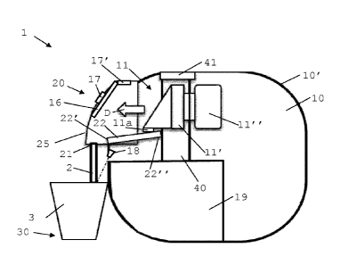
Machine 1 has a main body 10 containing a unit
11,12,13,14,15 for preparing beverage 2 to be dispensed
via an outlet 21 to an external user-recipient 3 at a
user-recipient placement location 30. For instance,
beverage preparation unit 11,12,13,14,15 comprises a flow
circuit with at least one of: a source 12 of liquid e.g.
water, a liquid sensor 13 e.g. a flowmeter, a pump 14 for
driving a liquid from a or said source 12 to the outlet
21, and a thermal fluid conditioner 15 such as a heater
and/or a cooler, as illustrated in Fig. 1.
Machine 1 has a beverage dispensing head 20 that
includes outlet 21 and that is movable relative to main
body 10 inwards into main body 10 into a retracted head
position (Figs 1, 2, 3, 5 and 6) and outwards from main
body 10 into a deployed head position (Fig. 4). For
instance, user-recipient placement location 30 is located
vertically below outlet 21 when head 20 is in its
deployed position. See Fig. 4.
Arrow D in Fig. 4 illustrates the movement of
dispensing head 20 into the deployed position. Arrow E in
Fig. 5 illustrates the movement of dispensing head 20
into the retracted position.
Machine 1 includes a control unit 16 for controlling
preparation unit 11,12,13,14,15 to supply beverage 2 to
outlet 21. For instance, control unit 16 is connected to
a user-interface 17,17', such as a user-interface 17,17'
located on dispensing head 20 and movable therewith, e.g.
a user-interface 17 that remains accessible to a user
when head 20 is in its retracted position and/or a user-
interface 17' that is accessible to a user in the
deployed position and inaccessible (or hidden) to a user
in the retracted position. See Figs. 1 and 4.
CA 02995147 2018-02-08
WO 2017/037212
PCT/EP2016/070680
- 17 -
Outlet 21 can be confined in main body 10 when
beverage dispensing head 20 is in its retracted position.
See Figs 1, 2, 3, 5 and 6.
Control unit 16 is configured to:
- maintain or leave beverage dispensing head 20 in its
retracted position when beverage preparation unit
11,12,13,14,15 is not operated to process a liquid
such as beverage 2; and/or
- move beverage dispensing head 20 into its deployed
position or maintain or leave it in this position only
when control unit 16 operates preparation unit
11,12,13,14,15 to process a liquid for dispensing via
outlet 21.
Control unit 16 is typically configured to operate
preparation unit 11,12,13,14,15 to prepare beverage 2
when beverage dispensing head 20 is in its deployed
position.
Control unit 16 may be configured to operate
preparation unit 11,12,13,14,15 to service unit
11,12,13,14,15 when beverage dispensing head 20 is in its
deployed position, for instance to carry out a descaling
program, such as a descaling with a volume of descaling
water corresponding to a plurality of beverage portions
delivered via outlet 21 to a service recipient at said
placement location 30.
Control unit 16 may be configured to operate
preparation unit 11,12,13,14,15 to evacuate residual
beverage when beverage dispensing head 20 is in its
deployed position or when it is in its retracted position
or when it is moved to the deployed position or when it
is moved to the retracted position. For instance,
preparation unit 11,12,13,14,15 is operated for rinsing
outlet 21, such as a rinsing with a volume of rinsing
water corresponding to a single beverage portion or less
delivered via preparation unit 11,12,13,14,15 to a waste
collector 19, e.g. a waste collector 19 located in main
body 10 and optionally removable therefrom.
Beverage dispensing head 20 may be moved into its
retracted position in at least one of the following
instances:
CA 02995147 2018-02-08
WO 2017/037212
PCT/EP2016/070680
- 18 -
- immediately at the end of servicing beverage
preparation unit 11,12,13,14,15;
- immediately at the end of preparing a portion of
beverage by beverage preparation unit 11,12,13,14,15
or after a short period of time after the end, such as
a period of time in the range of 1 to 15 sec, such as
3 to 12 sec, e.g. 5 to 10 sec, optionally beverage
dispensing head 20 being maintained in its deployed
position upon preparing a portion of beverage to allow
during this short period of time a user to request the
preparation of a further portion of beverage by
preparation unit 11,12,13,14,15; and
- in the absence of a detection by a sensor 18 connected
to control unit 16 of a user-recipient 3 in placement
location 30, optionally sensor 18 being an optical or
a proximity sensor (Fig. 4).
Beverage dispensing head 20 can be moved into its
deployed position: on a user-request of a beverage
preparation or of a servicing of the preparation unit
11,12,13,14,15; and/or on a detection by a sensor 18
connected to control unit 16 of a user-recipient 3 in
placement location 30, optionally sensor 18 being an
optical or a proximity sensor.
Beverage preparation unit 11,12,13,14,15 can have an
ingredient mixing module 11 which comprises a first part
11' and a second part 11" that are relatively movable,
e.g. by a motor, between a mixing position for mixing
ingredients and a transfer position for inserting an
ingredient 4 and/or removing waste from the mixing module
11. For instance, module 11 is in fluid connection with
source 12 of liquid such as water, such as a source 12 of
liquid connected to module 11 via one or more of: a
liquid sensor 13 such as a flowmeter, a pump 14 for
driving a liquid from source 12 to module 11 and then
outlet 21, and a thermal fluid conditioner 15 such as a
heater and/or a cooler. See Fig. 1.
Arrow C in Fig. 3 illustrates the relative movement of
first and second parts 11',11" into the mixing position.
Arrow F in Fig. 6 illustrate the relative movement of
first and second parts 11',11" into the transfer
position.
CA 02995147 2018-02-08
WO 2017/037212
PCT/EP2016/070680
- 19 -
Beverage dispensing head 20 can be mechanically
connected or linked, e.g. via a cam arrangement and/or
gear arrangement such as a spur and/or friction gear
arrangement, to one 11' of first and second parts
11',11" that is movable in main body 10 so that
dispensing head 20 is moved into: its deployed position
when first and second parts 11',11" are relatively moved
into the mixing position; and its retracted position when
first and second parts 11',11" are relatively moved into
the transfer position.
For instance, said one 11' of first and second parts
11',11" forms an upstream part or a downstream part 11'
of mixing module 11.
Beverage dispensing head 20 and said one 11' of first
and second parts 11',11" can be mechanically
disconnectable, e.g. via a connection actuator controlled
by the control unit 16 such as a magnetic actuator, so as
to allow a relative movement of first and second parts
11',11" without moving dispensing head 20.
For instance, beverage dispensing head 20 in the
deployed position and said one 11' of first and second
parts 11',11" in the mixing position can be mechanically
disconnected to relatively move first and second parts
11',11" back and forth between the mixing position and
transfer position when a user requests the preparation of
a further portion of beverage 2 by preparation unit
11,12,13,14,15: before the end of preparing a portion of
beverage 2 by preparation unit 11,12,13,14,15; or within
a short period of time after the end of preparing a
portion of beverage 2 by preparation unit 11,12,13,14,15,
such as a period of time in the range of 1 to 15 sec,
such as 3 to 12 sec, e.g. 5 to 10 sec.
Control unit 16 can be configured to disconnect
dispensing head 20 in its retracted position from said
one 11' of first and second parts 11',11" to relatively
move first and second parts 11',11" into the mixing
position, e.g. to unclog mixing module 11 or to rinse
mixing module 11 such as a rinsing with a volume of
rinsing water corresponding to a single beverage
preparation or less delivered via preparation unit
11,12,13,14,15 to a waste collector 19, and then to
CA 02995147 2018-02-08
WO 2017/037212
PCT/EP2016/070680
- 20 -
relatively move first and second parts 11',11" back into
the transfer position, e.g. a waste collector 19 located
in main body 10 and optionally removable therefrom.
Main body 10 can have a transfer channel 40 for
supplying an ingredient 4 to mixing module 11. Channel
may extend to a waste collector 19, e.g. a waste
collector 19 located in main body 10 and optionally
removable therefrom.
Machine 1 can include a capsule loader 41 associated
with transfer channel 40 for loading a capsule 4.
Capsule 4 can have a body, e.g. a generally straight
or tapered body and optionally a circular peripheral
annulus flange, e.g. a flexible or rigid flange,
extending from a peripheral part, e.g. an edge or face,
of the body.
Capsule 4 may contain a flavoring ingredient for
preparing tea, coffee, hot chocolate, cold chocolate,
milk, soup or baby food.
Capsule loader 41 can have: a capsule holding
configuration for holding a capsule 4 away from mixing
module 11; and a capsule releasing configuration for
releasing the capsule in or into transfer channel 40
towards the mixing module 11.
Loader 41 may have a capsule gate 41 that is movable,
such as pivotable and/or translatable, between a position
obstructing transfer channel 40 for preventing a passage
of capsule 4 along channel 40 and a position clearing
transfer channel 40 for allowing a passage of capsule 4
along the channel 40.
Arrow A in Fig. 2 indicates the passage from the
holding configuration to the releasing configuration.
Arrow B in Fig. 3 indicates the passage from the holding
configuration to the releasing configuration.
Immediately after releasing capsule 4 to mixing module
11, loader 41 may be passed from the releasing
configuration to the holding configuration so that
transfer channel 40 is opened only when needed to release
a capsule 4.
CA 02995147 2018-02-08
WO 2017/037212
PCT/EP2016/070680
- 21 -
Loader 41 can have a shape complementary to a shape of
capsule 4.
Loader 41 may have an actuator for passing from the
holding configuration to the releasing configuration and
vice versa, such as an actuator controlled by control
unit 16.
Loader 41 can have a capsule sensor for sensing a
presence of a capsule 4 on capsule loader 41 and
optionally sensing a type of the capsule. For instance,
capsule loader 41 is controlled by control unit 16 to
automatically release a sensed capsule 4 when mixing
module 11 is in the transfer position.
Machine 1 may include a directing fluid guide 22
upstream outlet 21 and downstream preparation unit
11,12,13,14,15, directing guide 22 being configured to
direct residual liquid from preparation unit
11,12,13,14,15 to a waste collector 19 when preparation
unit 11,12,13,14,15 is not operated to process a beverage
2, e.g. a waste collector 19 located in the main body 10
and optionally removable therefrom. Outlet 21 and
preparation unit 11,12,13,14,15 may be configured so that
directing guide 22 directs liquid from preparation unit
11,12,13,14,15:
- in a dispensing configuration to outlet 21 when
dispensing head 20 is in its deployed position; and
- in a collecting configuration to the waste collector
19 when dispensing head 20 is in its retracted
position.
Directing fluid guide 22 can have a guide inlet in
fluid connection with preparation unit 11,12,13,14,15 so
that the guide inlet is:
- directly connected to the preparation unit, the
directing fluid guide having a guide outlet or
draining edge that is in fluidic communication
selectively with the dispensing head outlet or with
the waste collector; or
- separate from the preparation unit 11,12,13,14,15, the
directing fluid guide having:
CA 02995147 2018-02-08
WO 2017/037212
PCT/EP2016/070680
- 22 -
- a collecting surface 22a, e.g. a channel of funnel,
for collecting liquid 2 flowing from an outlet 11a
of preparation unit 11,12,13,14,15, e.g. of a
mixing module 11 of preparation unit
11,12,13,14,15; and
- at least one guide outlet or draining edge 22',22"
for directing liquid collected by collecting
surface 22a to dispensing head outlet 21 and/or to
waste collector 19, such as: a single guide outlet
or draining edge for directing such liquid
selectively to head outlet or to the waste
collector; or a first guide outlet or draining edge
22' for draining such liquid to head outlet 21 and
a second guide outlet or draining edge 22" for
directing such liquid to waste collector 19.
Directing fluid guide 22 can be actuated between the
dispensing configuration and the collecting configuration
by an actuator controlled by control unit 16.
Directing fluid guide 22 may be entirely confined in
main body 10 and/or dispensing head 20.
Directing guide 22 and dispensing head 20 can be
mechanically connected, e.g. by a cam arrangement and/or
a gear arrangement such as a spur and/or friction gear
arrangement, so that the movement of the dispensing head
20:
- from its retracted position into its deployed position
is linked to or causes or is caused by a relative
movement of directing device 22 into the dispensing
configuration to direct fluid to outlet 21; and/or
- from its deployed position into its retracted position
is linked to or causes or is caused by a relative
movement of directing device 22 into the collecting
configuration to direct fluid to waste collector 19.
Dispensing head 20 can be configured to translate
along a straight direction 11'" (Fig. 2) from the
retracted position into the deployed position and vice
versa. For instance, beverage preparation unit
11,12,13,14,15 has a or the above ingredient mixing
module 11 which comprises first part 11' and second part
11" that are relatively movable generally along straight
CA 02995147 2018-02-08
WO 2017/037212
PCT/EP2016/070680
- 23 -
direction 11"' between a mixing position for mixing
ingredients and a transfer position for inserting an
ingredient 4 and/or removing waste from mixing module 11.
Dispensing head 20 may be configured to move inwards
into an outside housing or frame 10' of main body 10 into
retracted position and outwards of outside housing or
frame 10' into a deployed position. For instance,
dispensing head 20 in the retracted position has an
outside face 25, e.g. a front face 25, that is flush,
e.g. entirely flush, with outside housing or frame 10'.