Note: Descriptions are shown in the official language in which they were submitted.
TITLE OF THE INVENTION
CONNECTOR FOR CATHETER
FIELD OF THE INVENTION
The present invention relates to the field of apparatuses for removing pleural
effusion
fluids and, in particular, to apparatuses for connecting to a catheter for
implantation into the
pleural space.
BACKGROUND OF THE INVENTION
Pleural effusion refers to the effusion of fluid into the pleural space. The
pleural space
normally contains approximately 5 to 20 ml of fluid. A disruption in the
balance between the
movement of fluid into the pleural space and the movement of fluid out of the
pleural space may
produce excessive fluid accumulation in the pleural space. Such disruptions
may include, for
example, (1) increased capillary permeability resulting from inflammatory
processes such as
pneumonia, (2) increased hydrostatic pressure as in congestive heart failure,
(3) increased
negative intrapleural pressure as seen in atelectasis, (4) decreased oncotic
pressure as occurs in
the nephrotic syndrome with hypoalbuminemia, and (5) increased oncotic
pressure of pleural
fluid as occurs in the inflammation of pleural tumor growth or infection.
Pleural effusion is
particularly common in patients with disseminated breast cancer, lung cancer
or lymphatic
cancer and patients with congestive heart failure, but also occurs in patients
with nearly all other
forms of malignancy.
The clinical manifestations of pleural effusion include dyspnea, cough and
chest pain
which diminish the patient's quality of life. Although pleural effusion
typically occurs toward the
end of terminal malignancies such as breast cancer, it occurs earlier in other
diseases. Therefore
relieving the clinical manifestations of pleural effusion is of a real and
extended advantage to the
patient. For example, non-breast cancer patients with pleural effusion have
been known to
survive for years. See "Pleural Effusion in Cancer Patients", lzbicki, et al.,
Cancer October 1975,
p.1511.
There are a number of treatments for pleural effusion. If the patient is
asymptomatic and
1
CA 2995280 2018-02-15
the effusion is known to be malignant or paramalignant, treatment may not be
required. Such
patients may develop progressive pleural effusions that eventually do produce
symptoms
requiring treatment, but some will reach a stage where the effusions and
reabsorption reach an
equilibrium that is still asymptomatic and does not necessitate treatment.
One approach to removing fluid from the pleural space is to surgically implant
a chest
tube. Such tubes are commonly quite rigid and fairly large in diameter and are
implanted by
making a surgical incision and spreading apart adjacent ribs to fit the tube
into place. Such
procedures are painful to the patient, both initially when the chest tube is
inserted and during the
time it remains within the pleural space.
Thoracentesis is a common approach to removing pleural fluid, in which a
needled
catheter is introduced into the pleural space through an incision in the chest
cavity and fluid is
positively drawn out through the catheter using a syringe or a vacuum source.
The procedure
may also include aspiration utilizing a separate syringe. There are a number
of difficulties in
thoracentesis, including the risk of puncturing a lung with the catheter tip
or with the needle used
to introduce the catheter, the risk of collapsing a lung by relieving the
negative pressure in the
pleural space, the possibility of aggravating the pleural effusion by
stimulating fluid production
in the introduction of the catheter, and the risk of infection. One of the
primary difficulties with
ordinary thoracentesis procedures is that fluid reaccumulates in the pleural
space relatively
quickly after the procedure is performed, and so it is necessary to perform
the procedure
repeatedly--as often as every few days. In fact, some studies found that the
fluid re-accumulates
in one to three days in most cases and re-accumulates within a month in 97% of
the cases
studied. See "Diagnosis and Treatment of Malignant Pleural Effusion", F. J.
Hausheer, J. W.
Yarbro, Seminars in Oncology, March 1985, p. 54; "Malignant Effusion",
Anderson, et al.,
Cancer, April 1974, p. 916. Of course, each time the procedure is repeated the
risks identified
above are heightened. Moreover, the comfort to the patient resulting from the
procedure begins
to be offset by the discomfort of the procedure itself.
Methods and devices for removing pleural effusion which do not require
repeated
invasion of the pleural have been developed, for example see U.S. Pat. No.
5,484,401. The
2
CA 2995280 2018-02-15
device of U.S. Pat. No. 5,484,401 consists of a catheter connected to an end
of a drainage tube
which in turn is connected though the other end to a vacuum bottle. The
catheter and the
drainage tube are connected through a valve that is normally closed but can be
opened by the
insertion of the drainage tube. According to U.S. Pat. No. 5,484,401 the
drainage tube needs to
be slighter large in diameter than the hole in the hole in the valve so as to
produce a seal. The
problem with the device described in U.S. Pat. No. 5,484,401 is that this seal
between the
catheter and the drainage tube can be easily broken. As such, different
locking mechanisms have
been developed to prevent disengagement between the catheter and the drainage
tube. For
example see U.S. Pat. No. 8,337,475 which describes a connector to attach the
drainage tube to a
catheter. The connector of U.S. Pat. No. 8,337,475, however, requires an
actual lock.
SUMMARY OF THE INVENTION
Accordingly a drainage system is disclosed herein that includes a connector
between the
drainage line and the catheter which provides secured attachment to the
catheter having a valve
such as that described in U.S. Pat. No. 5,484,401.
in one embodiment, the present application discloses a connector that joins a
drainage
tube to a valve of a catheter, such as the valve described in U.S. Pat. No.
5,484,401, the
connector including:
(a) a hollow elongated member having: (i) a first tapered portion configured
for fitting
within the drainage tube and frictionally holding the connector to the
drainage tube, (ii) a second
portion having an outer diameter larger than an inner diameter of the drainage
tube, and (iii) a
space between the first tapered portion and the second portion;
(b) a hollow cannula generally coaxial with the second portion of the
elongated member,
the hollow cannula having (i) a first portion that is housed within the second
portion of the
hollow elongated member and spaced away from inner walls of the second portion
of the hollow
elongated member, and substantially attached to the second portion of the
hollow elongated
member, and (ii) a second portion that extends beyond a free end of the hollow
elongated
3
CA 2995280 2018-02-15
member;
(c) a collar made of a relatively rigid construction, the collar being coaxial
with the
hollow elongated member which passes through a bore of the collar, the collar
having (i) a first
portion that sits within the space of the hollow elongated member, and (ii) a
second portion
having an inner diameter that is larger than the outer diameter of the
drainage tube; and
(d) a hollow, substantially flexible sleeve coaxial with the second end of the
hollow
elongated member, the sleeve having a first end with an inner diameter that is
slightly larger than
an outer diameter of the first portion of the collar such that the first end
frictionally receives the
first portion of the collar, and a second end with an outer diameter that is
slightly larger than the
outer diameter of the valve, such that when assembled, the second end
frictionally receives the
valve.
BRIEF DESCRIPTION OF THE DRAWINGS
The following figures illustrate various aspects and preferred and alternative
embodiments of the invention.
Fig. 1: Prior art catheter described in U.S. Pat. No. 5,484,401.
Fig. 2: Cross section view of a self-sealing valve described in U.S. Pat. No.
5,484,401.
Fig. 3: Cross section view of a drainage tube and the connection system in
accordance to
one embodiment of the present invention.
Fig. 4: Expanded view of the connection system illustrated in Fig. 3.
DESCRIPTION OF THE INVENTION
Definitions
Unless defined otherwise, all technical and scientific terms used herein have
the same
meaning as commonly understood by one of ordinary skill in the art to which
this invention
belongs. Also, unless indicated otherwise, except within the claims, the use
of "or" includes
"and" and vice versa. Non-limiting terms are not to be construed as limiting
unless expressly
4
CA 2995280 2018-02-15
stated or the context clearly indicates otherwise (for example "including",
"having" and
"comprising" typically indicate "including without limitation"). Singular
forms including in the
claims such as "a", "an" and "the" include the plural reference unless
expressly stated otherwise.
In order to aid in the understanding and preparation of the within invention,
the following
illustrative, non-limiting, examples are provided.
As used in this document, the terms "proximal" and "distal" in this document
is relative
to the vacuum source. For example, a catheter may have distal and a proximal
end. The
proximal end refers to the end of the catheter that is on the side of the
vacuum source, while the
proximal end of the catheter refers to the end that is on the side of the
patient.
References:
10: catheter
12: distal end of catheter
14: proximal end of catheter
18: holes
19: Dacron cuff
20: valve feature of catheter
21: elastomeric seal of valve feature 20
22: body of valve feature 20
23: hole in elastomeric seal 21
24: proximal portion of the valve feature 20
25: distal portion of the valve feature 20
26: end of the proximal portion 24
27: Outer wall of the proximal portion 24
5
CA 2995280 2018-02-15
28: passageway of valve feature 20
29a: proximal end of the distal portion 25
29b: distal end of the distal portion 25
30: drainage tube
32: first or proximal end of drainage tube
34: second or distal end of drainage tube
50: vacuum source
60: catheter connection system
61a: proximal portion of collar 62
61b: distal portion of collar 62
62: collar
63: first proximal portion of cannula 64
64: cannula
65: second distal portion of cannula 64
66: lower tapered portion of the elongated member 67 (proximal)
67: hollow elongated member
68: upper (distal) portion of hollow elongated member 67
69: end of distal portion 68
71a,b: two spaced apart ridges
72: duckbill valve of valve feature 20
73: space between the spaced apart ridges 71a,b
77: proximal end of sleeve 79
6
CA 2995280 2018-02-15
78: distal end of sleeve 79
79: sleeve
A pictorial view of a catheter 10 for use with the present invention is shown
in Fig. 1.
The catheter 10 has a distal end 14 and a proximal end 16 may be about twenty-
four inches long,
the proximal ten inches being fenestrated with a series of holes 18 allowing
fluid communication
between the exterior of the catheter and the lumen. The catheter is made of a
flexible material
such as silicone rubber. A few inches distal from the holes 18 may be a Dacron
cuff 19.
The catheter is implanted into the pleural space using procedures known in the
art. For
example, one technique is to make an incision between adjacent ribs of the
patient's rib cage in a
direction superiorly and posteriorly toward the pleural space. The pleural
space is aspirated using
a needle and then a J-wire is inserted through the needle and into the pleural
space and the needle
is removed. A sheath and dilator are threaded over the J-wire and into the
pleural space and the
J-wire is removed. The dilator is removed from within the sheath. The catheter
is then threaded
through the sheath and into the pleural space and the sheath is removed.
The proximal end 16 of the catheter 10 is attached to a valve feature 20. The
valve feature
is shown in detail in Fig. 2. As shown in Fig. 2, the valve includes a body 22
having a
proximal portion 24 and a distal portion 25. The proximal portion has an outer
wall 27. The
distal portion 25 has a proximal end 29a and a distal end 29b. The proximal
end 26 of the
proximal portion 24 and the distal end 29b of the distal portion 25 each have
a hole, and the
20
centers of those portions 24 and 25 are hollowed out, thereby forming a
passageway 28 through
the valve body 22. Positioned within this passageway 28 is a "duckbill" valve
72 which is of the
type known in the art consisting of an elastomeric, molded, one-piece dome
containing a slit in
the center of the domed portion. The duckbill valve 72 may be opened by
inserting an elongated
cannula through the passageway 28 from the proximal portion 24 to pry apart
the valve. Adjacent
to the duckbill valve 72 toward the proximal portion 24 is an elastomeric seal
21. The
elastomeric seal 21 is a disk-shaped element having a hole 23 through the
center to seal against
the outside of the cannula 64. The distal portion 25 is designed for
attachment to the proximal
end 16 of catheter 10.
7
CA 2995280 2018-02-15
The drainage system of the present invention includes, in one embodiment, a
catheter 10,
a drainage tube 30 for communication of the catheter to a vacuum source or
negative pressure
source 50.
With reference to Fig. 1, the catheter 10 is an elongated tube that includes a
distal end 12
designed for implantation into the pleural space of a subject and an opposite
proximal end 14 that
is attached to a valve feature 20. The valve feature 20 includes a body 22
having a passageway
24 through the body 22, and self-sealing valve 72 positioned within the
passageway 24. The
self-sealing valve 72 being closed when the drainage tube 30 is not connected
to the valve
feature 20, but opens upon connection with the drainage tube 30. The self-
sealing valve may be,
for example, a "duckbill" one-way type or a disc type one-way valve.
With reference to Fig. 3, the drainage tube 30 is an elongated tubing,
preferably made of
PVC, having a first or proximal end 32 in communication with a vacuum source
or negative
pressure source 50, and a second distal end 34 having attached a catheter
connection system 60
of the present invention for connecting to the valve feature 20 attached to
the proximal end 14 of
catheter 10. A female Luer lock 31 may be attached to the proximal end 32 of
the drainage tube
30 for connection to the vacuum source 50.
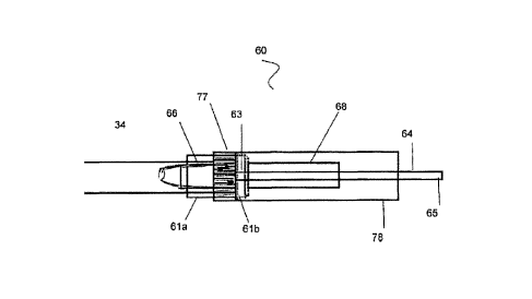
With reference to Fig. 4, the catheter connection system 60 of the present
invention
includes a retention collar 62, a cannula 64, a hollow elongated member 67,
and a sleeve 79.
The cannula 64 may be a tube of thin, somewhat flexible but strong wall
construction.
The cannula 64 generally defines the longitudinal axis of the present
invention and extends to
approximately the center of the invention. One end (proximal) of the cannula
64 fixedly attaches
to the hollow elongated member 67, which in turn is removable attached to the
drainage tube 30.
The hollow elongated member 67 has a lower or first tapered portion 66 and an
upper or
second portion 68. Between the lower 66 and upper 68 portions two spaced apart
ridges 71a,b.
When assembled, the hollow elongated member extends through the retention
collar 62 that sits
in the space 73 between the two ridges 71a,b. The two ridges 71a,b prevent the
collar 62 from
leaving the space 73. The hollow elongated member 67 may be made of a rigid
construction.
8
CA 2995280 2018-02-15
The tapered portion 66 of the hollow elongated member 67 fits snugly within
the drainage tube
30. The lower tapered portion 66 tapers from the ride 71a and reaches its
narrowest diameter at
slightly less than the diameter of the drainage tube.
The upper portion 68 has an outer diameter that is similar to that of the
distal portion of
seal sealing valve, and an inner diameter that is slightly larger than the
outer diameter of the
cannula 64. The upper portion 68 of the elongated member 67 is generally
coaxial with cannula
64, which passes through the upper portion 68 spaced away from the inner walls
of the upper
portion 68. The cannula 64 has a first proximal portion 63 that is housed
within the upper
portion 68, and a second distal portion 65 that extends beyond the upper
portion 68. The length
of the second portion 65 is enough to pass into the passageway of the valve
feature and open the
one-way valve.
The collar 62 may be made of a rigid construction. The collar 62 is coaxial
with the
hollow elongated member, which passes through the bore of the collar 62. The
collar 62
includes two portions: a proximal portion 61a and a distal portion 61b. The
distal portion 61b of
the collar sits within space 73. The inner diameter of the distal portion is
slightly larger than the
diameter of space 73, but smaller than ridges 71a,b.
The inner diameter of the proximal portion 61a is larger than the outer
diameter of the
drainage tube 30. The inner walls of the distal portion 61a may include one or
more ridges that
extend from the inner wall.
Sleeve 79 is a hollow flexible tube coaxial with the upper portion 68 of
elongated
member 67, which in turn is coaxial with the cannula 64. Sleeve 79 include a
proximal end 77
and a distal end 78. The proximal end 77 has an inner diameter that is
slightly bigger than the
outer diameter of distal portion 61b of collar 62, such as when assembled, the
proximal end 77
frictionally receives the distal portion 61b. The inner wall of proximal end
77 of sleeve 79
includes one or more ridges. The inner diameter at this ridges is slightly
larger than the outer
diameter of the upper portion 68 of the elongated member 67, but slightly
smaller than the outer
diameter of ridge 71a. As such, when assembled, the inner ridges of the
proximal end 77
frictionally attach the sleeve 79 to the upper portion 68, while the proximal
end 77 frictionally
9
CA 2995280 2018-02-15
receives and attaches to the distal portion 61b of collar 62.
The outer diameter of the distal end 78 of the sleeve 79 is slightly larger
than the outer
diameter of the proximal portion 24 of the valve feature 20, but equal or
slightly smaller than the
outer diameter of the proximal end 29a of the distal portion 25 of valve
feature 20.
The length between the proximal end 77 of sleeve 79 and the distal end 78 of
sleeve 79
covers the upper (distal) portion 68 of hollow elongated member 67 and a
portion of the cannula
64 that extends beyond (i.e. that is not covered by) the distal portion 68 of
the elongated member
67.
The connector system 60 of the present invention may also include a protective
cover 80
for covering the sleeve 79 and the cannula 64. The protective cover 80 may
include a thread
designed to engage matching threads in the inner or outer wall of collar 62.
When assembled to the valve feature 20, the cannula 64 enters through the hole
in the end
26 of proximal portion 24, through passageway 28, though valve 72, thereby
opening valve 72.
The cannula 64 continues through passageway 28 until the end 69 of the distal
portion of the
hollow elongated member 67 abuts with the end 26 of valve feature 20.
Simultaneously, the
distal end 78 of the sealing sleeve 79 frictionally attaches to the outer wall
27 of the proximal
portion 24 and abuts to the proximal end 29a of the distal portion 25, thereby
sealing the
connection between the connection system 60 of the present invention and the
valve feature 20,
thereby allowing fluid removal from the pleural cavity into the vacuum source
50. Removal of
fluid can be discontinued by simply pulling the connection system 60 from the
valve feature 20
thereby disengaging the catheter 10 from the vacuum source 50.
The connector system of the present invention does not require an actual lock,
like those
of the prior art, but rather is dependent on the vacuum in the vacuum source
thereby creating the
seal and holding it in place. The outer cuff (sleeve 79), when inserted fully,
and vacuum is
introduced to the catheter for drainage, creates a "vacuum" seal, that keeps
the catheter in place.
The hollow elongated member also acts as a safety mechanism, protecting the
inner cannula that
opens the valve. This keeps the inner cannula in the optimum placement, to
keep the valve fully
CA 2995280 2018-02-15
opened. The hollow elongated member also ensures the inner cannula will not be
moved on an
angle either way, to prevent a change in flow, or damage to the valve or
cannula.
Through the embodiments that are illustrated and described, the currently
contemplated
best mode of making and using the invention is described. Without further
elaboration, it is
believed that one of ordinary skill in the art can, based on the description
presented herein, utilize
the present invention to the full extent.
Although the description above contains many specificities, these should not
be construed
as limiting the scope of the invention, but as merely providing illustrations
of some of the
presently embodiments of this invention.
II
CA 2995280 2018-02-15