Note: Descriptions are shown in the official language in which they were submitted.
CA 02995286 2018-02-09
WO 2017/024409
PCT/CA2016/050947
1
ELECTRIC MACHINE
TECHNICAL FIELD
[001] Electric machines.
BACKGROUND
[002] In the design of electric machines, it is known to select structural
parameters such as slot
number depending on the intended application and desired performance
characteristics of the
machine. However, not all values of the structural parameters are used in
practice. There is room
for improved performance of electric machines, particularly in robotics.
[003] Electric machines typically use electrically conductive wire turns
wrapped around soft
magnetic stator posts (teeth) to generate flux. The manufacturing process for
this type of motor
construction can be time consuming and expensive. As well, such motors
typically have a torque
to mass ratio that makes them relatively heavy for mobile actuator
applications such as in
robotics where the weight of a downstream actuator must be supported and
accelerated by an
upstream actuator.
SUMMARY
[004] The inventor has proposed an electric machine with a novel range of
structural
parameters particularly suited for robotics, along with additional novel
features of an electric
machine. The features for example relate to improved heat dissipation
resulting from the
structure of electromagnetic elements, to rigidity of the electric machine,
conductor design,
cooling, rotor design, stator design and operating parameters.
[005] In an embodiment, an electric machine comprises a first carrier having
an array of
electromagnetic elements and a second carrier having electromagnetic elements
defining
magnetic poles, the second carrier being arranged to move relative to the
first carrier. An airgap
is provided between the first carrier and the second carrier. The
electromagnetic elements of the
first carrier include posts, with slots between the posts, one or more
electric conductors in each
slot, the posts of the first carrier having a post height in mm. The first
carrier and the second
SUBSTITUTE SHEET (RULE 26)
CA 02995286 2018-02-09
WO 2017/024409 PCT/CA2016/050947
2
carrier together define a size of the electric machine. The magnetic poles
having a pole pitch in
mm. The size of the motor, pole pitch and post height are selected to fall
within a region in a
space defined by size, pole pitch and post height that provides a benefit in
terms of force or
torque per weight per excitation level. The electromagnetic elements defining
magnetic poles
may be permanent magnets. This embodiment can be applied to any of the
disclosed machines.
[006] In various embodiments, there may be included any one or more of the
following
features: the electric machine may be a radial flux machine, having an airgap
diameter, the size
of the electric machine being the airgap diameter. The electric machine may be
an axial flux
machine, having an average airgap diameter, the size of the electric machine
being the average
airgap diameter. The electric machine may be a linear machine having a
direction of translation,
the first carrier having a first length in the direction of translation, the
second carrier having a
second length in the direction of translation, the size of the electric
machine being the first length
if the first length is shorter or equal to the second length and the second
length if the second
length is shorter than the first length. The electric conductors may comprise
a concentrated
winding. The electric conductors may comprise a distributed winding. The first
carrier may
comprise a stator formed of a unitary piece of magnetically susceptible
material, each post
comprising a portion of the stator. The stator may comprise a material with no
measurable creep
below 20,000 psi. The stator may comprise a magnetically susceptible material.
The posts may
each have a tangential width and the stator may comprise a backiron portion,
the backiron
portion having a thickness equal to or less than the tangential width of the
posts. The second
carrier may comprise an annular disk formed of a unitary piece of a material
and defining an
axis, and having an inner edge and an outer edge, circumferentially spaced
second carrier posts
extending axially from the annular disk and defining second carrier slots
between the second
carrier posts, and the annular disk defining holes extending between the inner
edge and the outer
edge. The electric machine may have an axis defining an axial direction, the
second carrier
having an inner circumference and an outer circumference, the inner
circumference has an inner
axial length, the outer circumference has an outer axial length, and the inner
axial length may be
not equal to the outer axial length. The inner axial length may be less than
the outer axial length.
The second carrier may have a conical shape. The electric conductors may
comprise anodized
aluminum conductors. There may be a coolant supply connected to supply cooling
fluid to one or
both of the first carrier and the second carrier. There may be a power supply
connected to supply
SUBSTITUTE SHEET (RULE 26)
CA 02995286 2018-02-09
WO 2017/024409 PCT/CA2016/050947
3
electrical energy of at least 70A/mm2 to the electric conductors. The second
carrier may
comprise magnet slots and the electromagnetic elements of the second carrier
may comprise
permanent magnets held within the magnet slots by magnetic forces. The
electric conductors
may form single layers around the posts, measured radially outward from the
posts. The airgap
may be from 0.001" to 0.010-. The airgap may be from 0.005' to 0.010-. The
electric machine
may be mounted on a robotic arm. The components or the robotic arm may form a
housing for
the electric machine that supports the first carrier and the second carrier.
The electric machine
may be a transverse flux machine. The electric machine may be a frameless
electric machine.
[007] There is provided an electric motor comprising a stator comprising
electromagnetic
elements, the stator having posts on one side and a backiron having cooling
fins on an opposite
side, the stator comprising a unitary piece of material including at least
portions of the posts and
at least portions of the cooling fins. In various embodiments, there may be
included any one or
more of the following features: The posts may have a post width in the
circumferential direction,
and the backiron including the fins may have a height greater than 50% of the
post width. The
fins may have tips comprising a different material than the unitary piece of
material. The electric
motor may be an axial flux motor. The cooling fins may be spiral shaped. The
electric motor
may have a rotor having electromagnetic elements defining magnetic poles, the
rotor being
arranged to rotate relative to the stator, the magnetic poles having a pole
pitch S in mm, an airgap
between the stator and the rotor, posts of the stator having a post height in
mm, the stator and the
rotor together defining a size of the electric machine, the size of the motor,
pole pitch and post
height being selected to fall within a region in a space defined by size, pole
pitch and post height
that provides a benefit in terms of force or torque per weight per excitation
level.
[008] There is also provided an electric motor comprising a rotor arranged for
rotation relative
to one or more stators comprising electromagnetic elements, the rotor
comprising a permanent
magnet carrier loaded with permanent magnets, an output ring, and bearings for
supporting the
rotor for rotation, the bearings located intermediate between the permanent
magnet carrier and
the output ring. In various embodiments, there may be included any one or more
of the following
features: the motor may be an axial flux motor, and the one or more stators
may be two stators
and the rotor may be arranged between the two stators. The bearings may be
preloaded by
magnetic forces between the rotor and stators. The rotor may have two axial
sides, and comprises
SUBSTITUTE SHEET (RULE 26)
CA 02995286 2018-02-09
WO 2017/024409 PCT/CA2016/050947
4
=
magnets on each axial side of the rotor, the magnets on each axial side
oriented tangentially, and
each magnet aligned axially with a respective magnet on the other axial side,
the tangential
orientation of each magnet being opposite to the tangential orientation of the
respective magnet
on the other side. The one or more stators may comprise spiral cooling fins.
[009] There is also provided an electric motor comprising a rotor arranged on
bearings for
rotation between two stators from which the rotor is separated by airgaps, a
magnetic force
between the rotor and stators attracting the stators to the rotor and applying
a preloading force on
the bearings. In various embodiments, there may be included any one or more of
the following
features: the rotor may have an output ring located radially inward from the
magnets.
[010] The bearings may have outer diameter (OD) races attached to the rotor.
The rotor may
have an output ring located radially outward from the magnets. The bearings
may have inner
diameter (ID) races attached to the rotor. The airgaps may close by more than
50% as a result of
magnetic force if the bearings are not present in the assembly. The stators
and rotor may come
into contact if the bearings are not present in the assembly. There may be
axial inward facing
surfaces of a housing and the bearings may have axial outward facing bearing
races contacting
the axial inward facing surfaces of the housing, and the axial inward facing
surfaces of the
housing may deform under magnetic load such that the difference in position
between the
position of the axial inward facing surfaces and a hypothetical position of
the inward facing
surface if no bearings are present is greater than .002-.
[011] There is provided an electric machine comprising a first carrier having
an array of
electromagnetic elements, a second carrier having electromagnetic elements
defining magnetic
poles, the second carrier being arranged to move relative to the first
carrier, an airgap between
the first carrier and the second carrier, the electromagnetic elements of the
first carrier including
posts, with slots between the posts, the slots having one or more electric
conductors in each slot,
the second carrier comprising posts and at least a first retaining element for
the electromagnetic
elements defining magnetic poles, and the electromagnetic elements of the
second carrier having
a depth longer than a depth necessary to saturate the posts of the
electromagnetic elements of the
first carrier. In various embodiments, there may be included any one or more
of the following
features: the electromagnetic elements defining magnetic poles may comprise
permanent
magnets. The first retaining element may be a back iron. The first retaining
element may be a
SUBSTITUTE SHEET (RULE 26)
CA 02995286 2018-02-09
WO 2017/024409 PCT/CA2016/050947
side iron. The first retaining element may be an end iron. The posts of the
second carrier and the
first retaining element may be connected by a rigid connection. The posts,
first retaining element
and rigid connection may comprise an isotropic material. The rigid connection
may comprise
flux path restrictions. The first retaining element may comprise a homogenous
rigid element and
the posts may comprise homogenous extensions of the rigid element. The
permanent magnets
may each have a width, and the ratio of magnet depth to magnet width may be
greater than 2:1m
greater than 3:1, or greater than 4:1. The electromagnetic elements of the
first carrier and the
second carrier may be arranged so that a greater portion of magnetic flux
flows through the rigid
element than flows through the air gap. The permanent magnets may be retained
by magnetic
force. The permanent magnets may be tapered to narrow in a direction toward
the first carrier.
The posts of the second carrier may be tapered to narrow in a direction away
from the first
carrier. The posts of the second carrier may prevent the electromagnetic
elements of the second
carrier from moving in a direction towards of the first carrier. The second
carrier may comprise a
homogenous rigid element, and the posts of the second carrier may comprise
homogenous
extensions of the rigid element, the homogenous rigid element comprising flux
path restrictions.
The posts of the first carrier may have a post height in mm. the first carrier
and the second carrier
together may define a size of the electric machine, the magnetic poles may
have a pole pitch S in
mm, and the size of the motor, pole pitch and post height may be selected to
fall within a region
in a space defined by size, pole pitch and post height that provides a benefit
in terms of force or
torque per weight per excitation level.
[012] There is also provided an electric machine, comprising a first carrier
having an array of
electromagnetic elements, a second carrier having electromagnetic elements
defining magnetic
poles, the second carrier being arranged to move relative to the first
carrier, an airgap between
the first carrier and the second carrier, the electromagnctic elements of the
first carrier including
posts, with slots between the posts, the slots having one or more electric
conductors in each slot,
and the second carrier comprising a homogenous rigid element and posts. in
which the posts
comprise homogenous extensions of the rigid element, in which the posts of the
second carrier
comprises a relief to retain the electromagnetic elements of the second
carrier. In various
embodiments. there may be included any one or more of the following features:
the
electromagnetic elements of the second carrier may comprise first and second
ends, the first ends
facing towards the first carrier and the second ends facing away from the
first carrier, the second
SUBSTITUTE SHEET (RULE 26)
CA 02995286 2018-02-09
WO 2017/024409 PCT/CA2016/050947
6
ends being tapered. The posts of the first carrier have a post height in mm,
the first carrier and
the second carrier may together define a size of the electric machine, the
magnetic poles may
have a pole pitch S in mm, and the size of the motor, pole pitch and post
height may be selected
to fall within a region in a space defined by size, pole pitch and post height
that provides a
benefit in terms of force or torque per weight per excitation level.
[013] There is provided a rotor for an electric machine, the rotor comprising
an annular disk
formed of a unitary piece of a material and defining an axis, and having an
inner edge and an
outer edge, circumferentially spaced posts extending axially from the annular
disk and defining
slots between the posts and the annular disk defining holes extending radially
within the annular
disk from the inner edge or outer edge. In various embodiments, there may be
included any one
or more of the following features: the posts may be formed of the unitary
piece.
[014] The posts may be arranged on both sides of the annular disk. The posts
on each side of
the disk may be aligned with respective posts on an opposite side of the disk
as projected onto a
plane perpendicular to the axis. The holes may be aligned with the slots as
projected onto a plane
perpendicular to the axis. The holes may fully extend through the annular disk
between the inner
edge and the outer edge. The annular disk may define openings connecting the
holes with the
slots. Each post may extend between the inner edge and the outer edge. The
posts may have a
first axial height at the inner edge and a second axial height different from
the first axial height at
the outer edge. The second axial height may be greater than the first axial
height. The posts may
define straight lines between the inner edge and the outer edge, adjacent
posts defining
substantially parallel lines. The posts may have an inverse taper of
circumferential thickness with
axial height for retaining magnets. There may be an electric machine
comprising the rotor and
further comprising a stator having an array of electromagnetic elements, the
rotor having
electromagnetic elements defining magnetic poles, the rotor being arranged to
move relative to
the stator, an airgap between the stator and the rotor, the electromagnetic
elements of the stator
including stator posts, with slots between the stator posts, one or more
electric conductors in
each slot, the stator posts having a post height in mm, the stator and the
rotor together defining a
size of the electric machine, the magnetic poles having a pole pitch S in mm,
the size of the
motor, pole pitch and post height being selected to fall within a region in a
space defined by size,
pole pitch and post height that provides a benefit in terms of force or torque
per weight per
excitation level.
SUBSTITUTE SHEET (RULE 26)
CA 02995286 2018-02-09
WO 2017/024409 PCT/CA2016/050947
7
[015] There is provided a rotor for an electric machine, the rotor comprising:
an inner rotor
portion comprising outwardly projecting members; an outer rotor portion
comprising inwardly
projecting members: the outer rotor portion being arranged around the inner
rotor portion so that
the inwardly projecting members and outwardly projecting members are
interdigitated; and
permanent magnets arranged between the interdigitatcd inwardly projecting
members and
outwardly projecting members so that the inwardly projecting members and
outwardly projecting
members provide flux paths for the permanent magnets.
[016] In an embodiment the inwardly projecting members arc regularly spaced
and the
outwardly projecting members are regularly spaced.
[017] There is provided a stator for an electric machine, the stator
comprising circumferentially
spaced posts defining slots between the posts, conductive elements arranged
around the posts.
and each conductive element defining a respective electrical flow path that
extends through a
respective selection of the slots in order of circumferential arrangement of
the slots of the
respective selection of slots, and extending alternately inward and outward
through successive
slots of the respective selection of slots.
[018] In various embodiments, there may be included any one or more of the
following
features: the respective selections of slots may each consist of all slots in
a respective sector of
the stator. The respective selections of slots may each exclude every third
slot in a respective
sector of the stator. The conductive elements may be spaced from at least a
segment of the radial
end portions of the posts to define axial flow paths adjacent to the radial
end portions of the
posts. It may be the case that at least some of the conductive elements are
spaced
circumferentially from at least some posts that define slots through which the
at least some of the
conductive elements extend. There may be electrical connections between
axially adjacent
conductor elements to serially connect the electrical flow paths of the
axially adjacent conductor
elements. It may be the case that at least for some conductive element, the
conductive element
has an end turn and a slot turn and the end turn is wider than the slot turn.
It may be the case that
at least some of the conductive elements have uniform width around the end
turn. The
conductive elements rnay form single layers around the posts, measured
radially outward from
the posts. The posts may have a post height in mm, and the electric machine
may further
comprise a rotor having electromagnetic elements defining magnetic poles. the
second carrier
being arranged to move relative to the stator, an airgap between the stator
and the rotor, the stator
SUBSTITUTE SHEET (RULE 26)
CA 02995286 2018-02-09
WO 2017/024409 PCT/CA2016/050947
8
and the rotor together defining a size of the electric machine, the magnetic
poles having a pole
pitch S in mm, the size of the motor, pole pitch and post height being
selected to fall within a
region in a space defined by size, pole pitch and post height that provides a
benefit in terms of
force or torque per weight per excitation level.
[019] There is provided an electric machine comprising a first carrier having
an array of
electromagnetic elements; a second carrier having electromagnetic elements
defining magnetic
poles, the second carrier being arranged to move relative to the first
carrier; an airgap between
the first carrier and the second carrier, and the electromagnetic elements of
the first carrier
comprise posts, with slots between the posts. in which one or more slots are
without an electric
conductor at a level in the one or more slots corresponding to a location of
an electric conductor
in an adjacent slot and form conduits, and the conduits are connected to a
source of cooling fluid.
[020] There is provided an electric machine, comprising a first carrier having
electromagnetic
elements, a second carrier having electromagnetic elements defining magnetic
poles, the second
carrier being arranged to move relative to the first carrier, an airgap
between the first carrier and
the second carrier, and the electromagnetic elements of the first carrier
including a plurality of
electric conductor layers, the electric conductor layers being formed of
anodized aluminum
conductors having corner gaps, the corner gaps being coated with a coating. In
various
embodiments, there may be included any one or more of the following features:
the coating may
be a dielectric coating. The coating may be a polymeric coating. The coating
may be a varnish.
Each electric conductor layer may further comprise a pair of contact tabs. The
pair of contact
tabs may comprise aluminum. The anodized aluminum conductors may also have one
or more
surfaces and the surfaces may also be coated with the coating. The electric
machine may
comprise an axial flux machine. The electric machine may comprise a radial
flux machine. The
electric machine may comprise a transverse flux machine. The electromagnetic
elements of the
first carrier may include posts, with slots between the posts, one or more of
the electric conductor
layers arranged through each slot, the posts of the first carrier having a
post height in mm, the
first carrier and the second carrier together defining a size of the electric
machine, the magnetic
poles having a pole pitch S in mm, and the size of the motor, pole pitch and
post height being
selected to fall within a region in a space defined by size, pole pitch and
post height that provides
a benefit in terms of force or torque per weight per excitation level.
SUBSTITUTE SHEET (RULE 26)
CA 02995286 2018-02-09
WO 2017/024409 PCT/CA2016/050947
9
[021] There is also provided an electric conductor for an electric machine,
the electric
conductor comprising first and second contact tabs, a hard-anodized aluminum
surface, an
aluminum conducting path, and a coating.
[022] In various embodiments, there may be included any one or more of the
following
features: the coating may be a dielectric coating. The coating may be a
polymeric coating. The
coating may be a varnish. The coating may fill corner gaps in the hard-
anodized aluminum
surface. The first and second contact tabs may comprise aluminum.
[023] There is also provided a method of producing aluminum conductors for an
electric
machine, each aluminum conductor comprising first and second contact tabs, a
surface, and a
conducting path, the method comprising hard anodizing the surface of the
aluminum conductors,
applying a liquid or powder coating to the surface of the aluminum conductors,
and baking the
liquid or powder coating. In various embodiments, there may be included any
one or more of
the following features: there may be an additional step of masking the first
and second contact
tabs. The liquid or powder coating comprises a polymeric liquid or powder
coating. The
polymeric coating may comprise a liquid or powder epoxy coating. The polymeric
coating may
comprise a dielectric polymeric coating. The epoxy coating may be a liquid
epoxy coating and
the method may further comprise the step of curing the epoxy coating to a B
state. Where the
epoxy coating is cured to a B state there may be included steps of stacking
the aluminum
conductors, welding together the first contact tabs. and welding together the
second contact tabs.
The step of baking the liquid coating may comprise baking a stack of aluminum
conductors.
There may be an additional step of directing liquid coating into edge gaps in
the aluminum
conductor. Where the step of stacking the aluminum conductors has occurred,
and the coating is
a liquid coating, additional steps may be taken of separating one or more
layers of the stack of
aluminum conductors by inserting one or more spacers between layers, and
removing the spacers
from the stack of aluminum conductors after baking the liquid coating. The
coating may be a
powder coating and the method may further comprise the step of partially
hardening the powder
coating. Where the powder coating is partially hardened there may be included
steps of stacking
the aluminum conductors, welding together the first contact tabs, and welding
together the
second contact tabs. The step of baking the powder coating may comprise baking
a stack of
aluminum conductors. The coating may be a powder coating and the step of
applying a powder
coating may comprise spraying the aluminum conductor with an oppositely
charged powder. The
SUBSTITUTE SHEET (RULE 26)
CA 02995286 2018-02-09
WO 2017/024409 PCT/CA2016/050947
coating may be a powder coating and the step of applying a powder coating may
comprise
dipping the aluminum conductor into a fluidizcd bed of oppositely charged
dielectric powder.
Where the step of stacking the aluminum conductors has occurred, and the
coating is a powder
coating, additional steps may be taken of placing spacers separating one or
more layers of the
stack of aluminum conductors with one or more spacers, and removing the
spacers from the
stack of aluminum conductors after baking the powder coating. A layer of a
second coating may
also be applied to the surface of the aluminum conductors.
[024] There is provided an electric machine comprising a first outer carrier
comprising
electromagnetic elements, a second outer carrier comprising electromagnetic
elements, an inner
carrier comprising electromagnetic elements and disposed between the first
outer carrier and the
second outer carrier, either the inner carrier or both the first outer carrier
and the second outer
carrier defining magnetic poles, a spacer element fixedly connecting the first
outer carrier to the
second outer carrier, and bushings or low friction coatings disposed between
the inner carrier and
the first and second outer carriers, and between the inner carrier and the
spacer element, for
supporting the inner carrier for movement relative to the first outer carrier
and the second outer
carrier.
[025] In various embodiments, there may be included any one or more of the
following
features: the inner carrier may define magnetic poles and the first outer
carrier and the second
outer carrier may each comprise a unitary piece of material on which the
electromagnetic
elements of the respective carriers are supported. The first outer carrier and
the second outer
carrier may define magnetic poles and the inner carrier may comprise a unitary
piece of material
on which the electromagnetic elements of the inner carrier are supported. The
first outer carrier
and the second outer carrier may be preformed of a shape such that in use they
bend toward the
inner carrier under the influence of magnetic attraction to the inner carrier,
but do not exert a
substantial force on the bushings or low friction coatings disposed between
the inner carrier and
the first and second outer carriers. The magnetic poles may have a pole pitch
S in mm, the first
outer carrier, second outer carrier and inner carrier together defining a size
of the electric
machine, the inner carrier defining the magnetic poles, and the
electromagnetic elements of the
first and second outer carriers including posts, with slots between the posts,
one or more electric
conductors in each slot, the posts having a post height in mm, or the first
and second outer
carriers defining the magnetic poles, the electromagnetic elements of the
inner carrier including
SUBSTITUTE SHEET (RULE 26)
CA 02995286 2018-02-09
WO 2017/024409 PCT/CA2016/050947
11
posts, with slots between the posts, one or more electric conductors in each
slot, the posts having
a post height in mm, the size of the motor, pole pitch and post height being
selected to fall within
a region in a space defined by size, pole pitch and post height that provides
a benefit in terms of
force or torque per weight per excitation level.
[026] These and other aspects of the device and method are set out in the
claims.
BRIEF DESCRIPTION OF THE FIGURES
[027] Embodiments will now be described with reference to the figures. in
which like reference
characters denote like elements, by way of example, and in which:
[028] Fig. I is a CAD model of a complete exemplary actuator prototype.
10291 Fig. 2 is a section view of the exemplary actuator in Fig. 1.
[030] Fig. 3 shows a side view detail of the stator and rotor of the exemplary
actuator in Fig. I.
1031] Fig. 4 shows a schematic of the entire stator and rotor of the exemplary
actuator in Fig. I.
[032] Fig. 5 shows a simplified schematic section view of the stator and rotor
of the exemplary
actuator in Fig. 1, with schematic CAD model coils on the posts.
[033] Fig. 6 shows a non-limiting simplified exemplary embodiment of a stator
of a linear
electric machine.
[034] Fig. 7 shows an isometric view of the stator in Fig. 6.
[035] Fig. 8 shows a top view of the stator in Fig. 6 and Fig. 7 with the
upper insulator layer
removed.
[036] Fig. 9 shows top view of the stator in Fig. 8 with the two upper phase
circuits removed.
[037] Fig. 10 is a sectional view of the stator of Fig. 6 to Fig. 9.
[038] Fig. 11 is a detail view of the cross section shown in Fig. 10.
[039] Fig. 12 shows an isometric view of a non-limiting exemplary linear
electric machine.
SUBSTITUTE SHEET (RULE 26)
CA 02995286 2018-02-09
WO 2017/024409 PCT/CA2016/050947
12
[040] Fig. 13 shows the electric machine of Fig. 12 with internal lines.
[041] Fig. 14 shows the electric machine of Fig. 12 with the upper permanent
magnet carrier
backiron removed.
[042] Fig. 15 shows the electric machine of Fig. 14 with upper permanent
magnet carrier plate
and most of the upper permanent magnets removed.
[043] Fig. 16 shows the electric machine of Fig. 15 with all permanent magnets
removed and
the top insulator plate removed.
[044] Fig. 17 shows the electric machine of Fig. 16 with the electrical
connectors removed and
the top spacer layer removed.
[045] Fig. 18 shows the electric machine of Fig. 17 with the top phase circuit
conductor
removed and the second insulator layer removed.
[046] Fig. 19 shows the electric machine of Fig. 18 with the second spacer
layer removed and
most of the posts removed.
[047] Fig. 20 shows the electric machine of Fig. 19 with the upper air core
sensor, the second
phase circuit, the structural cylindrical spacers, and the rest of the posts
removed.
[048] Fig. 21 shows the electric machine of Fig. 20 with the third phase
circuit and the bottom
spacer layer removed.
[049] Fig. 22 shows the conductor circuits, posts, and potting compound ring
for a non-limiting
exemplary embodiment of an axial flux, rotary stator electric machine.
[050] Fig. 23 shows a detail view of the stator in Fig. 22.
[051] Fig. 24 an axial flux, rotary stator with three phases and one conductor
circuit per phase,
with the potting compound ring removed.
[052] Fig. 25 is an isometric view of three phase circuits with soft magnetic
material posts
positioned by the aluminum circuits during assembly.
[053] Fig. 26 is an exploded view of Fig. 25.
SUBSTITUTE SHEET (RULE 26)
CA 02995286 2018-02-09
WO 2017/024409 PCT/CA2016/050947
13
[054] Fig. 27 is a closeup of an individual layer of the embodiment of Fig. 25
and Fig. 26.
[055] Fig. 28 is a closeup of an individual layer of the embodiment of Fig. 25
and Fig. 26.
[056] Fig. 29 is a top view detail of a single stator circuit.
[057] Fig. 30 shows sections of an axial flux electric machine.
[058] Fig. 31 shows an array of electromagnetic elements (here, coils) in a
linear electric
machine facing electromagnetic elements (here, permanent magnets) across an
airgap.
[059] Fig. 32 illustrates a sectioned axial flux electric machine with a load
arm.
[060] Fig. 33 shows a stator of an axial flux electric machine;
[061] Fig. 34 is detail of the stator of Fig. 33.
[062] Fig. 35 is detail of electric conductor layers for use in the stator of
Fig. 33.
[063] Fig. 36 is further detail of electric conductor layers for use in the
stator of Fig. 33.
[064] Fig. 37 is further detail of an electric conductor layer for use in the
stator of Fig. 33.
[065] Fig. 38 shows electric conductor layers of the stator of Fig. 33.
[066] Fig. 39 shows electric conductor layers of the stator of Fig. 33.
[067] Fig. 40 shows an embodiment of robotic arms that may be equipped at the
joints with an
embodiment of the disclosed electric machine.
[068] Fig. 41 shows an embodiment of robotic arms that may be equipped at the
joints with an
embodiment of the disclosed electric machine.
[069] Fig. 42 shows a magnet configuration for an embodiment of the disclosed
electric
machine.
[070] Fig. 43 is a first figure of detail showing successive layers of a
linear electric machine.
[071] Fig. 44 is a second figure of detail showing successive layers of a
linear electric machine.
[072] Fig. 45 is a third figure of detail showing successive layers of a
linear electric machine.
SUBSTITUTE SHEET (RULE 26)
CA 02995286 2018-02-09
WO 2017/024409 PCT/CA2016/050947
14
[073] Fig. 46 is a fourth figure of detail showing successive layers of a
linear electric machine.
[074] Fig. 47 shows details of connections for connecting layers of a linear
electric machine to
a multiphase source of electric excitation
[075] Fig. 48 shows details of connections for connecting layers of a linear
electric machine to
a multiphase source of electric excitation
[076] Fig. 49 is a first figure showing successive layers of an embodiment of
a liner electric
machine.
[077] Fig. 50 is a second figure showing successive layers of an embodiment of
a liner electric
machine.
[078] Fig. 51 is a third figure showing successive layers of an embodiment of
a liner electric
machine.
[079] Fig. 52 is a fourth figure showing successive layers of an embodiment of
a liner electric
machine.
[080] Fig. 53 shows an embodiment of an electric machine with coils in both
rotor and stator.
[081] Fig. 54 shows an embodiment of an electric machine with coils in both
rotor and stator.
[082] Fig. 55 shows an embodiment of an electric machine with a Hallbach array
of magnets.
[083] Fig. 56 shows a cross-section of an exemplary actuator assembly with a
two-part stator,
three phases and a 3:2 stator post : permanent magnet ratio.
[084] Fig. 57 shows a detailed cross-section view of the embodiment from Fig.
56.
[085] Fig. 58 shows the torque plotted as a function of rotor position for a
3:2 ratio or stator
posts : permanent magnets, demonstrating the effect of rotating one stator
relative to the other.
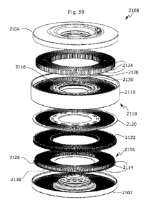
[086] Fig. 59 shows an exploded view of the exemplary embodiment in Fig. 56.
[087] Fig. 60 shows a cross section of a partially exploded view of the
exemplary embodiment
in Fig. 56.
[088] Fig. 61 show a section detail view of a housing of the exemplary
embodiment in Fig. 56.
SUBSTITUTE SHEET (RULE 26)
CA 02995286 2018-02-09
WO 2017/024409 PCT/CA2016/050947
[089] Fig. 62 shows a section of an assembled housing and stator of the
exemplary embodiment
in Fig. 56.
[090] Fig. 63 shows a section of an assembled housing and stator of the
exemplary embodiment
in Fig. 56 with the first conductor layer on the stator.
[091] Fig. 64 shows a plan view of the section in Fig. 63.
[092] Fig. 65 shows four conductor layers of the same phase from the exemplary
embodiment
in Fig. 56.
[093] Fig. 66 shows the arrangement of three adjacent conductor layers from
different phases
from the exemplary embodiment in Fig. 56.
[094] Fig. 67 shows a section of an assembled housing and stator from the
exemplary
embodiment in Fig. 56with radial fluid flow channels between conductors
indicated.
[095] Fig. 68 shows a plan view of the radial, axial and circumferential fluid
flow paths for
cooling fluid between the conductors of the exemplary embodiment in Fig. 56.
[096] Fig. 69 shows a section view through the stator of Fig. 68showing the
cooling fluid flow
path.
[097] Fig. 70 shows a cross-sectional view of an exemplary embodiment with two
stators and a
rotor.
[098] Fig. 71 shows a stator from the exemplary embodiment in Fig. 70 with
conductors shown
in one section.
[099] Fig. 72 shows a section view of a simplified stator with conductors.
[100] Fig. 73 shows an exemplary configuration of conductors on a stator in
which the
conductors do not skip slots.
[101] Fig. 74 shows an exemplary configuration of conductors on a stator in
which some
conductors with variable conductor widths.
[102] Fig. 75 shows an exploded view of four layers of conductors from Fig.
74.
SUBSTITUTE SHEET (RULE 26)
CA 02995286 2018-02-09
WO 2017/024409 PCT/CA2016/050947
16
[103] Fig. 76 shows an exemplary configuration of conductors with multi-layer
thickness fluid
flow gaps.
[104] Fig. 77 shows a configuration of conductor layers in an exemplary method
of assembly.
[105] Fig. 78 shows an exemplary configuration of conductors without radial
fluid flow gaps.
[106] Fig. 79 shows an exemplary embodiment of a stator with curved, variable-
width posts.
[107] Fig. 80 shows an exemplary embodiment of a rotor with tangentially
oriented permanent
magnets and radially extending flux path members.
[108] Fig. 81 shows a detail view of the rotor in Fig. 80.
[109] Fig. 82 shows the structural connection between the inward members and
inner part of
the rotor in Fig. 80.
[110] Fig. 83 shows the structural connection between the outward members and
outer part of
the rotor in Fig. 80.
11 1 1] Fig. 84 shows a detail view of the rotor in Fig. 80 with the magnets
removed.
[112] Fig. 85 shows an expanded view of the rotor in Fig. 80 reflecting an
exemplary method of
assembly.
[113] Fig. 86 shows a view of the rotor in Fig. 60 with the inner rotor ring
and outwardly
projecting flux members shown in black.
[114] Fig. 87 shows an exemplary embodiment of a rotor comprising two axial
halves and
tapered magnets.
[115] Fig. 88 shows a section view of the rotor in Fig. 87.
[1161 Fig. 89 shows an exploded view of the rotor in Fig. 87.
[117] Fig. 90 shows the plane view of the magnets in the rotor in Fig. 87,
showing the polarity
of the magnets.
[118] Fig. 91 shows the structural connection between the outward members and
outer part of
the rotor in Fig. 87.
SUBSTITUTE SHEET (RULE 26)
CA 02995286 2018-02-09
WO 2017/024409
PCT/CA2016/050947
17
[119] Fig. 92 shows the rotor in Fig. 87 with an external ring holding the
rotor halves together.
[120] Fig. 93 shows an exploded view of an exemplary embodiment comprising two
rotor
halves and two stator halves.
[121] Fig. 94 shows a cross-section view of the embodiment in Fig. 93.
[[22] Fig. 95 shows a stator in the embodiment shown in Fig. 93.
[123] Fig. 96 shows an exploded view of the stators and baseplate of the
embodiment in Fig.
93.
[124] Fig. 97 shows a section view of the embodiment in Fig. 93.
[125] Fig. 98 shows a cross-section view of an exemplary embodiment with two
rotor halves
and one stator.
[126] Fig. 99 shows a section view of the exemplary embodiment in Fig. 98.
[127] Fig. 100 shows an exemplary configuration of a robotic arm having a
series of electric
machines acting as actuators and being spaced along the arm.
[128] Fig. 101 shows a mounting configuration for an electric machine on a
robotic arm.
[129] Fig. 102 shows an embodiment of a rotor configuration.
[130] Fig. 103 shows an exemplary configuration of a laminated post stator.
[131] Fig. 104 shows a section view of an exemplary embodiment of a stator
with radially
aligned post laminations.
[132] Fig. 105 shows an exemplary embodiment of a laminated post construction
with posts
extending through the backiron, with tapered barbs as mechanical pull-out
stops.
[133] Fig. 106 is a section view of the embodiment shown in Fig. 105.
[134] Fig. 107 is a section view of the embodiment shown in Fig. 105, showing
the pattern of
insulation between laminations and a portion of the resulting magnetic flux
path.
[135] Fig. 108 is a schematic drawing showing the effect of anodizing a sharp
edge.
SUBSTITUTE SHEET (RULE 26)
CA 02995286 2018-02-09
WO 2017/024409
PCT/CA2016/050947
18
[136] Fig. 109 is a schematic drawing of a stator section comprising
conductors with rounded
edges.
[137] Fig. HO is a schematic drawing of a stator section comprising conductors
with sharp
edges.
[138] Fig. 111 is a perspective view of two adjacent layers of stackable flat
conductors shown
side by side before assembly.
[139] Fig. 112 is a schematic drawing showing an example of a coated
conductor, with
dielectric coating over the surface of an anodized conductor
[140] Fig. 113 is a closeup of a corner of the conductor of Fig. 112.
[141] Fig. 114 is a perspective view showing conductors stacked together into
layers with the
conductor pair stacked between stator posts.
[142] Fig. 115 is a schematic drawing showing an example of a coated
conductor, with
complete coverage of the gaps at the sharp edges.
[143] Fig. 116 is a schematic drawing showing an example of a coated
conductor, with more
than complete coverage of the gaps at the sharp edges.
[144] Fig. 117 is a schematic drawing showing an example of a coated conductor
of Fig. 115,
coated with a further polymer layer.
[145] Fig. 118 shows a section view of an assembled stator and conductors with
a spacer
between one or more conductor layers in one or more slots
[146) Fig. 119 shows a section view of the conductors and spacers before
spacer removal with
the powder edge coating contacting and adhering the conductors to each and/or
to the post
sidewalls.
[147] Fig. 120 shows a simplified section of stator with a spacer component
being removed.
[148] Fig. 121 shows a method of making anodized conductors;
[149] Fig. 122 shows a further detail of a method of making anodized
conductors;
SUBSTITUTE SHEET (RULE 26)
CA 02995286 2018-02-09
WO 2017/024409 PCT/CA2016/050947
19
[150] Fig. 123 shows a cross-section of an embodiment of a conical rotor;
[151] Fig. 124 shows a close-up cross-sectional view of the embodiment in Fig.
123;
[152] Fig. 125 shows a close-up cross-sectional view of the embodiment in Fig.
123;
[153] Fig. 126 shows a close-up cross-sectional view of the embodiment in Fig.
123;
[154] Fig. 127 shows a close-up cross-sectional view of the embodiment in Fig.
123;
[155] Fig. 128 is an axial view of an embodiment of an assembled actuator
including power and
encoder connectors.
[156] Fig. 129 is a section view of the actuator of Fig. 128 showing an
internal rotor along a
centre plane between two stators.
[157] Fig. 130 is an isometric section view of a stator and housing assembly
of the actuator of
Fig. 128 with a partial section of layered conductors.
[158] Fig. 131 is an axial view of a stator, inner housing, outer housing, and
layered conductors
of the actuator or Fig. 128.
[159] Fig. 132 is an isometric view of rotor components of the embodiment of
Fig. 128.
[160] Fig. 133 is a side view of a rotor and stators with an example magnet
arrangement in
which adjacent magnets are oppositely tangentially polarized.
[[61] Fig. 134 is a perspective view of an actuator including a separation
member to separate
two stators.
[162] Fig. 135 is another section view of the stator for the actuator of Fig.
128, showing a
magnetic flux path through cooling tins.
[163] Fig. 136 is a section view of a stator with cooling fins showing a cross
sectional area for
flux linkage at a diagonal between posts.
[164] Fig. 137 is a simplified section view of a stator with circumferential
cooling fins.
[165] Fig. 138 is a section view of an actuator including a separation member
configured to
reduce preload on inner bearings.
SUBSTITUTE SHEET (RULE 26)
CA 02995286 2018-02-09
WO 2017/024409 PCT/CA2016/050947
[166] Fig. 139 is a section view of an actuator including a separation member
configured to
enhance preload on inner bearings.
[167] Fig. 140 is a cross sectional view of an actuator having sealed cooling
channels.
[168] Fig. 140A is a perspective view of an embodiment having semi-circular
cooling channels.
[169] Fig. 140B is a cross-section view of an embodiment with two stators and
a rotor, with a
housing connected by an inner diameter rigid connection.
[170] Fig. 140C is an expanded cross-section view of the embodiment shown in
Fig. 140B.
[171] Fig. 141 is a simplified section view of a linear embodiment of a
concentrated flux rotor.
[172] Fig. 142 is a model of a concentrated flux rotor with back iron showing
magnetic flux
lines.
[173] Fig. 143 is a model of a concentrated flux rotor with back iron showing
magnetic flux
lines, further showing component lengths.
[174] Fig. 144 is a cross-section through a segment of an axial flux
concentrated flux rotor with
tapered magnets and flux path restrictions.
[175] Fig. 145 is a close-up section view of a portion of an axial flux
conccntratcd flux rotor
with extended length magnets.
[176] Fig. 146 is a simplified angled cross-section of an embodiment of a
radial flux
concentrated flux rotor with stator.
[177] Fig. 147 is a simplified section view of the radial flux concentrated
flux rotor and stator
shown in Fig. 146.
[178] Fig. 148 is a simplified angled cross-section of the concentrated flux
rotor shown in Fig.
146, further showing mills.
[179] Fig. 149 is a model of a concentrated flux rotor with back iron with
variant geometries
and showing magnetic flux lines.
SUBSTITUTE SHEET (RULE 26)
CA 02995286 2018-02-09
WO 2017/024409 PCT/CA2016/050947
21
[180] Fig. 150 is a simplified angled cross-section of an embodiment of a
radial flux
concentrated flux rotor with rotor reliefs and tapered rotor ends.
[181] Fig. 151 is a simplified exploded section view of an embodiment of an
axial flux stator-
rotor-stator configuration of a concentrated flux rotor with end iron.
[182] Fig. 152 is a simplified exploded section view of an embodiment of an
axial flux stator-
rotor-stator configuration of a concentrated flux rotor with back iron, end
iron and flux path
restrictions.
[183] Fig. 153 is a simplified exploded section view of an embodiment of an
axial flux rotor-
stator-rotor configuration of a concentrated flux rotor with end irons and
flux path restrictions.
[184] Fig. 154 is a simplified exploded section view of an embodiment of an
axial flux rotor-
stator-rotor configuration of a concentrated flux rotor with end irons, flux
path restrictions and
back irons.
[185] Fig. 155 is a simplified exploded section view of an embodiment of a
trapezoidal stator-
rotor-stator configuration of a concentrated flux rotor with back irons and
end irons.
[186] Fig. 156 is simplified exploded section view of the embodiment shown in
Fig. 155
without back irons.
[187] Fig. 157 is a simplified exploded section view of an embodiment of a
trapezoidal rotor-
stator-rotor configuration of a concentrated flux rotor with end irons.
[188] Fig. 158 is a simplified exploded section view of the embodiment shown
in Fig. 157 with
back irons and without end irons.
[189] Fig. 159 is a simplified perspective view of an embodiment of a rotor-
stator-rotor
configuration linear flux machine with back irons and end irons.
[190] Fig. 160 is a simplified perspective view of the embodiment shown in
Fig. 159 without
back irons.
[191] Fig. 161 is a simplified perspective view of an embodiment of a stator-
rotor-stator
configuration of a linear flux machine with back iron.
SUBSTITUTE SHEET (RULE 26)
CA 02995286 2018-02-09
WO 2017/024409 PCT/CA2016/050947
22
[1921 Fig. 162 is a simplified perspective view of an embodiment of a stator-
rotor-stator
configuration of a linear flux machine with end irons, showing an angled cross-
section of the
rotor.
[193] Fig. 163 is a model of an axial motor concentrated flux rotor with
interrupted rotor posts.
[194] Fig. 164 is the model of an axial motor concentrated flux rotor shown in
Fig. 164 with
magnetic flux lines shown.
[195] Fig. 165 is a cross-section of an embodiment of a transverse flux
machine in which flux
links across the air gap in the radial direction.
[196] Fig. 166A is a perspective view of the stator of the embodiment of a
transverse flux
machine shown in Fig. 165.
[197] Fig. 166B is a perspective view of an upper portion of the rotor of the
embodiment of a
transverse flux machine shown in Fig. 165.
[198] Fig. 167 is a cross-section of an embodiment of a transverse flux
machine in which flux
links across air gaps in the axial direction.
[199] Fig. 168 is a perspective view of a stator section of the embodiment of
a transverse flux
machine shown in Fig. 167
[200] Fig. 169 is a cross-section of an upper portion of the rotor of the
embodiment of a
transverse flux machine shown in Fig. 168.
[201] Fig. 170A shows a graph of torque at constant current density for a
simulated series of
motors differing in slot pitch and post height.
[202] Fig. 170B shows the highest stator current density possible at a given
temperature for a
simulated series of motors differing in slot pitch and post height.
[203] Fig. 170C shows constant temperature torque as a function of slot pitch
and post height
for a series of electric machines.
SUBSTITUTE SHEET (RULE 26)
CA 02995286 2018-02-09
WO 2017/024409 PCT/CA2016/050947
23
[204] Fig. 170D shows the value of a weighting function for at the highest
stator current density
possible at a given temperature for a simulated series of motors differing in
slot pitch and post
height.
[205] Fig. 170E shows Km" for a simulated series of motors differing in slot
pitch and post
height, for a fixed current density.
[206] Fig. 170F shows KR" for a simulated series of motors differing in slot
pitch and post
height, for a fixed current density.
[207] Fig. 171 shows the region of benefit for KR", with respect to the rest
of the geometries in
the domain, for a machine with 200 mm size and a boundary line for KR" > 1.3
[208] Fig. 172 shows the region of benefit for KR", with respect to the rest
of the geometries in
the domain, for a machine with 200 mm size and a boundary line for KR" > 1.5
[209] Fig. 173 shows the region of benefit for KR", with respect to the rest
of the geometries in
the domain, for a machine with 200 mm size and a boundary line for KR" > 1.8
[210] Fig. 174 shows the region of benefit for KR", with respect to the rest
of the geometries in
the domain, for a machine with 100 mm size and a boundary line for KR" > 1.5
[211] Fig. 175 shows the region of benefit for KR", with respect to the rest
of the geometries in
the domain, for a machine with 100 mm size and a boundary line for KR" > 1.7
[212] Fig. 176 shows the region of benefit for KR", with respect to the rest
of the geometries in
the domain, for a machine with 100 mm size and a boundary line for KR" > 1.9
[213] Fig. 177 shows the region of benefit for KR", with respect to the rest
of the geometries in
the domain, for a machine with 50 mm size and a boundary line for KR" > 2.2
[214] Fig. 178 shows the region of benefit for KR", with respect to the rest
of the geometries in
the domain, for a machine with 50 mm size and a boundary line for KR" > 2.5
[215] Fig. 179 shows the region of benefit for KR", with respect to the rest
of the geometries in
the domain, for a machine with 50 mm size and a boundary line for KR" > 2.9
SUBSTITUTE SHEET (RULE 26)
CA 02995286 2018-02-09
WO 2017/024409
PCT/CA2016/050947
24
[216] Fig. 180 shows the region of benefit for KR", with respect to the rest
of the geometries in
the domain, for a machine with 25 mm size and a boundary line for KR" > 3.3
[217] Fig. 181 shows the region of benefit for KR", with respect to the rest
of the geometries in
the domain, for a machine with 25 mm size and a boundary line for KR" > 3.4
[218] Fig. 182 shows the region of benefit for KR", with respect to the rest
of the geometries in
the domain, for a machine with 25 mm size and a boundary line for KR" > 3.6
[219] Fig. 183 is a graph showing the sum of the eddy current and hysteresis
losses for a motor
series across a range of slot pitches at a rotor speed of 200 rpm with no
current applied.
[220] Fig. 184 is a graph showing torque for 24 slot laminated M- 19 and solid
M- 19 stators
with an applied current density of 6A/mm2.
[221] Fig. 185 is a graph showing individual and total stator losses fora 24
slot solid M-I 9
stator;
[222] Fig. 186 is a graph showing individual and total stator losses fora 108
slot solid M-I 9
stator.
[223] Fig. 187 is a graph showing torque for a 108-slot durabar, laminated M-
19 and solid M-
19 stators with an applied current density of 19.7A/mm2.
[224] Fig. 188 is a graph showing a torque-to-weight comparison for various
motors in a
simulation in which very strong NdFeB N52 permanent magnets were used in the
rotor.
[225] Fig. I 89 is a graph showing a torque comparison for various motors.
[226] Fig. 190 is a graph showing a stator loss comparison for various motors.
[227] Fig. 191 shows a method of cooling an actuator via a flow channel.
[228] Fig. 192 is a section view of an embodiment of an actuator assembly.
[229] Fig. 193A is a closeup section view of the actuator assembly of Fig.
192.
[230] Fig. 193B is a further closeup of bushings or low friction coating in
the section view of
the actuator assembly of Fig. I 93A.
SUBSTITUTE SHEET (RULE 26)
CA 02995286 2018-02-09
WO 2017/024409 PCT/CA2016/050947
[231] Fig. 194 is a section view of a stator and fixed ring of the actuator
assembly of Fig. 192.
[232] Fig. 195 is a closeup view of an embodiment of a stator for the actuator
assembly of Fig.
192, the arrows indicate how the conductors can be place onto the posts over
top of the
extensions.
[233] Fig. 196 is a closeup section view of the actuator assembly of Fig. 192
with one stator
and the corresponding bushings or low friction coating removed.
[234] Fig. 197 is a section view of a permanent magnet carrier for the
actuator assembly of Fig.
192.
[235] Fig. 198 is a closeup section view of a rotor and stator of the actuator
assembly of Fig.
192.
[236] Fig. I 99A is an axial isometric view of stator and rotor posts of the
actuator assembly of
Fig. 192.
[237] Fig. 199B is a further closeup of stator and rotor posts of the actuator
assembly of Fig.
199A.
[238] Fig. 200 shows the joint of a robot arm using a frameless motor/actuator
[239] Fig. 201 displays a cross-sectional view of the frameless motor/actuator
and robot arm
[240] Fig. 202 shows a close up of the section view of the frameless
motor/actuator stator, rotor
and housing assembly
[241] Fig. 203 shows an exploded view of the frameless motor/actuator robot
arm assembly
[242] Fig. 204 displays a section view through the housing to view the stator
and tab features
on the rotor Fig. 205 outlines the up, over and down assembly motion used with
the tab features
to secure the rotor
[243] Fig. 206 shows a close up of the section view displaying the tab feature
used to secure the
rotor
[244] Fig. 207 shows a section view through the housing to display the tab
features used on the
stator to secure the stator
SUBSTITUTE SHEET (RULE 26)
CA 02995286 2018-02-09
WO 2017/024409 PCT/CA2016/050947
26
DETAILED DESCRIPTION
[245] Immaterial modifications may be made to the embodiments described here
without
departing from what is covered by the claims. In the claims, the word -
comprising" is used in its
inclusive sense and does not exclude other elements being present. The
indefinite articles "a" and
-an" before a claim feature do not exclude more than one of the feature being
present. Each one
of the individual features described here may be used in one or more
embodiments and is not, by
virtue only of being described here, to be construed as essential to all
embodiments as defined by
the claims.
DEFINITIONS
[246] Several terms to be used throughout the text will first be defined.
[247] A carrier, as used here in the context of electric machines, may
comprise a stator or a
rotor when referring to rotary machines.
1248] A rotor as used herein may be circular. A rotor may also refer the
armature or reaction
rail of a linear motor. A stator may be circular. It may also refer to the
armature or reaction rail
of a linear motor.
[249] Teeth may be referred to as posts.
[250] In an electric motor, either a stator or rotor may have a commutated
electromagnet array
defined by coils wrapped around posts, while the other of the stator or rotor
may have magnetic
poles defined by permanent magnets or coils or both coils and permanent
magnets.
[251] Permanent magnets may be used in combinations with electromagnets on the
rotor and/or
stator to add flux to the system. PM means permanent magnet. EM means
electromagnet.
[252] Electromagnetic elements may comprise permanent magnets, posts (teeth),
slots defined
by magnetic posts, which may be soft magnetic posts, and electrical
conductors. In any
embodiment where one carrier has slots and posts, the other may have permanent
magnets for the
electromagnetic elements, and for any such embodiment, the term
electromagnetic element may
be replaced by the term permanent magnet. Magnetic poles in some cases, for
example in a
concentrated flux rotor embodiment, may be defined by permanent magnets in
conjunction with
adjacent posts in which a magnetic field is established by the permanent
magnets.
SUBSTITUTE SHEET (RULE 26)
CA 02995286 2018-02-09
WO 2017/024409 PCT/CA2016/050947
27
[253] Unless otherwise specified, "flux- refers to magnetic flux.
[254] A fractional slot motor is a motor with a fractional number of slots per
pole per phase. If
the number of slots is divided by the number of magnets, and divided again by
the number of
phases and the result is not an integer, then the motor is a fractional slot
motor.
[255] A carrier may be supported for motion relative to another carrier by a
frame or bearings,
and the bearings may be sliding, roller, fluid, air or magnetic bearings. An
axial electric machine
is an electric machine in which magnetic flux linkage occurs across an axial
airgap, and the
carriers are in the form of discs mounted coaxially side by side. A first
carrier can be arranged to
move relative to another carrier by either carrier being supported by a frame,
housing or other
element, while the other carrier moves relative the first carrier.
[256] A radial electric machine is an electric machine where the airgap is
oriented such that
magnetic flux is radially oriented, and the carriers are mounted
concentrically, one outside the
other. A linear actuator is comparable in construction to a section of an
axial flux or radial flux
rotary motor where the direction of motion is a straight line rather than a
curved path.
[257] A trapezoidal electric machine is an electric machine that is a
combination of both an
axial and radial flux machines, where the plane of the airgap lies at an angle
partway between the
planes formed by the airgaps in the axial and radial configurations.
[258] The airgap diameter for a rotary machine is defined as the diameter
perpendicular to the
axis of rotation at the centre of the airgap surface. In radial flux motors,
all of the airgap resides
at the same diameter. If the airgap surface is a disc-shaped slice as in axial
flux motors, the
average airgap diameter is the average of the inner and outer diameter. For
other airgap surfaces
such as a diagonal or curved surfaces, the average airgap diameter can be
found as the average
airgap diameter of the cross-sectional airgap view.
[259] For a radial flux motor, the airgap diameter refers to the average of
the rotor inner
diameter and stator outer diameter (for an outer rotor radial flux motor) or
the average of the
rotor airgap outer diameter and stator airgap inner diameter (for an inner
rotor radial flux motor).
Analogues of the airgap diameter of a radial flux motor may be used for other
types of rotary
motors. For an axial flux machine, the airgap diameter is defined as the
average of the PM inner
diameter and PM outer diameter and EM inner diameter and EM outer diameter.
SUBSTITUTE SHEET (RULE 26)
CA 02995286 2018-02-09
WO 2017/024409 PCT/CA2016/050947
28
[260] Size of an electric machine means the airgap diameter of an axial flux
machine or radial
flux machine as defined herein or the length in the direction of translation
of the carriers of a
linear machine. For linear machines where one carrier is longer than another,
then the length is
the length of the shorter carrier. For use with reference to the boundary
inequalities, the size of a
rotary machine is given in terms of diameter, but for a linear machine it is
the length that
corresponds to a circumference of a rotary machine. Therefore, the size X of a
linear motor that
corresponds in the equations to a rotary motor of size Y is related to Y as
X=pi*Y. This size of
any rotary electric machine for the purpose of the disclosed range, as a
general principle and
including transverse flux machines, is defined as the average of the largest
and smallest
diameters defined by the magnetically active airgap when it is projected onto
the plane that is
perpendicular to the axis of rotation
[261] The back surface of the stator is defined as the surface on the opposite
side of the stator to
the surface which is at the magnetically active airgap. In a radial flux
motor, this would
correspond to either the inner surface of the stator for an outer rotor
configuration, or the outer
diameter surface of the stator for an inner rotor configuration. In an axial
flux motor, the back
surface of the stator is the axially outer surface of the stator.
[262] Km is defined as the stall torque divided by the square root of the
electrical resistive
losses of a motor. In this patent document, it is proposed to assess motor
performance using Km
divided by the active magnetic mass of the motor, referred to in this
disclosure as KR or KR. The
active magnetic mass consists of the rotor and stator mass including magnets,
coils, teeth, and
backiron as is commonly reported by the manufacturers of frameless motors. The
KR metric may
be useful in assessing motor performance for applications where a low motor
mass is beneficial
to overall power consumption, such as robotics. In some cases, size-
independent analogues of
Km and KR, namely K." and KR" are used throughout the text. The conversion
between the
size-dependent and size-independent metrics is:
Km" firL D312
= ______________________________________
2
and
SUBSTITUTE SHEET (RULE 26)
CA 02995286 2018-02-09
WO 2017/024409 PCT/CA2016/050947
29
KR = _____________________________ 2 ,
where D is the average airgap diameter and L is the radial tooth length. For a
given size of
motor. D and L are taken to be fixed in the analysis, therefore KR or Km will
be proportional to
KR" or K. Consequently, statements relating to trends in KR will, in general,
implicitly be held to
apply to K; as well.
[263] Slot density is the number of slots divided by the circumferential
length of machine at the
average airgap diameter. If the pitch of the slots varies, the average slot
density of a device will
be used. Slot density can also be represented by the inverse of the slot
pitch. It is a measure of
how many slots occur per mm of circumferential length along the airgap at the
airgap diameter
(or its analogue). For rotary motors, it has the following equation:
N,
Slot density = _________________________
in/AG
where Ns is the number of slots, and DAG is the diameter of the airgap. For
the case of a linear
motor, the denominator of this function would be replaced by the length of the
carrier along the
direction of translation.
[264] Pole density is the number of poles divided by the circumferential
length of machine at
the average airgap diameter. If the pitch of the poles varies, the average
pole density of a device
will be used. Pole density can also be represented by the inverse of the pole
pitch. The pole pitch
is defined as the average distance at the average airgap between the center of
a PM pole of one
polarity to the center of the next PM pole on the same carrier having the
opposite polarity,
measured along the direction of motion. In rotary motors this distance is a
circumferential pitch
measured at the average airgap diameter, DAG. It is a measure of how many
poles occur per
mm of circumferential length along the airgap at the airgap diameter (or its
analogue). For rotary
motors, it has the following equation:
Np
Pole density =
ThuAG
SUBSTITUTE SHEET (RULE 26)
CA 02995286 2018-02-09
WO 2017/024409 PCT/CA2016/050947
where Np is the number of poles, and DAG is the diameter of the airgap. For
the case of a linear
motor, the denominator of this function would be replaced by the length of the
carrier along the
direction of translation.
[265] For distributed windings, the number of slots will be N x the number of
poles where N is
a multiple of the number of phases. So for a 3 phase machine N could be 3, 6,
9, 12, etc. For
concentrated windings, the number of slots can vary but must be a multiple of
the number of
phases. It does not depend on the number of poles, except that certain
combinations of slots and
poles will yield higher torque and better noise-reduction or cogging-reduction
characteristics.
The minimum number of slots for a given number of poles should not be below
50% to obtain
adequate torque.
[266] Conductor volume may be used to refer to the slot area per length of a
single stator. The
slot area is the area of a cross-section of a slot in the plane which is
orthogonal to the teeth but
not parallel to the plane of relative motion of the carriers. In an axial
motor, this plane would be
perpendicular to a radius passing through the slot. The slot area effectively
defines the
maximum conductor volume that can be incorporated into a stator design, and it
is usually a goal
of motor designers to have as high a fill factor as possible to utilize all
the available space for
conductors.
[267] Since maximum conductor volume in a stator is defined in terms of slot
area, any stator
referred to as having a maximum conductor volume or slot area must have slots
and teeth to
define the slots. This parameter is defined for rotary motors as:
NA
Slot area per length = S = slot density = As
IrDAG
where As is the cross-sectional area of a single slot, or the average area of
a single slot for stator
designs that have varying slot areas.
[268] As a relatively accurate approximation, As may be calculated as the
height of the tooth,
hi. multiplied by the average width of the slot, w, such that the equation
above becomes:
hIshtws
Slot area per length = _____________ = slot density = kw,
TrDAG
[269] These definitions are size-independent. They can be used to characterize
any motor.
SUBSTITUTE SHEET (RULE 26)
CA 02995286 2018-02-09
WO 2017/024409 PCT/CA2016/050947
31
[270] Pole pitch and tooth height may be used to define a specific stator or
rotor geometry.
Since the parameters are size-independent, measures of benefit disclosed
herein are likewise
size-independent, being written in terms of force per area and force per mass,
where mass refers
to the mass of the stator and rotor including any magnets and coils, such that
the torque and
torque per mass for any size rotary motor can be found by an appropriate
multiplication factor
containing the radius at the airgap. For any two motors of the same airgap
diameter, the graphs
will have the same contours for torque as for force/area, and for torque
density as for force/mass.
[271] A cooling channel is any structure that defines a flow path for cooling
fluid, including gas
flow or liquid flow, such as passages defined by fins, or unoccupied spaces in
slots, or conduits
through or around a structure.
[272] Slot depth or post height may also be used as a proxy for the conductor
volume. The post
height, also known as the tooth height or slot depth, is a proxy for the
amount of cross-sectional
area in a slot available for conductors to occupy. Although the slots may have
a variety of shapes
such as curved or tapered profiles, the slot height is based upon the closest
rectangular
approximation which best represents the total area of the slot which may be
occupied by
conductors. This dimension does not include features such as pole shoes which
add to the height
of the tooth without adding substantially to the slot area. For transverse
flux motors, the post
height is defined as the portion of the post which is directly adjacent to the
conductor coil,
perpendicular to the direction of the coil windings.
[273] A motor series is a set of motor geometries represented by analysis that
have the same
construction and winding but with one or two differences such as, a range of
pole pitches, or a
range of post heights.
[274] Number of rotor poles is equal to the number of regions of alternating
polarity magnetic
flux across the airgap. For example, in a surface permanent magnet rotor, the
number of poles is
determined by the number of alternating polarity permanent magnets. However.
poles may also
be created by groups of magnets such as in a 11albach array, by
electromagnets, or by
combinations of electromagnets and permanent magnets. A conductor layer is an
electrical
conductor formed as a unit that establishes a conductive path that does not
intersect itself when
the conductor is viewed in plan view. The conductor layer may thus be placed
directly around
SUBSTITUTE SHEET (RULE 26)
CA 02995286 2018-02-09
WO 2017/024409 PCT/CA2016/050947
32
posts with minimal or no plastic deformation of the layer. Each conductor
layer occupies a
different part of slots at different levels of the slots, for example
corresponding to different axial
positions in an axial flux machine or different radial positions in a radial
flux machine. In some
embodiments, a conductor layer may be made of a material with sufficient
rigidity that it can be
placed over posts and into slots as a unit, without being individually
helically wound on to the
posts.
[275] A continuous stall torque of a direct drive motor is the continuous
torque output at zero
speed where the produced heat and dissipated heat reach equilibrium for a
given cooling means
that is at the maximum allowable electrical conductor temperature.
[276] A concentrated winding comprises individually wound posts or any winding
configuration that results in the alternating polarity of adjacent posts when
energized. It is
understood that not all posts will be the opposite polarity of both adjacent
posts at all times.
However, a concentrated winding configuration will result in the majority of
the posts being the
opposite polarity to one or both adjacent posts for the majority of the time
when the motor is
energized. A concentrated winding is a form of fractional slot winding where
the ratio of slots
per poles per phase is less than one.
[277] The term 'solid stator' refers to a homogenous magnetically susceptible
support structure
functioning as a stator of an electric machine.
EXEMPLARY RADIAL FLUX ELECTRIC MACHINE
[278] Fig. 1 shows a CAD model of a complete exemplary actuator 1010 prototype
with an
outer housing 1012 and an inner housing 1014. The inner housing 1014 is the
fixed (or
reference) member, and the outer housing 1012 is the rotating member. Housings
can be made of
any rigid material such as, but not limited to aluminum, steel or plastic. The
exemplary actuator
1010 comprises a bearing/seal 1016 and output mounting holes 1018. The
prototype shown in
Fig. 1 has produced a high torque to weight ratio. This is important for
applications such as, but
not limited to. robotics. The design shown in Fig. 1 has slot density and post
height that comes
within the definition of slot density and post height that is believed to
provide a benefit in terms
of KR, thus being especially suitable for use in robotics applications.
SUBSTITUTE SHEET (RULE 26)
CA 02995286 2018-02-09
WO 2017/024409 PCT/CA2016/050947
33
1279] Fig. 2 shows a section view of the same exemplary actuator 1010 with an
internal stator
1020 attached to the inner housing 1014 and an external rotor 1022 attached to
the outer housing
1012. The rotor 1022 comprises permanent magnets 1024 attached to a rotor yoke
1026. The
stator 1020 comprises stator teeth 1028 attached to a stator yoke 1030. The
stator 1020 is made
of a soft magnetic material such as but not limited to laminated electrical
steel. Solid material
can be used for the stator 1020 such as but not limited to powdered soft
magnetic materials that
exhibit reduced eddy currents and/or reduced hysteresis. Due to the unusually
thin flux path
cross section of this device which will reduce eddy current losses, solid
steel or iron may be used
for the stator 1020 with acceptable performance in certain lower speed
applications. The section
view in Fig. 2 shows simplified bearings 1016 and no coils on the stator 1020.
[280] Fig. 3 shows a side view detail of the stator 1020 and rotor 1022 (no
coils shown in this
figure for clarity of illustration). Fig. 4 shows a schematic of the entire
stator 1020 and rotor
1022 with permanent magnets 1024 on the rotor 1022 but no coils on the stator
2010.
[281] With a slot density in the range of 0.16 to 0.5 and higher, for example,
and considering
that it is not unusual for a slot to be about as wide as a tooth, tooth width
can be in the order of
2 mm for a 200 mm wide machine. Wider or narrower teeth can be used. An
advantage of
thinner teeth is that solid materials may be used with minimal eddy currents
due to the teeth
being closer to the thickness of normal motor laminations. A common motor
lamination can be
in the range of 0.015" to 0.025". This prototype has performed satisfactorily
with a hot rolled
steel core. This has advantages for low cost manufacturing. Other advantages
of using a solid
core include the possibility of higher flux densities in materials like iron.
Permanent magnets
1024 may be adhered to a soft magnetic material rotor 1022. Spacers 1025,
shown in Fig. 3, in
the rotor 1022 are not necessary but may be used to ensure the magnets 1024
are assembled at
the correct spacing.
[282] Fig. 1 to Fig. 5 show a non-limiting example of a 4:3 post 1028 to PM
1024 ratio
according to the principles disclosed here for a four phase configuration. In
general, for n phases,
there may be a ratio of posts to poles of n:n-1, where the number of poles may
be the number of
permanent magnets. A 3:2 ratio may be used (with three phases), or possibly a
2:1 (with two
phases) ratio or a 5:4 ratio (with five phases) or a 6:5 ratio (with six
phases) or a 7:6 ratio (with
seven phases) and so on. 4:3 has shown to be a ratio which produces high
torque and is used as a
SUBSTITUTE SHEET (RULE 26)
CA 02995286 2018-02-09
WO 2017/024409 PCT/CA2016/050947
34
non-limiting example here. Or there may be n phases, with a ratio of posts to
poles of n:n +1.
Many other post-to-PM ratios and combinations are possible and can be used
according to the
principles of this device.
[283] The embodiment of Fig. Ito Fig. 5 has 172 posts, but an electric machine
with the
proposed slot density may have greater or smaller number of posts. A minimum
number of posts
may be 100 posts to obtain sufficient torque density for some robotic
applications. Fig. 5 shows
a simplified schematic section view of the stator 1020 and rotor 1022 with
schematic CAD
model coils 1032 on the posts.
[284] For a 4 phase configuration of an electric machine as disclosed, the
number of posts may
be divisible by 8, with a ratio of 4 posts to 3 permanent magnets. The
permanent magnets may be
arranged with an alternating radial polarity.
[285] A high number of posts allows fewer windings per post. In a non-limiting
exemplary
embodiment, the windings on each posts are only one layer thick (measured
circumferentially,
outward from the post). This reduces the number of airgaps and/or potting
compound gaps
and/or wire insulation layers that heat from the conductors must conduct
through for the
conductors to dissipate heat conductively to the stator posts. This has
benefits for heat capacity
(for momentary high current events) and for continuous operation cooling. When
direct cooling
of the coils by means of gas or liquid coolant in direct contact with the
conductors, a low number
of circumferential layers, and for example a single circumferential layer of
wire on a post,
combined with high slot density, results in a very high surface area of the
conductors (relative to
the volume of the conductors) exposed to the cooling fluid. This is beneficial
for cooling the
conductors and is one of many exemplary ways to take advantage of low
conductor volume of an
embodiment of an electric machine. A single row (or low number of rows) of
coils per posts also
reduces manufacturing complexity allowing for lower cost production. In
another embodiment,
the windings of each post are two layers thick.
EXEMPLARY LINEAR ELECTRIC MACHINE
[286] In an embodiment, such as shown in Fig. 6. an electric machine may be
built with a
stratified construction which allows main components to be fabricated from,
for example, sheet
stock of conductor material such as, but not limited to, copper, and insulator
materials such as,
SUBSTITUTE SHEET (RULE 26)
CA 02995286 2018-02-09
WO 2017/024409 PCT/CA2016/050947
but not limited to, hard anodized aluminum, with high speed and low cost
manufacturing
processes such as, but not limited to, stamping or fine blanking. Instead of
winding conductor
wires around posts. the conductor circuits may be stamped and then assembled
in layers. If
insulator layers are used alternately with each conductor layer, thc conductor
layers may, in some
configurations, be assembled without insulation coating. Alternately,
conductor circuit layers can
be coated with insulation before assembly for additional insulation
effectiveness, or to eliminate
the need for separate insulating layers.
[287] Insulating layers can be of many different types of material. Aluminum
is a material
which can be stamped or fine blanked and then hard anodized. Hard anodized
aluminum
provides high voltage insulation and excellent heat conduction away from
conductors. It also
provides excellent structural integrity. Conductor and insulating layers can
be fixed together with
a number of possible adherents including but not limited to, epoxy, potting
compounds,
thermally activated adhesives, and thermoplastic adhesives.
[288] Non-electrically conductive (or insulated electrically conductive)
materials may be used
on the same strata as the conductive layers to provide structural integrity
and heat
sink/dissipation qualities. These non-filled layers in the slots between
conductor layers can also
be used to provide a flow path for a cooling gas or liquid so that the open
slots form conduits.
Cooling fluid may also be used as an air or liquid bearing medium. Many
different materials may
be used for spacer layers including, but not limited to anodized aluminum,
Torlon TM (a reaction
product of trimellitic anhydride and aromatic diamines), phenolic, or a
composite material such
as, but not limited to a metal matrix composite.
[289] Each conductor may be a layer. Layers may be made up of one or more
sections. A
scction can be, for example, an entire length of a linear motor, or a complete
circumference of a
rotary motor, or it can be two or more lengthwise sections of a linear motor
or two or more
angular sections of a rotary motor. Each layer in each section may be a
conductor circuit for only
one phase. In a common electrical machine with wire windings, the conductor
wire is helically
wound and overlaps other wire in that phase and/or wire from other phases.
This type of 3-
dimensional wire winding configuration cannot be fabricated with a single
layer per phase
because a simple layered assembly does not allow the interwoven or helically
overlapping
construction that typical post winding requires.
SUBSTITUTE SHEET (RULE 26)
CA 02995286 2018-02-09
WO 2017/024409 PCT/CA2016/050947
36
[290] A wiring may be used to create a poly-phase motor with each adjacent
slot comprising
conductors from a different phase or different combination of phases than an
adjacent slot. This
has a number of advantages which include simplified manufacturing for reduced
cost and the
ability to provide very effective cooling as described below.
[291] The conductor manufacturing methods disclosed arc especially effective
in constructing
devices with high slot density, as they may replace high precision wire
winding.
[292] A single layer per phase winding in an embodiment may provide a
conductor in two
adjacent slots and then skipping one or more slots (depending on the number of
phases, for
example) such that a layer exists in two adjacent slots followed by one or
more slots with no
conductors on that layer from that phase. Thus, in an electric machine where
electromagnetic
elements of a carrier comprise posts, with slots between the posts, one or
more slots are without
an electric conductor at a level in the one or more slots corresponding to a
location of an electric
conductor in an adjacent slot.
CONDUCTOR LAYERS WITII OPENINGS
[293] In some embodiments, the disclosed electric machine not only provides a
high cross
sectional area for fluid flow, it provides a consistently distributed airflow
channel pattern which
ensures that every conductor is in contact with the cooling fluid for close to
half of its length. In
other words, in an embodiment, there are never more than two layers of
conductor layers
contacting at a time. The sequence vertically in a slot may be for example
conductor ¨ conductor
¨ space - conductor ¨ conductor ¨ space - conductor ¨ conductor ¨ space. This
means that one
side of all conductors is always in contact with the fluid in the cooling
channels that is created by
the missing conductor. This evenly distributed cooling channel array assists
in achieving
sufficient heat dissipation to compensate for the higher heat production that
results from a
reduced conductor volume.
[294] Some embodiments of an effective cooling channel spacing pattern include
overlap of the
end turns of a conductor combined with offset of the phases combined with a
gap at the end of
each of the posts to allow tangential airflow at the end of each post. With
these details, the
airgaps are consistent, fewer (larger) channels are avoided, the conductor
surface area is
increased and are no stagnant airgaps due to no post-end tangential conduit.
SUBSTITUTE SHEET (RULE 26)
CA 02995286 2018-02-09
WO 2017/024409 PCT/CA2016/050947
37
[295] In an embodiment, there may be two slots in a row with a conductor from
a phase
followed by p minus 2 slots with no conductor from any phase on that layer
(with p being the
number of phases). For three phases that would be two slots with a conductor
from a phase
followed by one slot with no conductor from that, or any other, phase. With
four phases it would
be two slots in a row with a conductor from a phase followed by two slots with
no conductor
from that, or any other phase on that layer, and so on. No conductor from that
or any other phase
means there is an air space or a space that can be filled with potting
compound and/or a filler
material such as a heat extracting insert.
[296] With a three phase configuration, as a non-limiting example, two
adjacent slots will have
a single layer with a conductor from a first phase in a first and second slot
followed by a third
slot which will not have a conductor on that layer. This pattern repeats to
provide a single layer
of winding to provide a conductor on both circumferential sides for every
first of three posts. On
another layer, a second phase circuit exists on a single layer and has a
conductor from this
second phase in the second and third slot followed by a slot that will not
have a conductor from
any phase on that layer. A third phase is on another separate layer with
conductors in every third
and first slot but no conductor from any layer in every second slot.
[297] A layered construction permits scalable construction from micro/MEMS
motors all the
way up to motors that are 10 meters or more in diameter. Layered construction
allows
components to be deposited with additive manufacturing processes, or to be
assembled with each
conductor and/or insulator component and/or spacer layer being pre-fabricated
from a single or
multiple parts.
[298] This winding configuration may be done with a bendable wire conductor on
each layer
(which is only helically wound on two posts to connect to the next layer, tbr
a non-limiting
example). Or this conductor configuration can be assembled from pre-fabricated
conductor
layers so that little or no bending of the conductors is required during
construction and assembly.
[299] Skipping slots has the perceived detriment of reduced slot fill
percentage. However, this
missing conductor in periodic slots can be used as a cooling channel to allow
direct cooling of a
high percentage of the surface area of the conductors and/or insulating layers
and/or EM posts.
SUBSTITUTE SHEET (RULE 26)
CA 02995286 2018-02-09
WO 2017/024409 PCT/CA2016/050947
38
The cooling channel or conduit may be provided with a flow of coolant. The
missing conductor
in periodic slots can be used as an air channel so as to reduce the weight of
the device.
[300] The ability to form the conductors before assembly and to not require
bending of the
conductors, is also suited to the use of super conductors which are typically
less malleable than
copper wire. The high surface area that is available for coolant contact is
also suited to the use of
superconductors to keep the conductors below the necessary temperature for
super conductivity,
if using DC currents and superconductors. The use of low temperature coolant
can also make
conventional conductors like copper and aluminum more efficient by reducing
their electrical
resistance. Embodiments of the layered conductors are also suited to
maintaining copper or other
conductor materials at an artificially low temperature for increased
efficiency in certain
applications.
STATOR OF LINEAR ELECTRIC MACHINE
[301] A non-limiting simplified exemplary embodiment of a stator 1058 of a
linear electric
machine is shown in Fig. 6. The design shown in Fig. 6 may comprise an upper
insulating layer
1034, a lower insulating layer 1034, and a stack of conductor layers 1040,
1042 and 1044.
Various numbers of conductor layers may be used. Posts 1036 may extend through
openings
1035 in the insulating layers 1034. Connections 1046 may be provided to a
source of electrical
excitation. For each layer 1040, 1042, 1044. a separate layer may be provided.
[302] The simple construction of the stator 1058 is evident from the low
number of easily
manufactured components. An insulating layer 1034 can be made of a non-
electrically
conductive material or insulated electrically conductive material and may be
for example made
of hard anodized aluminum. It may be punched or fine blanked, and then
chemical etched to
remove sharp edges (important to achieve high insulating values at edges when
hard anodized)
and then hard anodized. The layer 1034 is, in this non-limiting exemplary
embodiment, 0.5 mm
thick, but the electric machine of Fig. 6 can have a range of dimensions. The
insulating layer
1034 has rectangular cut-outs 1035 for the EM posts 1036 (although other
shapes for posts 1036
and post cut-outs 1035 can be used with various effects, and serves to
precisely position the posts
1036 during assembly). If the insulating layers 1034 are electrically
conductive (even if they
have an insulated coating) it is important, for some applications, that there
be no electrical
SUBSTITUTE SHEET (RULE 26)
CA 02995286 2018-02-09
WO 2017/024409 PCT/CA2016/050947
39
connection around any single post within the either layer 1034. For this
reason, a cut 1038 is
provided between each slot to break potential eddy current circuit. This slot
can be punched or
blanked or cut at different points in the process. such as with a laser
before, during, or after
assembly. The minimum thickness of an electric conductor may be >75% of the
maximum
thickness of the conductor layer. The minimum thickness of the electric
conductor may be >50%
of the maximum thickness of the conductor layer. This allows for punching and
minimal
thinning of the conductors at cross-over points. The >50% provides for the
gaps to still be
necessary. The method of manufacture may comprise punching or stamping a
conductor layer
from a constant thickness material and placing the conductor layer into the
slots. The resulting
conductor layer may have a variable thickness.
[303] The EM posts 1036 may be made of a soft magnetic material such as but
not limited to,
steel or powdered iron or other type of soft magnetic material. The conductors
1040, 1042, and
1044 may be made of copper (or possibly aluminum or super conductors for some
applications)
and can be formed or punched or fine-blanked and then coated with an
insulating layer (not
shown) such as, but not limited to, coatings that are common to wire
conductors. Surface
connection vias 1046 are assembled with the rest of the layers or are drilled
and added afterward,
if needed.
[304] The stator 1058 is assembled by hand or machine, and then may be clamped
between two
flat surfaces and potted with a potting compound. During the potting process,
the top and bottom
mold plates can be retracted enough to allow wetting of all surfaces before
being brought axially
together again into contact or close proximity. The lengths of the posts 1036
may be used to
position the upper and lower potting mold parts (not shown).
[305] If internal cooling is desired, the potting compound is removed from the
open slot
sections such as by allowing gravity to remove potting compound from the large
gaps. or by
pushing air through the device to push the potting compound out of the
cavities.
[306] Fig. 7 shows an isometric view of the stator 1058 in Fig. 6 (with no
potting compound or
insulating layer shown on the conductors). This non-limiting exemplary
embodiment has one
conductor per phase per section (which is the complete linear actuator stator
1058, in this
example.) Multiple conductor layers of the same phase can be used in a stator
section.
SUBSTITUTE SHEET (RULE 26)
CA 02995286 2018-02-09
WO 2017/024409 PCT/CA2016/050947
[307] Fig. 8 shows a top view of the stator 1058 in the non-limiting exemplary
embodiment of
Fig. 6 and Fig. 7 with the upper insulator layer 1034 removed, revealing how
each of the phase
circuits 1040, 1042, and 1044 is a single component (and in this case, having
identical geometry)
that nearly encircles every first, second, or third of three consecutive posts
1036. Phase circuits
1040, 1042. and 1044 correspond to phases one, two, and three, respectively.
[308] Fig. 9 shows phase circuits 1042, and 1044 removed so the circuit shape
of phase 1040
can be clearly seen to nearly encircle every third of three consecutive posts
1036 by filling the
slot 1037 on either side of every third post 1036. and to skip every first
slot 1037. The other two
phase circuits skip a different slot 1037 and nearly encircle a different post
1036.
[309] Fig. 10 is a sectional view of the non-limiting exemplary stator 1058 of
Fig. 6 to Fig. 9.
It shows how a conductor is missing from one out of every three consecutive
slots 1037 in each
conductor layer 1040, 1042, and 1044. Fig. 11 is a detail view of the cross
section shown in Fig.
10.
[310] Layers can be bonded together or fused together or soldered together. If
some internal
layers, such as but not limited to the copper layers and spacer layers between
the anodized
aluminum or other separator layers, are tinned, and if all components or their
coatings are
bondable by a given solder compound, the parts can be assembled and then
heated under
pressure in an oven to fuse everything together. It is important, if pre-
tinning with solder is used,
that the separation layers are not coated so there is no conductor layer-to-
layer conductivity.
Alternatively, a thermoplastic resin can be used to coat the parts and they
can then be assembled
and heated in an oven under enough pressure to ensure the correct axial and
other dimensions.
An epoxy or other hardening adhesive can be used during or after assembly to
adhere and pot the
components. If airflow channels are included in the design, potting can be
followed by blowing
the adhesive out of the large chambers before the epoxy hardens. An advantage
of a pre-preg or
solder tinning process which provides a thin and consistent coat of adhesive
or solder, is that the
airflow channels may not need to be purged. Only the close fitting surfaces
will adhere to each
other. Any number of posts or permanent magnets may be used.
[311] Fig. 12 to Fig. 21 show a non-limiting linear motor embodiment with a
permanent
magnet (PM) carrier 1056 and encoders, showing in sequence the removal of the
top layers and
SUBSTITUTE SHEET (RULE 26)
CA 02995286 2018-02-09
WO 2017/024409 PCT/CA2016/050947
41
revealing underlying layers. There are many options for encoders that are well
known to a
skilled person. In this example a mini-coil at the end of the posts is used as
an eddy current
sensor, though care must be taken to ensure necessary precision. It is
energized with a high
frequency signal that generates eddy currents in the PM magnet coating and/or
material between
the magnets. The change in eddy currents is used to read position changes.
Fig. 12 shows an
isometric view of a non-limiting exemplary linear actuator embodiment of an
electric machine.
Fig. 13 is the actuator of Fig. 12 with internal lines shown. Fig. 14 shows
the upper permanent
magnet carrier backiron 1048 removed.
[312] Fig. 15 shows an upper permanent magnet carrier plate 1052 and most of
the upper PMs
1050 removed revealing air cooling discharge holes in the insulator layer
between the PMs and
the slot in the spacer between the PMs to prevent eddy currents from circling
the posts 1036.
Also revealed is the air-core inductive sensor 1054 which can be manufactured
on a PCB and
added to the rest of the components during assembly. The inductive sensor 1054
can be used to
sense the position of anything electrically conductive on the PM carrier 1056
such as the
aluminum between the PMs 1050 and/or the electrically conductive coating on
the PMs 1050.
This sensor can be used to determine relative linear and/or axial positon of
the stator 1058 and
PM carrier 1056. Fig. 16 shows all PMs 1050 removed and top insulator plate
1034 removed.
Fig. 17 shows the electrical connectors 1062 removed and the top spacer layer
1060 removed.
Fig. 18 shows the top phase circuit conductor 1044 removed and the second
insulator layer 1034
removed revealing the air inlet for the internal cooling channels. Fig. 19
shows the second spacer
layer 1060 removed and most of the posts 1036 removed. Fig. 20 shows the upper
air core sensor
1054 removed and the second phase circuit 1042 removed and the structural
cylindrical spacers
1064 and the rest of the posts 1036 removed. Fig. 21 shows the third phase
circuit 1040 and the
bottom spacer layer 1060 removed, revealing the lower air core PCB insert 1066
and the lower
insulator layer 1034.
[313] The exemplary embodiment in Fig. 12 to Fig. 21 can be configured with
multiple layers
of stators 1058 and/or PM carriers 1056 with PM carriers 1056 on both axial
ends of one or more
stators 1058 or two or more stators 1058 on the axial ends of one or more PM
carriers 1056.
Only the stator 1058 and/or PM carrier 1056 at the axial ends require a
backiron.
SUBSTITUTE SHEET (RULE 26)
CA 02995286 2018-02-09
WO 2017/024409 PCT/CA2016/050947
42
CONDUCTOR LAYERS FOR EXEMPLARY AXIAL FLUX MOTOR
[3141 Fig. 22 shows the conductor circuits 1044 (only one layer is shown in
this figure) and
posts 1036 and potting compound ring 1068 for a non-limiting exemplary
embodiment of an
axial flux, rotary stator 1070 according to an embodiment of an electric
machine. Fig. 23 shows
a detail view of the stator 1070 in Fig. 22 with mounting holes for the stator
to attach to another
stator disk and/or a fixed or moving member to be actuated or to actuate from.
[315] Fig. 24 shows the potting compound ring 1068 removed from an axial flux,
rotary stator
1070 with three phases and one conductor circuit per phase. In this
embodiment, the conductor
members 1040, 1042, and 1044 are each a single circuit for a complete 3600
with an IN and OUT
connection 1046 for each of three phases. The conductors 1040. 1042, and 1044
may be for
example made of hard anodized aluminum which may eliminate the need for
separate insulator
layers between the conductors 1040, 1042, and 1044, or the rotor (not shown).
[316] Fig. 25 is an isometric view of the three phase circuits 1040, 1042, and
1044 with soft
magnetic material posts 1036 positioned by the aluminum circuits 1040, 1042,
and 1044 (and/or
an assembly fixture) during assembly. There is enough overlapping aluminum
that for certain
applications, the aluminum circuit 1040, 1042, and 1044 and post 1036 cross
matrix construction
may be strong enough to reduce or eliminate the need for other structural
components like end
plate disks. With this configuration, the extra volume of aluminum that can be
fit into the same
space as the Fig. 15 stator may allow the aluminum to provide similar
resistance to copper that
must be insulated between thicker layers. Copper can also be used in this way
with fewer or no
insulating layers, but copper insulation tends not to be a tough as aluminum
anodizing.
[317] Fig. 26 is an exploded view of Fig. 25 showing the simplicity of the
circuit 1040. 1042,
and 1044 shapes. all of which can be symmetrical and simply rotated relative
to each other by
one or more posts 1036 as long as other layers do not nearly encircle the same
post 1036 as
another circuit.
[318] Fig. 27 shows a close up view of just the second conductor layer 1042
with the posts
1036. Fig. 28 shows a detailed view of just the above conductor layer 1042 to
show the
overlapping sections along the ID, which are for structural integrity to
increase the bond area
between the conductor layers. Fig. 29 is a top view detail of a single stator
circuit 1044.
SUBSTITUTE SHEET (RULE 26)
CA 02995286 2018-02-09
WO 2017/024409 PCT/CA2016/050947
43
[319] As is made possible by embodiments of this stratified conductor
construction, the cross
sectional area of the end turns may be for example greater than the average or
max cross
sectional area of the conductors in the slots. This reduces the resistance in
the end turns allowing
them to run cooler than the slot portion of the conductors and to therefore
act as heat sinks to
increase the heat capacity of the conductors to increase the ability to
operate at very high current
densities for short periods of times such as during emergency stops or even
during normal
operation during high accelerations. Furthermore, the greater surface area of
the end turns as
compared to the slot portions (slot turns) of the conductors provides a
cooling fin effect that is
highly effective due to the low heat flow resistance from the slot turns to
the end turns as a result
of them being of the same component and of a high conductivity material such
as copper or
aluminum. Cooling these end turn "cooling fins- can be done with any number of
liquid or gas
cooling means.
EXEMPLARY AXIAL FLUX ELECTRIC MACHINE
[320] An embodiment may comprise individually controlled stator sectors, where
apart from
producing torque a secondary purpose of the controllers for the said stator
sectors will be to keep
the rotor alignment with the said sectors, and to possibly eliminate the need
for rolling and/or
sliding contact bearings altogether. Each section may comprise an individual
multiphase BLDC
motor driver. Considering an embodiment with a hollow disk shape like the
multi-sectional
actuator 1082 shown in Fig. 30 one can argue that to some degree every arc
sector 1074 must act
more or less like a linear actuator (illustrated in Fig. 31), and so long as
every linear actuator is
maintaining its linear (in this case circumferential) motion or position. each
corresponding
section of the rotor at a given moment will be positioned circumferentially,
such that the stator
and rotor will be held coaxially. It is clear from the drawing that every
stator sector 1076 is only
responsible for a primarily tangential force that can make the corresponding
sector 78 of the
rotor move back and forth tangentially. Even if the stator and the rotor are
not mechanically
coupled with a bearing, the possibility of maintaining axial alignment by
properly commutating
individual sectors 1074 is real. One could say that the proposed idea is in a
way a combination of
torque producing device, and a self-aligned dynamic magnetic bearing.
[321] An embodiment of an electric machine may be used with a long lever, such
as a robotic
arm. with a weight at the end, mounted horizontally on the rotational part of
the actuator 1082 as
SUBSTITUTE SHEET (RULE 26)
CA 02995286 2018-02-09
WO 2017/024409
PCT/CA2016/050947
44
shown in Fig. 32. If the actuator is mounted vertically, that is with a
horizontal axis, the rotor
assembly will experience a downward force 1080 and the individual sectors 1084
and 1086 that
are diametrically opposed on the horizontal axes will experience a slight
vertically downward
displacement. An encoder at each of the stator sectors will register this
displacement and the
motor driver and controller will shill the power input to those sectors to
maintain the correct
stator ¨to-rotor tangential alignment of those sectors. This will create a
vertical lifting force 1088
to counter the vertically downward force on the arm, and the rotor will,
therefore, be maintained
coaxially within a predetermined tolerance by the active control of the
individual sectors. This is
demonstrated in Fig. 32. All other sections are creating torque as they would
normally do. To the
controller that is simply an increase in force (torque) in one of two possible
directions, and
because it is only one of two it won't be a complicated addition to the
driving algorithm to any
existing motor drive.
WINDING CONSTRUCTION FOR EXEMPLARY STATOR
[322] Fig. 33 to Fig. 37 show a schematic of a three phase non-limiting
exemplary stator
winding construction with six layers 1040, 1041, 1042, 1043, 1044. and 1045
making up a stator
for which a top view if shown in Fig. 33. The stator is divided into 1010
sectors, each of which
contains a stator winding construction section 1090. Each sector may be for
example controlled
by a separate motor controller (not shown) based on the encoder feedback at
each sector which
reads the circumferential position of the PMs 1050 on a PM carrier 1056
relative to each sector.
Controlling each sector separately allows the radial forces to be controlled
by the CPU such that
the rotor and stator can be actively held concentric by magnetic forces. The
effect will be that of
an active magnetic bearing in the radial direction. A detail of the windings
is shown in Fig. 34.
Fig. 35 shows an isometric view of a single section 1090 of the stator winding
in Fig. 33. Fig.
36 shows just the topmost two layers 1044 and 1045 which are both in the same
phase and
connected with a through-layer via; just the lower layer 1044 of the two
conductor layers is
shown in Fig. 37.
EXEMPLARY AXIAL FLUX ELECTRIC MACHINES
[323] Many embodiments are possible. One exemplary embodiment is shown in Fig.
38, as an
internal stator stack of four stator disks 1092 that allows the external rotor
stack of five rotor
disks 1094 to spin a full rotation. Another exemplary embodiment is show in
Fig. 39, with an
SUBSTITUTE SHEET (RULE 26)
CA 02995286 2018-02-09
WO 2017/024409 PCT/CA2016/050947
external rotor with 5 disks stacked together around four stator disks. The
stator disks 1092 are
fixed together with an ID ring member 1096 and the fixed tabs 1098 and output
tabs 1100 on the
stator disks 1092 and rotor disks 1094, respectively, allow in-line actuation
with very thin axial
dimension. For additional torque, more stator and rotor disks can be added.
[324] A single or double or other phase array of posts can be constructed
according to the
principles of this device with one or more layers of conductors. This
configuration of an
embodiment of an electric machine can allow simplified control of a linear or
rotary or other
motor configuration, such as, but not limited to a linear motor to control a
robotic finger joint.
EXEMPLARY ROBOTIC JOINT WITH ELECTRIC MACHINE
[325] Fig. 40 shows a schematic section of a non-limiting exemplary embodiment
of a two-
joint robotic finger 1122 using embodiments of an actuator or electric machine
1102 formed of a
first carrier 1104, and a similar actuator 1116. This actuator 1102 can be,
but is not limited to. a
single phase linear actuator which has multiple poles but only one phase and
is therefore not
commutated and generates adequate force that a suitably low mechanical
advantage of the
actuator (acting through a cable or strap or linkage etc.) can produce
adequate torque and rotation
of the joint to which it is attached. In Fig. 40. an actuator 1102 has a
stator 1104 that is fixed to
the phalanx 1106 and a PM carrier 1108 that is fixed to a cable or strap 1110.
The cable 1110 is
fixed at the other end, to a pulley or other member 1112. The pulley 1112 is
fixed to the hand
member 1114. When the stator 1104 is energized, in one polarity, it allows the
phalanx 1102 to
rotate in the clockwise direction as a result of a CW spring (not shown)
acting between the hand
member 1114 and the phalanx 1102 which pulls the finger straight, relative to
the hand member
1114, when the actuator 1102 is extended. When the opposite polarity is
applied to the stator
1104, the cable 1110 is drawn toward the stator 1104, and so the phalanx 1102
will rotate in the
CCW direction.
[326] A second stator 1116, is fixed to the second phalanx 1118 and actuates a
cable 1120 that
is fixed to the pulley 1112 that is fixed to the phalanx 1102. Stators 1104
and 1116 can be driven
by the same and/or different motor controllers.
[327] Stator 1104 could also be located in the hand member 1114, or an
additional actuator
1104 could be located in the hand member and could act on the phalanx member
1102 to cause
SUBSTITUTE SHEET (RULE 26)
CA 02995286 2018-02-09
WO 2017/024409 PCT/CA2016/050947
46
rotation. An actuator fixed to phalanx 1102 can also produce torque and/or
rotation of phalanx
1118 instead of or in addition to stator 1116.
[328] Two views of a non-limiting example of a robot gripper with three
fingers 1122 using an
actuation of each joint as described above is shown in Fig. 41. Many different
configurations of a
gripper using these or other actuation configurations of an embodiment of an
electric machine
are possible.
EXEMPLARY MAGNET CONFIGURATION FOR ELECTRIC MACHINE
[329] Fig. 42 illustrates an embodiment of alternating polarity magnets 1050
on either side of a
layered arrangement of electrical conductor layers 1140 to 1143 with posts
1136 seated in
insulating layers 1134. This illustration shows an axial flux embodiment,
which may be either
rotary or linear.
[330] The layered actuator of Fig. 42 may be manufactured by any of the
methods in this
disclosure, such as, but not limited to using PCB manufacturing techniques, or
an assembly of
pre-fabricated components. To reduce the current required to produce a given
linear force, more
than a single layer of electrical conductors may be used. Each layer 1140 to
1143 may have a
separate insulator layer between it and the next layer, or each conductor
layer can be insulated
individually (similar to conventional wire insulation) before or during the
assembly process so a
separate insulation layer is not needed between the conductor layers.
[331] With a single phase device, for a non-limiting example, as shown in Fig.
42, the EM
posts are not commutated. A positive or negative current is applied to the
single phase to create a
force and/or movement of the PM carrier in one direction or the other. The
approximate total
travel of the output will therefore be the post pitch. An advantage of this
device is the reduced
complexity of the motor controller which only needs to provide a variable
positive and/or
negative current to produce movement or force of the PM carrier relative to
the stator.
EXEMPLARY LINEAR ELECTRIC MACHINE FOR EXAMPLE FOR ROBOTIC FINGER JOINT
[332] For many motion control applications, such as finger joints or other
devices in robotics or
motion control, a small amount of movement can be mechanically amplified to
accomplish the
required task, such as with a cable and pulley pulling on a cable "tendon"
such as in a human
SUBSTITUTE SHEET (RULE 26)
CA 02995286 2018-02-09
WO 2017/024409 PCT/CA2016/050947
47
finger as illustrated in Fig. 40 and Fig. 41. An adult human index finger, for
example. requires
approximately 18mm of linear tendon movement for the full range of motion of
all three joints.
If each joint on a robotic finger is controlled by a separate linear motor and
tendon. the total
travel of each actuator, to replicate a human finger joint motion, would be
¨6mm. If the
mechanical advantage of the robotic tendon was reduced to 'A of the human
finger, it would only
require 3mm of total actuator movement at each individual actuator at each
joint to achieve the
range of motion of a human finger joint.
[333] Fig. 42 shows a simplified cross section of a non-limiting exemplary
embodiment of a
four layer single phase actuator with a linear array of PMs on both axial ends
of the array of EM
posts. The arrows in Fig. 42 indicate the forces on the PMs (which are fixed
to a moveable PM
carrier ¨ not shown in Fig. 42). The force on the PMs will be to the right at
the shown EM
polarity and to the left at the opposite EM polarity. By using a variable
current, such as with a
PWM signal, this force will be proportional to the current. If the post
spacing is ¨3mm. then
finger actuation of a generally human-sized finger joint can be achieved.
[334] The compactness of this construction may even allow an actuator for each
joint to be
located in the next upstream or downstream arm or finger phalanx. This
eliminates the need for a
flexible cable sheath and allows direct acting of the cable/tendon on the
joint in line with the
actuator plane of movement. For more powerful finger or other component
actuation. a cable
with a flexible housing can be used to situate the actuator for one or more
joints remotely, such
as in the forearm of a robot, where more room is available.
[335] An advantage of this actuator system is that a force can easily be
applied to a joint (as
compared to a commutated magnet array in a multi-phase and linear or rotary
motor which must
have a feedback system to achieve controlled force application). The force
generated by the
actuator will be proportional to the current, so a force feedback sensor may
not be necessary for
many applications. An encoder may not be needed for many applications. This
configuration
may be suitable for many other robotic or motion control requirements where a
limited travel
linear motion will provide the required force and/or movement.
[336] Applying the same variable current to all actuators in a finger, with
each actuator
controlling a different joint, a highly compliant finger assembly can be
achieved where the finger
SUBSTITUTE SHEET (RULE 26)
CA 02995286 2018-02-09
WO 2017/024409 PCT/CA2016/050947
48
will conform to a given payload at each joint with the option of only a single
current control for
the whole finger. Separate current control of individual actuators will allow
individual joint
control.
LAYERED CONSTRUCTION OF EXEMPLARY ELECTRIC MACHINE
[337] The above magnet configuration in Fig. 42 is shown in the assembly in
Fig. 43 through
Fig. 52 with a layer removed in each subsequent figure to show the layered
construction.
[338] Insulator layers 1134 may be made of any non-electrically conductive
material, or with
an insulating coating on a conductive material such as aluminum. Anodized
aluminum may be
used because of its high heat conductivity. For low frequency applications
such as a finger
actuator, eddy currents are not a concern so an electrically conductive stator
layer does not need
any breaks around the posts.
[339] Fig. 43 shows the complete actuator 1156 of Fig. 42 with PM carrier
backiron 1148.
upper PM carrier 1152, lower PM carrier 1157 and stator 1158. Fig. 44 shows
the actuator 1156
with PM carrier back-iron 1148 removed. Fig. 45 shows stator 1158 with PM
carriers 1152, 1157
and PMs removed. Fig. 46 shows the actuator 1156 with top insulator layer 1134
of stator 1158
removed showing four layer single phase single circuit conductor, with
connectors 1124, 1126
for connecting to a single phase current source (not shown).
[340] Fig. 47 is a detail view of via connector 1146 between conductor layers
1141 and 1142
and IN and OUT connectors 1124 and 1126 formed of posts that connect to the
electric
conductors of the conductor layers 1140 to 1143. Fig. 48 is a detail view of
via connectors 1146
between layers 1140 to 1143 at opposite end of the stator 1158 to IN and OUT
connectors 1124
and 1126 shown in Fig. 47.
[341] Fig. 49 shows a top conductor layer 11143and a dozen EM posts 1136
removed. Fig. 50,
Fig. 51, and Fig. 52 show, respectively, the actuator 1158 with electric
conductor layers 1143
removed, layer 1142 removed, and showing only layer 1140.
[342] There need not be separate insulator layers between adjacent conductor
layers in the non-
limiting exemplary embodiment in Fig. 42 to Fig. 52. This is possible if the
conductor layers are
SUBSTITUTE SHEET (RULE 26)
CA 02995286 2018-02-09
WO 2017/024409 PCT/CA2016/050947
49
coated with an insulator before or during assembly/construction. The use of
insulating layers
between conductor layers would eliminate the need for insulating the
conductors.
[343] The above can be configured with two or more stators on either axial end
of one or more
PM carriers. PM carrier can have any type of PM magnet and can be configured
with a Halbach
array or pseudo Halbach array (with PMs polarized in the direction of carrier
motion with steel
between them to provide flux linkage). The stator and "rotor- may both be
energized to reduce or
eliminate the need for permanent magnets. Any number or geometry or size of
posts and PMs or
other components may be used. Manufacturing techniques include PCB
manufacturing
techniques with conductive traces used for coils and posts assembled with pick-
and-place
equipment. MEMS machines can be built with these techniques in very small
sizes, subject to a
lower limit where electrostatic forces dominate electromagnetic forces. Larger
motors or
actuators or generators can use a pre-fabricated conductor process as
described for other
embodiments in this disclosure.
EXEMPLARY ELECTRIC MACHINE WIT!! COILS ON BOTH CARRIERS
[344] An example of an electric machine is shown in Fig. 53, Fig. 54, and Fig.
55, with coils
on both carriers. Like the other electric machines disclosed here, the
electric machine of Fig. 53
may have the disclosed slot density and post height or conductor volume. The
example given is
for radial flux, but the design principle could be used for axial flux and
linear electric machines.
Either the inner carrier 1220 or outer carrier 1222 may be fixed. The stator
1220 is wound with
wire, such as, but not limited to copper wire. It can be commutated to vary
the current to
individual posts or phases, or it can be energized with variable DC current so
the DC
electromagnetic posts may be wound and energized to steer flux from all the
PMs 1224 at the
same time. This flux steering redirects the flux from the PMs 1224 from short
circuiting through
the stator 1220, and causes it to find a lower reluctance path across the
airgap to the rotor 1222.
The rotor 1222 can be passive (but only if the stator coils are commutated) or
it can be
commutated with coils 1232 around the posts 1227 (if the stator is commuted or
energized with
DC current). The result is an embodiment that has reduced or no flux across
the airgap when the
coils on the stator 1220 and rotor 1222 are not energized. This reduces or
eliminates cogging and
back EME (also referred to as damping force) when the rotor is backdriven when
the coils are
SUBSTITUTE SHEET (RULE 26)
CA 02995286 2018-02-09
WO 2017/024409 PCT/CA2016/050947
not energized. Backdriveability is a benefit for many applications including
robotics and wheel
motors. This embodiment can still act as a generator but requires energizing
of the stator coils.
[345] In Fig. 53, Fig. 54, and Fig. 55, there are 168 posts on the stator 1220
and 140 posts on
the rotor 1222 (although many different combinations of stator posts and rotor
posts can be
used). The outer diameter (OD) of this nonlimiting example is approximately
8.4- and the axial
length is I". The stator may be made of a soft magnetic steel and can be made
from a solid piece
of ferrous material or laminated material. The rotor 1222 may be made of a
soft magnetic steel
and can be made from laminated material or from a solid piece of ferrous
material. The wires
may be copper or aluminum but can be made of any kind of conductor including
foil or square
wire or superconducting material. This size of actuator is considered, by the
inventor, to be well
suited to a shoulder or elbow joint of a human sized robotic arm. The housing
is not shown here
but can be of any geometry which serves to keep the stator 1220 and rotor 1222
concentric and
aligned. Fig. 53 is an isometric section view showing the stator with 168
posts with coils 1232
comprising a single layer of wire per post 1227, 1228, and a permanent magnet
1224 contacting
each post near the OD of the stator 1220. It also shows the array of 140 rotor
posts and coils
1232 may comprise a single layer of winding on each, and backiron 1230 of the
stator 1220.
[346] When no power is supplied to the stator coils 1232, the flux from the
PMs can "short
circuit" through the stator so there is reduced or no flux that jumps across
the airgap. This
reduces or eliminates the cogging torque when the coils are not energized.
When the inner coils
are energized, for example with a DC current, a portion of the flux from the
PMs 1224 is steered
toward and across the airgap to the rotor posts (along with the stator post
tlux). The greater the
current in the stator coils, the higher the flux density in the airgap.
[347] The stator posts 1228 can be wired together into a single circuit that
is all energized at the
same time. The rotor posts may be wired and energized in phases (5 phases in
this example, but
other numbers of phases can also be used) and then commuted by moving the
pattern of
polarities along sequentially. In this example, the rotor post polarity is
SNSNSSNSNSSN
SNSSNSNS etc. Other polarity configurations may be used for example a
repeating pattern
of NS. The first or second set of adjacent S poles can also be turned off
Sinusoidal or other
current profiles can also be applied to each post for commutation. In this
example, the rotor and
stator are wound with 24 gauge wire and energized with 20 amps. The stator and
rotor are 0.5:
SUBSTITUTE SHEET (RULE 26)
CA 02995286 2018-02-09
WO 2017/024409 PCT/CA2016/050947
51
wide. The whole assembly weighs approximately two lbs and has a torque at 20
amps of approx.
50 Nm. Higher current is believed possible for short periods of time to
achieve higher torque.
Wider stators will produce higher torque.
[348] When provided with housings 1212, 1214 as shown in Fig. 54, heat
dissipation from coil
to housing may be shared between the inner housing 1214 and outer housing
1212.
EXEMPLARY ELECTRIC MACHINE WITH HALBACH ARRAY OF MAGNETS
[349] Fig. 55 shows an embodiment of an electric machine using a Halbach array
of permanent
magnets on an inner stator. Halbach arrays are known for use as permanent
magnets in an
electric motor. This is an effective way to use permanent magnets and analysis
shows that it has
a similar toque to weight ratio of the flux steering stator described in Fig.
53 and Fig. 54.
Permanent magnets, have a lower flux density than steel so the maximum torque
possible for a
Halbach array embodiment is expected to be lower for a given diameter (and
possible stator/rotor
mass) than with a flux steering embodiment as described earlier in this
disclosure. Advantages of
using a Halbach array include a low profile form factor which is a significant
value for many
applications. The short heat flow path for the conductors which results from
high slot density is
expected to provide improved torque density. The I Ialbach array may be
provided on the stator
or rotor. and either may be the inner. In another embodiment, triangular
magnets may be used
with alternating radial polarity but soft magnetic material triangular flux
path connectors
between each magnet having a similar shape and size to the 1 IA lbach magnets.
The advantages
of this configuration include lower cost due to half the number of magnets,
lower tolerance
stackup due to being able to connect all of the steel triangle parts into a
single backiron
component, and better securing of the permanent magnets due to them being
magnetically
attracted to the soft magnetic material rotor back iron.
EXEMPLARY AXIAL FLUX ELECTRIC MACHINE WITH INNER BEARING AND OUTER OUTPUT
[350] Fig. 56 shows a cross-section of an exemplary actuator 2100. An outer
housing 2102 is
fastened to an outer housing 2104. A stator in two parts or equivalently a
first stator 2106 and a
second stator 2108 is fixed to each of the inward facing surface of housings
2102, 2104 by
mechanical means such as threaded fasteners, and or with an adhesive or other
fixing method.
SUBSTITUTE SHEET (RULE 26)
CA 02995286 2018-02-09
WO 2017/024409
PCT/CA2016/050947
52
Rotor 2110 is fixed for rotation with a bearing 2112 which holds it concentric
and at a fixed axial
position relative to the housings 2102 and 2104.
[3511 Fig. 57 shows a detailed cross section view of the embodiment from Fig.
56. Permanent
magnets (not shown) are mounted in the rotor 2110. The section plane goes
through a post 2114
on the stator 2106, but the section plane does not go through a post on the
stator 2108. This is
because in this exemplary embodiment the stator 2108 is rotated by one quarter
of a post pitch to
reduce the cogging force of the permanent magnets in the rotor 2110
interacting with the posts
on the stators 2102 and 2104. Rotating one stator relative to the other serves
to cancel out the
somewhat sinusoidal cogging torque produced between the rotor 2110 and the
stators 2106 and
2108. This effect is demonstrated in Fig. 58, where the first fundamental
harmonic of torque
2300 produced by the electrical wave and the first harmonic of cogging torque
2302 are plotted
on line lb as functions of rotor position, indicated by the numbers 0 through
6, with 0 and 6
corresponding to the start and end, respectively, of an electrical cycle. The
posts lb of stator
2106 and posts 2b of stator 2108 exert attractive forces 2306 on the rotor
permanent magnets
2124. In this non-limiting exemplary embodiment, there is a 3:2 ratio of posts
to magnets
resulting in 2 cogging steps 2308. 2310 per stator post. Rotationally
offsetting one stator relative
to the other by one quarter of a pitch, therefore aligns the somewhat
sinusoidal cogging torque
2302 of one stator at 180 out of phase from the cogging torque 2304 of the
other stator to
achieve a beneficial level of cogging torque cancellation. Other ratios of
stator posts 2114 to
rotor magnets 2124 will have other numbers of cogging steps and will require
different offset
angles to achieve maximum cogging cancellation according to the following
calculation.
[352] The number of cogging steps is given by the LCM - Least Common Multiple
between P
the number of posts and M the number of magnets, so for 3:2 ratio the number
of cogging steps
is lcm(3.2)=6
[353] Examples:
[354] 3:2 ratio ¨ lcm(3,2)=6 cogging steps
[355] 24: 16 ratio ¨ lcm(24,16)=48
[356] 144:96 ratio ¨ lcm(144.96)=288
SUBSTITUTE SHEET (RULE 26)
CA 02995286 2018-02-09
WO 2017/024409 PCT/CA2016/050947
53
[357] 144:142 ratio ¨ lcm(144,142)=10224
[358] 144:146 ratio -- lcm(I 44,146)=10512
[359], The offset angle is found based on the number of cogging steps, so if
for one
electromagnetic cycle of 360 electric degrees there are 6 cycles of cogging
which means that the
cogging cycle completes at each 360 degrees/6 = 60 electrical degrees.
[360] The 60 electrical degrees correspond to 360 degrees of the cogging
mechanical wave. To
cancel a wave you need a wave of the same frequency with the phase shifted by
180 degrees. So
180 degrees of mechanical phase shift corresponds to 15 degrees of electrical
wave, which
means that the second stator should be shifted its electric phase by 15
degrees. If not the total
torque instead of 2xTQ, would be 2xTQ x cos(15deg) = 2*TQ*0.966 = I .932*TQ of
one stator.
[361] If the stator shifts by half of the stator pitch, the cogging steps wave
shifts its phase by
360 mechanical degrees, which means a full cogging step that adds the two
waves instead of
cancelling them. To cancel the waves the shift has to be done by 1/4 of the
pitch which
corresponds to 180 mechanical wave degrees.
[362] As shown in Fig. 58, the 1/4 pitch offset comes from the 3:2 ratio, if
there are 6 cogging
steps there should be 6 neutral positions where the torque is zero.
[363] Positions 0, 2, 4 and 6 corresponds geometrically to half pitch and full
pitch.
[364] 0 and 4 corresponds to zero or full pitch.
[365] 2 and 6 corresponds to half pitch.
[366] Positions 1,3,5 corresponds to 1/4, % and 5/4 of pitch.
[367] Fig. 59 shows an exploded view of the device in Fig. 56. This non-
limiting exemplary
embodiment 2100 has stators 2106, 2108 (not shown) on either axial end of a
rotor 2110. The
stators have a backiron 2126 with an array of fins 2139 projecting from the
back surface, and
2144 radially aligned, axially extending posts 2114 corresponding with 2144
slots. There are 96
magnets 2124 and the stators 2106. 2108 are powered by a three phase
sinusoidal power from a
motor controller. A range of slots can be used and a range of magnet numbers
can be used within
SUBSTITUTE SHEET (RULE 26)
CA 02995286 2018-02-09
WO 2017/024409 PCT/CA2016/050947
54
the disclosed range. Various numbers of phases can be used; many different
wiring
configurations can be used.
[368] An exemplary embodiment uses a fractional slot winding with N52
permanent magnets.
Many different permanent magnets can be used and many different magnetic
materials can be
used.
EXEMPLARY AXIAL FLUX ELECTRIC MACHINE WITI I LAYERED CONSTRUCTION
[369] In an embodiment shown in Fig. 59 and Fig. 60. an array of tangentially
magnetized
permanent magnets 2124 arc magnetized tangentially in the sequence
NSSNNSSNNSSNNS...
Such that every first radial flux path member 2128 on the rotor 2110 is N
polarity at both axial
ends and every second flux path member 2130 is S polarity at both axial ends.
The rotor 2110
includes a sinusoidal surface 2116 which can be used in conjunction with an
encoder such as, but
not limited to an eddy current sensor, an optical sensor, or other sensor to
provide radial position
of the rotor 2110 for the motor controller. Many other types of encoders can
be used with
embodiments of this device. The cylindrical section 2118 of the rotor 2110,
serves to provide an
attachment surface from the rotor 2110 to an output, such as a robotic arm,
and to provide
stiffness to the rotor 2110. This cylindrical member 2118 can be one piece
with the rotor 2110,
or it can be a separate component such as, but not limited to an aluminum ring
which is
assembled to the disk by thermal expansion and/or otherwise attached to the
disc section of the
rotor 2110. Separator discs 2120 may be used to seal and contain the
conductors 2122 in the slots
between the stator posts 2114. If separator discs 2120 are used, they may be
of a non-electrically
conductive material such as TorlonTm (a polyamide-imide) or other non-metallic
material to
prevent eddy currents. The conductors 2122 may be of any construction,
including wires, but
may be a layered construction, as shown here. Conductors may be of any
material including
copper or aluminum.
[370] Fig. 60 shows a section view of the device from Fig. 56 with the housing
2102 and stator
2106 assembly exploded, the rotor 2110 and magnets 2124 exploded, and the
housing 2104 and
stator 2108 are assembled. An airflow inlet 2132 is shown on the housing 2104
with cross-flow
openings 2134, 2136 in the separator disk 2120 and the rotor 2110 to allow
cooling fluid flow
from one side of the actuator 2100 to the opposite stator.
SUBSTITUTE SHEET (RULE 26)
CA 02995286 2018-02-09
WO 2017/024409
PCT/CA2016/050947
[371] Fig. 61 is a section detail view of housing 2102. The inside surface of
the housing 2102
has an array of receiving slots 2138 for the array of fins 2139 on the back
surface of the stator
2106. These receiving slots 2138 serve to secure the back surface of the
stator 2106 to the
housing 2102, and also to transmit heat conductively from the back surface of
the stator 2106 to
the housing 2102. The volume between the stator 2106 and the housing 2102, and
between the
receiving slots 2138 may be used as a fluid flow chamber to draw heat away
from the back
surface of the stator 2106 and the internal surfaces of the housing. Gas or
liquid can be circulated
through this chamber by means of a pump or compressor (not shown). The cooling
effectiveness
of the disclosed slot geometry allows for high performance to be achieved with
air as a cooling
fluid in many applications. The use of air instead of liquid has many
potential advantages
including lower cost and weight and the elimination of concerns about leakage
in many
applications.
[372] Fig. 62 shows the stator 2106 assembled to the housing 2102. In this
exemplary
embodiment the stator 2106 comprises an array of axially extending radially
aligned posts 2114
with a slot density and conductor volume within the disclosed ranges. An array
of fluid ports
2140 is shown on the stator 2106 to provide an inlet or outlet for fluid in
the chambers between
the stator 2106 and the housings 2102 and 2104.
[373] Fig. 63 shows the stator 2106 assembled to the housing 2102 with the
first conductor
layer 2142 of phase A of the 3:2 stratified conductor configuration of an
embodiment of an
electric machine. Each layer of a phase of this embodiment of the conductors
occupies a single
axial layer on the stator 2106 with no other conductors from other phases on
that same layer. A
conductor 2142 on a layer occupies two slots 2143, 2145 in sequence and then
skips a slot 2147
so that a first slot 2143 on a layer has a conductor 2142 from a phase
providing current flow in
one radial direction, a second slot 2145 on that layer has a conductor 2142
from that phase
providing current flow in the opposite radial direction, and a third slot 2147
on that layer has no
conductor. This conductor shape and sequence of one conductor layer 2142 in
one phase is
shown in Fig. 64.
[374] Fig. 65 shows four layers of conductors 2142 of the same phase with the
stator 2106 and
conductors from other phases removed for clarity. Axial inserts 2148 connect
the end of each
SUBSTITUTE SHEET (RULE 26)
CA 02995286 2018-02-09
WO 2017/024409 PCT/CA2016/050947
56
conductor 2142 from a phase on a layer with the start of another conductor
2142 from the same
phase on a different layer.
[375] Fig. 66 shows the conductor arrangement in the exemplary embodiment 2100
with one
conductor layer 2142 from each phase. The end-turns of one conductor layer
2142 overlap the
end-turns of the next conductor layer 2144 in such a way as to provide a fluid
flow passage 2150
radially (outward in this example but fluid can flow in either direction)
between layers in a slot.
Stator posts are not shown in this Fig. 66. In Fig. 67, the fluid flow channel
in every third slot
2147 on the same layer is shown by the dashed arrow lines in three exemplary
slots. Every first
post 2250 on the stator 2106 has a conductor 2142 from phase A on either
tangential side. Every
second post 2252 on the stator 2106 has a conductor 2144 from phase B on
either tangential side.
And every third post 2254 on the stator 2106 has a conductor 2146 from phase C
on either
tangential side.
[376] This stratified winding configuration allows radial cooling fluid flow
in the spaces
between the conductors between the posts, but the end-turns seal the slots
from radial access to
the channels in the slots. To provide flow to the radial channels 2150, the
conductors 2142 are
pre-formed with an axial flow path 2152 at the end of each of the posts 2114
as shown in Fig. 68.
This axial flow path 2152 allows for the radial fluid flow in a channel 2150
in a slot 2147 to flow
circumferentially at the end of a post 2114 and then axially in the axial
fluid path 2152. and then
radially outward (or inward depending on coolant flow direction) in the radial
flow channel 2150
on a different layer.
[377] This flow path is shown in Fig. 68 where the thick arrow shows the
airflow up to the inlet
channel 2154 which is radially aligned with a post 2114. The thick dashed
arrow shows the
radial flow in the inlet channel 2154. The fine dashed line indicates the
tangential flow across the
end of the post 2114, and then axial flow in the space 2152 at the end of the
post 2114. The long
dashed line indicates the flow radially outward in the channel 2150 between
the conductors
2142. By creating an axial flow path 2152 at the end of the posts 2114 in this
way, the cooling
fluid has multiple routes where it can flow tangentially and axially to
connect inlet and discharge
air to the radial flow channels 2150.
SUBSTITUTE SHEET (RULE 26)
CA 02995286 2018-02-09
WO 2017/024409 PCT/CA2016/050947
57
[378] Fig. 69 shows the same flow path with similar arrows. It is important to
note that the post
end spaces 2152 allows cooling fluid to enter on one layer and to flows
radially in a channel
2150 on a different layer.
[379] Embodiments of a stratified conductor system may include, radially
tapered conductor in
a radially tapered slot to achieve a higher slot fill percentage, the ability
to stamp conductors for
ease of manufacturing, layered construction to simplify and increase the
precision of assembly,
the ability to achieve greater consistency of manufacturing, the ability to
achieve consistent fluid
flow channels for even cooling, and the ability to create a large surface area
of coolant contact
with conductors relative to the volume of the conductors for more effective
cooling though active
cooling means.
[380] Embodiments of a stratified conductor system as shown in Fig. 63 and
others, are
characterized by the same thickness of conductor for the majority of a layer
and with a variable
width that includes a wider section at the end turns with greater cross
section perpendicular to the
direction of current flow. The wider cross section at the end turn is
beneficial because it reduces
the resistance and heat production of the end turns by a squared effect
allowing the end turn to
operate at a lower temperature than the narrower conductors in the slots. The
very low heat flow
resistance between the slot turns and the end turns, along with the larger
cross sectional area of
the end turns, provides a very effective heat sink for heat generated in the
slots. The larger
surface area of the end turn (as compared to if the end turns were the same
width or smaller
width as compared to the maximum width of a conductor in a slot) provides
increased surface
area for cooling fluid interaction if the end turns are actively cooled and/or
for conductive heat
transfer through successive layers of electrical conductor end turns axially
to the housing.
[381] Any number of layers may be used with this stratified conductor system.
Any number of
phases may be used with this conductor system. With all numbers of' phases,
the conductor may,
for example, fill two adjacent slots with current flow in opposite directions
in these slots, and
then skip X-2 slots with "X" being the number of phases. With four phases, for
example. each
conductor on a layer would skip two slots rather than skipping one slot as
with three phases.
With five phases each conductor would skip three slots and so-on.
SUBSTITUTE SHEET (RULE 26)
CA 02995286 2018-02-09
WO 2017/024409 PCT/CA2016/050947
58
EXEMPLARY AXIAL FLUX ELECTRIC MACHINE
[382] A cross sectional view of a non-limiting exemplary embodiment 2156 of
the device is
shown in Fig. 70, with an average airgap diameter of 175mm. A rotor 2158 with
2146 permanent
magnets (not shown) corresponding with 2146 radial flux path members 2160 is
rotationally
fixed on a bearing between two stators 2162 which each have 144 posts 2164 and
144 slots.
Three phase control is used, although other numbers of phases are possible. As
is shown in Fig.
71 the conductors 2166 from each of the three phases are located in two
equally and
diametrically opposite arrayed sections of 24 slots each. The second section
in each of the three
phases is wired in reverse current flow direction to the first section and
each section of a phase is
wired in reverse to the phase rotationally adjacent to it. The conductors 2166
can be of
conventional wire but may be a stratified conductor system such as is shown in
Fig. 70 to Fig.
78. In this embodiment, the conductors 2166 in a phase in each section
alternate radial direction
in each adjacent slot in one circumferential direction; reverse
circumferential direction at the end
of a section; and alternate radial directions in the opposite circumferential
direction such that the
current is always flowing the same radial direction in all the conductors in a
slot, and each slot
has the opposite current flow direction at a given moment compared to an
adjacent slot in that
section such that the posts in a section are magnetized with alternating
polarity at a moment
energized.
[383] The pattern of the wire for 6 sections of 24 slots each is as shown here
where "A"
indicates the circuit is wired in one direction and "a" indicates that the
same circuit is wired in
the opposite direction, with different letters designating different phases.
Only the first 6 slots are
shown.
[384] Slots
[385] Sections 1 2 3 4 5 6
[386] l A a A a A a
[387] 2
[388] 3
[389] 4 a A a A a A
SUBSTITUTE SHEET (RULE 26)
CA 02995286 2018-02-09
WO 2017/024409 PCT/CA2016/050947
59
[390] 5
[391] 6
[392] Above is the phase and polarity pattern for one stator. For an
embodiment with two
stators. and which uses a rotor for example as disclosed in this document.
with the same polarity
on both axial ends of a radial flux path member, the physical structure of the
second stator wiring
should be mirrored about a plane through the center of the rotor. The current
flow, however,
should be in the opposite (clockwise/counter-clockwise) direction in axially
aligned posts on one
of the stators compared to the other.
[393] The 144:146 size is by no means limiting; a wide range of slot numbers
and magnet
number is possible.
[394] Fig. 72 shows a section view of a simplified stator 2172 with the start
and end connection
2176 phase and polarity for conductors 2174 from the visible phases using the
convention
described above.
[395] Due to the very high number of cogging steps of this device, the cogging
amplitude is
expected to be very low. It is therefore expected to be unnecessary to
position the stators at
angles to each other as shown in Fig. 56.
EXEMPLARY COOLING STRUCTURES FOR AN AXIAL FLUX ELECTRIC MACHINE
[396] Passive cooling may be used for example through conductive heat transfer
from the
electrical conductors to the back surface of the stator back-iron of each
stator. In the embodiment
of Fig. 70 and Fig. 71, the backiron 2170 may be made of a one-piece material
such as solid iron
or steel and may be a low electrical conductivity but high magnetic saturation
material such as,
but not limited to, a powdered PermendurTM 49Fe-49Co-2V or another soft
magnetic material
that can be a non-flat shape. Solid in this context means that the magnetic
material of the stator is
continuous and free of non-magnetic laminations.
[397] The stator 2162 has an array of cooling fins 2178 on the back face of
the stators 2162 that
increases surface area and provide increased cooling rates for passive cooling
such as by
radiative effects and convective fluid flow. The cooling tins 2178 will also
increase the
effectiveness of active cooling such as forcing gas or liquid over the cooling
fins 2178. The
SUBSTITUTE SHEET (RULE 26)
CA 02995286 2018-02-09
WO 2017/024409 PCT/CA2016/050947
cooling fins 2178 can also be sealed inside a chamber such as a housing (not
shown). The
cooling fins 2178 shown here are not radially aligned. This is to create a
structural matrix with
the radially aligned posts 2164 for increased circumferential rigidity. The
axial construction and
short axial features of this stator configuration make it suited for
construction from powdered
magnetic materials. The posts 2164 and fins 2178 can be tapered in the axial
direction to
facilitate press forming or other production methods. The conductors 2166 can
also be of
different widths from the bottom of the slot to the top of the slot to achieve
the desired slot fill at
each slot depth.
[398] In the embodiment shown in Fig. 73, the conductor system provides a
combination of
uninterrupted axial conductive heat flow path 2180 as a result of greater than
50% width of
conductors in slots 2185 and no missing layers of conductors 2186, and the
possibility of radial
cooling fluid flow chambers if desired though channels 2182. This can be
accomplished a
number of ways according to the principles disclosed here. In the exemplary
embodiment shown
in Fig. 73, the conductor 2186 on either side of a post 2184 is close enough
to post 2184 on both
sides of post 2184 to allow the post 2184 to precisely position the conductor
2186 in both
circumferential directions and to create a bond 2188 between conductor 2186
and the side of the
post 2184. This precision positioning helps ensure that the gap 2182 is
created on the opposite
side of a conductor 2186. This pre-formed narrowing of the conductor 2186 and
shape which
ensures it is off-center and contacting one wall of slot 2185, helps provide
structural rigidity and
fluid flow function on the non-contacting circumferentially facing side.
[399] Another feature of this construction is the gap 2182 on only one
circumferentially facing
side of a conductor 2186 in a slot 2185. This is to help ensure that potting
compound or varnish
does not fill the channels 2182 as would be more likely with two small
channels compared to one
large channel. This construction also helps ensure that each conductor 2186
has a circumferential
conductive heat flow path 2190 to the side of a post 2184.
[400] As a result of the construction shown in Fig. 73, the heat from
conductors 2186 in a slot
2185 have an uninterrupted axial heat conduction path 2180 through the
conductors 2186 to the
back-iron 2194 of the stator 2193, a circumferential heat conduction path to a
post 2190 to allow
a short heat flow path through the post to the back iron 2192. From the back
surface of the
backiron 2196, heat from the stator 2193 can be transferred to the housing
2198 conductively as
SUBSTITUTE SHEET (RULE 26)
CA 02995286 2018-02-09
WO 2017/024409 PCT/CA2016/050947
61
shown in this figure, or to a cooling fluid, or radiated to another body (as
shown in other
embodiments).
[401] An embodiment in Fig. 74 has periodic layers 2200 that are the full
width of the slot
2203, and periodic layers 2202 that are narrower than a slot 2203. The layers
2202 may be
prefabricated to locate on both sides of every second post 2205. This provides
a consistent and
repeatable fluid flow channel 2201 with a minimized possibility of obstructing
the channel with
potting compound as would be the increased risk if the narrower conductor 2202
was centered.
The narrower conductors 2202 may be axially thicker to match the cross
sectional area of the
wider conductors 2200. Conductors 2202, in this configuration can be narrower
than 50% while
still providing structural rigidity of the conductors in the slots 2203. The
option to use narrower
than 50% width for a layer allows a larger cross sectional area for a channel
2201 than the single
thickness construction shown in Fig. 73.
[402] Fig. 75 shows an exploded view of four layers of the embodiment in Fig.
74. The wider
but axially thinner section of the conductors 2200 are shown clearly here in
contrast to the
narrower but axially thicker conductors 2202.
[403] If a higher number of turns per post is desirable for an application,
multiple layers of
thinner conductors 2206 can have the same axial profile as shown in Fig. 76.
This allows a
multi-layer thickness fluid flow gap 2208 with the advantage of preventing
obstruction of the gap
with the potting compound, or allowing a thicker potting compound to be used
without
permanently filling the fluid flow gaps.
[404] Multiple thinner layers 2206 can be used in parallel or in series with
various effects. In an
embodiment, thicker layers (not shown) may be connected in series with
adjacent layers at the
bottom of a slot, and thinner layers may be connected in parallel at the top
of a slot. The thinner
layers in parallel are believed to have the advantage of reducing eddy
currents in the conductors
closest to the permanent magnets during rotor rotation.
[405] All of these embodiments benefit from an axial cooling fluid flow path
at one or both
radial ends of a post which result from the radial conductor slot being longer
than the stator post
which it partially encircles, which allows tluid flow in the slots to enter or
exit the conductor
SUBSTITUTE SHEET (RULE 26)
CA 02995286 2018-02-09
WO 2017/024409 PCT/CA2016/050947
62
section on a different layer than the radial flow in a slot. The radial ends
of posts define radial
end portions.
[406] Variations of these conductor constructions can be combined with other
variations of
other embodiments of the present conductor system.
[407] The conductors in Fig. 71 are pre-formed to provide a gap 2169 on one
side of the slot
2167 between the side of the conductor 2166 and the side of the post 2164.
This gap 2169 is
combined with an axial flow path 2168 at the end of post 2164 which allows
cooling fluid to
flow circumferentially at the end of post 2164 and then axially along the end
of post 2164
through gap 2168, and then radially outward (or inward if flow is reversed) in
the gap 2169
between conductors from two slots 2167 on a different layer. The conductor
2166 has a clearance
on both sides of every first post 2164. and is close fitting on both sides of
every second post
2165.
[408] The electrical connections between axially adjacent conductor layers can
be done a
number of ways. Electrical connections may be between axially adjacent
conductor elements to
serially connect the electrical flow paths of the axially adjacent conductor
elements. An
embodiment uses the overlapping surface area of two conductors in a slot at
the end of a section
to provide a large surface area for soldering (or other electrical connection
method). The use of
two conductors from two layers in a slot allows up to the entire slot length
of two layers to be
used as a single conductor. This reduces the electrical resistance enough to
reduce the cooling
requirement in that slot. This is important because maintaining a precision
flow channel will be
more difficult at a soldered connection so fluid flow may be more difficult to
guarantee in high
production.
[409] A construction that allows double overlapping surface layer connected
conductors in a
slot is shown in Fig. 77. The conductors 2218 will be coated or otherwise
insulated, such as with
paper between layers or anodizing, except for the area in an end slot where
two mating surfaces
2220 and 2222 from conductors 2218 on adjacent surfaces will be un-insulated
and connected
together with an electrical conductor. Methods of construction include manual
or automated
soldering of a connection at alternating ends of a section as each layer is
placed on top of another
layer. Pre-tinning these surfaces will allow this process to be done
precisely. Spot welding of
SUBSTITUTE SHEET (RULE 26)
CA 02995286 2018-02-09
WO 2017/024409 PCT/CA2016/050947
63
these surfaces may allow electrical connection without adding thickness to the
joint and would
eliminate the risk of excess solder making unwanted contact with other
surfaces. If aluminum
conductors are used. they can be hard anodized and then prepared for tinning
(such as by
masking during anodizing, and then the connection surfaces can be stripped of
oxidation in an
inert environment). While still in the inert environment, the surface can then
be tinned or coated
with solder paste. This protects the aluminum connection surface from
oxidation during storage
and assembly. The same process can be used for the end connections 2224.
During assembly of a
section of conductors 2218, the layers can then all be stacked inside a
separate assembly fixture,
or inside the stator (not shown). Applying a high current to the conductors
for a short time, can
create enough heat to melt the tinned solder together, or a reflow oven can be
used to fuse the
solder or solder paste. After the layers are connected and the conductors are
positioned in the
stator slots, a potting compound or varnish, etc may be used to displace all
air (or other gas) in
the stator slots. To ensure that coolant flow passages are open during use,
the potting compound
or varnish, etc is removed from the coolant flow passages by some means
including, but not
limited to, air flow and/or gravity and/or centrifugal force.
[410] If radial in-slot cooling flow chambers are not implemented in an
embodiment, the device
of Fig. 78 will still provide the benefits of larger end-turn circumferential
cross sectional area
(compared to radial cross sectional area of slot portion) of electrical
conductors 2218 to reduce
heat production and to increase surface area for cooling and to provide
greater uninterrupted
cross sectional area of axially stacked end turns to allow heat flow at lower
resistance to the
back-iron or housings (not shown) that is axially aligned with the end turns.
The larger cross
sectional area also provides greater volume in the end turns compared to the
same or lower cross
sectional area (normal to current flow) in the end turns.
[411] Active cooling of this embodiment can also be done with radial fluid
flow, but there are
no missing conductor layers so an alternate construction may be used to
provide consistently
sized and spaced radial fluid flow channels. Spacing the conductors axially
may be possible and
would expose a large surface area of the conductors to the fluid, but this
would be difficult to
achieve a consistent gap and would not be well suited to thin conductor layers
with low stiffness.
One or more conductor layers may be used in a slot with a narrower width than
conductors on
other layers and-or one or more conductors may be used in a slot that arc the
same width but
SUBSTITUTE SHEET (RULE 26)
CA 02995286 2018-02-09
WO 2017/024409 PCT/CA2016/050947
64
offset circumferentially such that the conductors overlap in the axial
direction, but are closer to
one circumferential side of a slot than the other. By alternating successive
or periodic layers from
circumferential side of a slot to the other circumferential side of a slot, an
uninterrupted heat
conduction path can be created from the conductor that is furthest from the
stator backiron to the
bottom of the slot. At the same time, one or more radial channels can be
created between
conductor layers to provide coolant flow across conductor surfaces in a slot.
[412] In an embodiment one or more conductors in a slot are the full width of
the slot (minus
clearance for insulation and assembly). and one or more layers in a slot are
narrower than the slot
so as to create a gap for fluid flow.
[413] In an embodiment one or more conductors in a slot are the full width of
the slot (minus
clearance for insulation and assembly). and one or more layers in a slot are
narrower than the slot
and not centered so as to create a gap for fluid flow on only one
circumferential side of the
narrower conductor.
[414] In an embodiment one or more conductors in a slot are the full width of
the slot (minus
clearance for insulation and assembly), and one or more conductors in a slot
are narrower than
the slot and thicker than the wider conductors such that the cross section of
all conductors in a
slot is more consistent.
[415] Similar to the embodiment in Fig. 67, this embodiment uses an axial flow
channel at the
end of a post to provide a radial/circum fcrential/axial flow path for fluid
to enter or exit the
radial flow path channels.
[416] All conductor embodiments that provide coolant flow channels may be
potted with
varnish or a potting compound for rigidity and for heat transfer during
assembly into the stator.
To maintain the cooling channels after the potting compound or varnish etc has
hardened, the
stator should be spun to centrifuge the potting compound or varnish etc from
the large flow
channels. Gravity drip draining may work for low enough viscosity compound or
pressurized gas
flow through the channels during the setting/curing/drying process may also be
used to ensure
that flow passages are opened and stay open until the potting compound,
varnish etc. sets. The
viscosity of the compound and the liquid compound removal method and the near-
contacting
gaps between the conductors and posts should be sized such that the liquid
removal process
SUBSTITUTE SHEET (RULE 26)
CA 02995286 2018-02-09
WO 2017/024409 PCT/CA2016/050947
clears the compound from the channels but allows compound or varnish etc to
remain in the near
contacting gaps.
EXEMPLARY FLUX CONTROL STRUCTURES IN AN ELECTRIC MACHINE
[417] A winding shown in Fig. 79 allows non-straight post shapes such as
curved or variable
width posts 2226.
[418] To increase the flux from the permanent magnets across the airgap
between the rotor and
stator the flux linkage path from the N side of a permanent magnet to the S
side of a permanent
magnet may be reduced. In an axially aligned permanent magnet rotor, this can
be done with a
solid back-iron made of a soft magnetic material such as, but not limited to,
steel, as shown in
Fig. 102. In this case, the flux from a permanent magnet 2370 will link to an
adjacent permanent
magnet 2370 through the back-iron 2372 and/or to the opposite polarity face of
an opposing
permanent magnet 2370 on the opposite axial face of the backiron 2372.
[419] The torque generated by an Axial Flux Permanent Magnet (AFPM) machine is
affected
by, amongst other things, the density of the flux interacting between the
rotor and the stator. In
order to maximize the flux density at the rotor/stator interface, and thereby
maximize the torque
that can be generated, a rotor may use soft magnetic material fitting closely
between the
tangentially orientated pole faces of the permanent magnets (PM's) to channel
the flux to the
stator interfaces on both ends of the rotor. Because the axial dimension of
the PM's can be much
greater than the available tangential space available for them, and the soft
magnetic material has
a higher saturation value than the PM's, the flux density interacting with the
stator is increased.
The PM's are arranged tangentially NSSNNSSNNS etc. such that two of the same
polarity poles
are facing each other tangentially. The alternating orientation of the PM's
means that the soft
magnetic material inward and outward extensions between them become polarized
alternately
SNSN etc. with each radially extending flux path member is the same polarity
at both axial ends.
The extent of the axial dimension of the PM's can be changed to suit their
strength, so that
relatively high torques can be generated using lower strength magnets. The
axial dimensions are
such that the PM's never protrude beyond the alternating polarity axial faces.
[420] To accommodate relative angular movement and deflection due to external
loading there
will normally be an axial gap between the axial faces of the rotor and the
stators, referred to as
SUBSTITUTE SHEET (RULE 26)
CA 02995286 2018-02-09
WO 2017/024409 PCT/CA2016/050947
66
the airgap. The flux from the PMs generates alternating poles in the soft
magnetic radial
members material between them, and the poles of the electromagnets of the
stator provide a flux
path to connect these alternating poles, even with no power supplied to the
EMs. This results in
an attraction force between the rotor and the stators. The attraction force
between the rotor and
stator is higher if the airgap is smaller, so although with an identical
airgap on both ends of the
rotor the attraction forces toward the stators would be equal and opposite,
any variation in the
airgaps at any angular position will result in a net force that will augment
the displacement. This
tendency requires a bearing and adequate rotor stiffness to avoid contact
between a stator and
rotor during operation.
[421] The design described below incorporates a one-piece rotor structure
where a soft
magnetic material such as steel or iron or a cobalt or other soft magnetic
material or alloy, which
is used to carry the flux, also provides structural stiffness. Bearings, such
as, but not limited to a
pre-loaded a pair of angular contact bearings, provides moment stiffness
between the rotor and
the static structure necessary to control deflection and avoid resonances.
[422] In an embodiment, the rotor 2228 as shown in Fig. 80 to Fig. 86 has
tangentially
polarized permanent magnets 2230 that are arranged NSSNNSSNNS etc. such that
two of the
same polarity poles are facing each other tangentially. The outer region 2234
of the rotor 2228
comprises an array of inwardly projecting regularly or equally spaced radial
flux path members
2232 which are interdigitated with an equal number of regularly or equally
spaced outwardly
projecting radial flux path members 2236 on the inner region 2238 of the rotor
and provide a flux
path for permanent magnets 2230. Interdigitation of the radial members 2232,
2236 helps make
the rotor 2228 very rigid. Interdigitation overcomes the challenge of
providing a one-piece (or
two-piece) ferritic structure without creating a flux linkage path that would
short-circuit the
magnets 2230. The rotor 2228 should be sufficiently rigid that flexing during
operation of the
rotor 2228 is a fraction of the airgap length.
[423] As a result of the tangentially alternating orientation of the permanent
magnets 2230, all
of its inwardly projecting radial flux path members 2232 which are one piece
with the outer
region of the rotor 2234, will be of one polarity, and the outwardly
projecting radial flux path
members 2236 which are one piece with the inner region 2238 of the rotor, will
be of the
opposite polarity. In this exemplary embodiment, only the inner region 2238 of
the rotor 2228 is
SUBSTITUTE SHEET (RULE 26)
CA 02995286 2018-02-09
WO 2017/024409
PCT/CA2016/050947
67
supported, such as by bearings (not shown), to the stator housing (not shown),
although
additional bearings may be used. The use of bearings on the ID of the rotor,
only, can reduce
manufacturing cost, and motor/actuator weight, and is made possible by the
high strength and
stiffness of the rotor. In an embodiment, the inner and outer regions of the
rotor 2228 are
integrally connected by small tabs 2240, 2242 shown in Fig. 82 and Fig. 83.
Fig. 82 shows that
the structural connection between the inward members 2232 and the inner part
of the rotor 2238
and the outward members can be through reduced axial width tabs 2240 and/or
through the
permanent magnets (not shown). Fig. 83 shows the structural connection between
the outermost
end of the outward members 2236 and the outer part 2234 of the rotor 2228
through reduced
axial width tabs 2242. These tabs will create a flux return path from N magnet
faces on one of
the inner or outer rotor rings 2238, 2234, to S faces of magnets on the other
of the inner or outer
rotor rings 2238, 2234. This flux return path will reduce the airgap flux
density in the airgap
between the rotor 2228 and the stator (not shown), but it has been shown by
FEA and FEMM
analyses, as well as prototype testing, that the connection strength and
stiffness between inner
and outer rotor members 2238, 2234 is adequately achieved by an array of tabs
2240, 2242 with
a small enough cross section to allow only a small percentage of permanent
magnet PM flux to
be lost.
[424] Fig. 84 shows an exemplary embodiment of the rotor 2228 without the
magnets 2230 in
order to show the magnet retainers 2244. These are used to axially position
the magnets 2230
and are located at alternating ends of the slots 2248, requiring that half of
the magnets 2230 are
inserted from one side of the rotor 2228 and the other half of the magnets
2230 are inserted from
the other side of the rotor 2228 during assembly, as shown in Fig. 85. Each
half set of magnets
2230 will have their polarities in the same tangential orientation which
improves stability for
assembly. The magnets 2230 can be secured in position using an adhesive and
can be further
secured by peening of the open slot ends, such as at two positions of similar
radial positions to
the retaining tabs 2244 to reduce the local slot width to less than the
thickness of the magnets
2230. Holes 2245 through the rotor 2228 may allow air to flow such that
cooling of the stator
electromagnets (not shown) on both sides of the rotor 2228 can be achieved by
flowing air or
other fluid through only one side of the housing structure (not shown). The
counter-bored holes
2246 through the rotor 2228 are for clamping during manufacture. Fig. 86 has
the axial surface
of the inner rotor ring 2238 and of the outwardly projecting flux members 2236
shown in black
SUBSTITUTE SHEET (RULE 26)
CA 02995286 2018-02-09
WO 2017/024409 PCT/CA2016/050947
68
to illustrate more clearly that the inward and outward extending flux path
members 2232, 2236,
may be all made of one piece construction, but that the inward and outward
extending members
2232, 2236 are magnetically isolated from each other apart from the reduced
cross section tabs
2240, 2242. The tabs 2240, 2242 may be small enough in cross section compared
to the radially
extending flux path members 2232, 2236 that they will be saturated from the PM
flux and will
therefore not allow significant additional flux linkage beyond that flux
level.
[425] Other variations include inserts of other, non-magnetic material for the
tabs, inner and
outer members with radially extending flux path members as shown here with no
connection
tabs. In this case the body with the magnets will be the main structural
connection between the
inner and outer rotor rings.
[426] The magnetic forces generated by rare earth magnets, for example,
combined with the
flux focusing effect of the flux path members can produce immense axial
forces. In the example
shown here at an outer diameter of approximately 9- can generate an axial
attraction force to the
stator of as high as 1500 lbs. A suitably strong and rigid structure may be
used to prevent
damage and problematic vibration during use. A rotor with interdigitating
members provides
both structural rigidity and flux focusing functions into the same radially
extending members.
The interdigitation of these inward and outward members provides a high
surface area contact
between the member tangential surfaces and the magnets for effective flux
usage and high
strength and stiffness.
EXEMPLARY ROTOR FOR AN AXIAL FLUX ELECTRIC MACHINE
[427] The rotor can be made of single piece construction as shown here, or in
two or more
pieces that sandwich together. Magnets can be of any shape including tapered
in any direction
for flux path effects and structural effects. Any type of magnets can be used.
Any number of
magnets can be used. Any width of magnets can be used. One or both axial faces
of the rotor can
be used in combination with a stator. Multiple rotors can be used. Multiple
circular arrays of
magnets can be used with different numbers of magnets in two or more arrays.
This rotor can be
used with actuators or motors or any magnetic machine or device with any
number of phases or
poles.
SUBSTITUTE SHEET (RULE 26)
CA 02995286 2018-02-09
WO 2017/024409 PCT/CA2016/050947
69
[428] The design described below incorporates a two-piece rotor structure
where a soft
magnetic material such as steel or iron or a cobalt or other soft magnetic
material or alloy, which
is used to carry the flux, also provides structural stiffness to position the
rotor against magnetic
forces which can be very high with this device, and to support the output load
on the actuator.
Bearings, such as, but not limited to a pre-loaded pair of angular contact
bearings, provide
moment stiffness between the rotor and the static structure necessary to
control deflection and
avoid resonances.
[429] Fig. 87 to Fig. 92 show an embodiment of the rotor 2260 which is
constructed in two
somewhat mirror image halves 2262 and 2264 which are then bolted or otherwise
fastened or
connected together. In this embodiment, tapered magnets 2266 can be combined
with tapered
rotor members 2268, 2269 to provide mechanical security for the magnets 2266,
and also to
allow a wider tangential magnet section closer to the center plane of the
rotor 2260 where the
flux density of the flux path members 2268, 2269 is lower. This makes better
use of the space
available for the permanent magnets 2266 and for the space available for the
soft magnetic
material. Fig. 90 shows the permanent magnets 2266 in the same relative
positions as when they
are installed in the rotor 2260. This shows how the permanent magnets 2266 are
arranged with
alternating tangential polarity. NSSNNSSNNS etc, such that two of the same
polarity poles are
facing each other tangentially.
[430] Both halves of the rotor 2262, 2264 comprise inwardly projecting and
outwardly
projecting radial flux path members 2268. 2269, analogously to the embodiment
of the rotor
2228 discussed previously. In the exemplary embodiment 2260 shown in Fig. 87,
only the inner
region 2272 of the rotor 2260 is supported, such as by bearings (not shown),
to the stator housing
(not shown), although additional bearings may be used, for example on the ID
or OD of the
rotor. The use of bearings on the ID of the rotor only can reduce
manufacturing cost, and
motor/actuator weight, and is made possible by the high strength and stiffness
of the rotor which
makes additional bearings unnecessary for many applications.
[431] In an embodiment, the inner and outer regions of the rotor 2260 are
integrally connected
by small tabs analogous to tabs 2240 and 2242 in Fig. 86.
SUBSTITUTE SHEET (RULE 26)
CA 02995286 2018-02-09
WO 2017/024409 PCT/CA2016/050947
[432] Fig. 91 is a section taken tangentially through both rotor halves 2262,
2264 showing the
axial extent of the connecting tabs 2270 between the outwardly projecting
radial flux members
2269 and the outer part of the rotor 2274. These tabs 2270 will create a flux
return path from
magnet faces on inwardly projecting radial flux path members 2268 to the
opposite pole
outwardly projecting radial flux path members 2269. This flux return path will
reduce the flux
density in the airgap between the rotor 2260 and the stator (not shown), but
it has been shown by
FEA and FEMM analyses, as well as prototype testing, that the connection
strength and stiffness
between inner and outer rotor members 2272, 2274 is adequately achieved by an
array of tabs
2270 with a small enough cross section to allow only a small percentage of
permanent magnet
flux to be lost. The magnets 2266 are positively retained by their tapered
geometry and can be
further secured in position using an adhesive. Holes 2275 through the rotor
2260 may allow air
to flow such that cooling of the stator electromagnets (not shown) on both
sides of the rotor 2260
can be achieved by flowing air or other fluid through only one side of the
housing structure (not
shown). The counter-bored holes 2276 through the rotor 2260 are for clamping
during
manufacture.
[433] The inward and outward extending flux path members 2268, 2269 may be all
made of
one piece construction, but that the inward and outward extending members
2268, 2269 are
magnetically isolated from each other apart from the reduced cross section
tabs 2270 and
analogous tabs on the inner part of rotor 2260; these tabs may be small enough
cross section
compared to the radially extending flux path members 2268, 2269 that they will
be saturated
from the PM flux and will therefore not allow significant additional flux
linkage beyond that flux
level.
[434] Although, as described elsewhere, bolts, rivets, or similar may be used
to hold the two
halves 2262, 2264 of the rotor 2260 together, an additional or alternative
retention method is to
use an external ring 2278 with one or two internal tapered faces 2280 as shown
in Fig. 92. The
inside diameter of the external ring can be used to ensure concentricity
between the two halves
2262. 2264 of the rotor. This external ring 2278 could be installed by
generating a thermal
differential between it and the two halves 2262, 2264 of the rotor. The use of
a high expansion
material for the ring 2278 such as, but not limited to, an aluminum alloy,
would reduce the
temperature difference necessary to install the ring 2278.
SUBSTITUTE SHEET (RULE 26)
CA 02995286 2018-02-09
WO 2017/024409 PCT/CA2016/050947
71
[435] Various embodiments may include: one rotor adjacent to one stator, a
rotor is on each
side of one stator. a rotor is on each side of a pair of back-to-back stators,
or combinations of
these configurations.
EXEMPLARY AXIAL FLUX ELECTRIC MACHINE WITH Two PIECE STATOR BETWEEN
ROTORS
[436] Fig. 93 to Fig. 97 show an electric machine 2281 in which a rotor is
located on each side
of a pair of back-to-back stators. Fig. 94 shows that the rotor 2282 comprises
two somewhat
mirrored halves 2283 supported from the stator baseplatc 2284 by, in this
example. two angular
contact bearings 2286. As with the previously described designs having the
rotor between the
stators, the outer region of each half 2283 of the rotor comprises an array of
inwardly projecting
equally spaced radial flux path members 2288 which are interdigitated with an
equal number of
equally spaced outwardly projecting radial flux path members 2290 on the two
halves 2283 of
the inner region of the rotor 2282, as shown in the expanded view of the
present embodiment in
Fig. 93. The stator baseplate 2284 may be of a high thermal conductivity
material such as
aluminum. The construction of a stator 2292 of this embodiment is shown in
Fig. 95. The stator
2292 comprises a backiron 2294, posts 2296, and axial protrusions 2298 from
the back of the
backiron. The axial protrusions 2298 on the back surface of the stators are
secured in slots 2300
on the stator baseplate 2284 by mechanical means or an adhesive bond. as shown
in Fig. 96. A
cross section of the device 2281 is shown in Fig. 97. Radial channels 2302 are
formed between
the stator posts 2296, the stator back iron 2294, and the stator baseplate
2284 for the flow of fluid
such as air or liquid or a phase change fluid that may be used to cool the
device 2281. Each stator
post 2296 is supported through the thickness of the back iron 2294 and engages
in a slot 2300 in
the stator baseplate 2284. The stator assembly used here shows the stator
posts 2296 fused to the
back iron 2294, so no interface lines are therefore visible. Tapered magnets
2304 are used in this
example as the attraction force towards the stator 2292 secures them into the
body of the rotor
2282. The conductors that are positioned around the stator posts are not shown
in these figures,
but would be similar to those described in configurations with the stators
located outside of the
rotor.
SUBSTITUTE SHEET (RULE 26)
CA 02995286 2018-02-09
WO 2017/024409 PCT/CA2016/050947
72
EXEMPLARY AXIAL FLUX ELECTRIC MACHINE WITH STATOR BETWEEN ROTORS
[437] Another embodiment comprises one rotor on each side of a one-piece
stator. Fig. 98
show a cross-section of such an embodiment of electric machine 2306. The rotor
comprises two
somewhat mirrored halves 2308 supported from the stator 2310 by, in this
example, two angular
contact bearings 2312. As with the previously described designs having the
stator between the
rotors, the outer part of each half 2308 of the rotor is analogous to the
rotor in Fig. 81,
comprising an array of inwardly projecting equally spaced radial flux path
members which are
interdigitated with an equal number of equally spaced outwardly projecting
radial flux path
members on the inner part of the rotor. To prevent flux flow between the two
halves 2308 of the
rotor they both have the same polarity. Because the inner part of each rotor
half 2308 becomes
polarized according to the orientation of the poles of its magnets. the same
magnet pole is to be
placed against the outwardly projecting radial flux path members on each rotor
half. Holes 2314
are shown through the center part of the stator 2310 that can be used to carry
any fluid that may
be used to cool the device 2306. A cross section of the device 2306 is shown
in Fig. 99. Tapered
magnets 2316 are used in this example as the attraction force towards the
stator 2310 secures
them into the body of each rotor half 2308. The stator 2310 comprises two
somewhat mirrored
sets of stator posts 2318. The conductors that are positioned around the
stator posts 2318 are not
shown in these figures. but would be similar to those described in
configurations with the stators
located outside of the rotor.
[438] Conductive heat transfer of this embodiment is similar to the other
embodiments with
regard to the low heat flow resistance from the conductors to the heat
dissipation surface, except
that in this case, the top of the conductors at the airgap is a heat
dissipation surface. For cooling,
active circulation of a cooling fluid through the airgap may be provided.
Direct cooling of the
coils will also benefit from this geometry in this configuration compared to
geometry outside of
the disclosed range. A similar configuration could be done with one stator and
one rotor.
EXEMPLARY ROBOTIC STRUCTURE
[439] The following is given as a non-limiting example of how an actuator
(motor having one
of the disclosed configurations of slot density and conductor volume, or other
disclosed features)
may be used in a robotic application. A schematic of this example system is
shown in Fig. 100.
An example system consists of a static robotic arm 2336 supporting a nominal
payload 2338 of
SUBSTITUTE SHEET (RULE 26)
CA 02995286 2018-02-09
WO 2017/024409 PCT/CA2016/050947
73
I Okg, and having four actuators 2340, 2342 spaced along the arm. Thus, at
least one actuator
2340, 2342 on the robotic arm 2336 is supported by another actuator. Three of
the actuators 2340
may be identical in size and torque-production capability with two being
located at the shoulder
joint and one at the elbow joint. The remaining actuator 2342, located at the
wrist, is half the size
and weight of the previous actuators. The wrist actuator 2342 is inactive in
this example and will
be considered only for the weight that it adds to the system. The active
actuators have an average
airgap diameter of 200mm and a radial tooth length of 32mm. The housing and
peripherals
associated with each actuator 2340, 2342 are estimated to equal the active
weight of the actuator,
such that the total weight is estimated at twice the active weight. The
distance between actuators
2340 from center to center is 0.5m. The weight of each arm 2336 is estimated
at 20% of the total
mass of any downstream system components including the nominal payload 2338.
The
simulation in this example applies a forced liquid cooling rate of 700W/m2K to
the back of each
stator in each actuator 2340. The system is analyzed in a stationary position
where the arm 2336
is horizontal and supplying sufficient torque to hold the payload 2338. The
power consumption
of the system is equal to the total power consumed by the elbow and two
shoulder actuators
2340. In this example, it is found that the system power consumption drops
significantly inside
the disclosed range. This is due to the compounding effect of the weight of
the device on the
required torque. As the weight of each individual actuator drops, the torque
required from any
upstream actuators is reduced. For any particular system with a specified
structure and payload,
there exists a geometry where the system power consumption is minimized. The
calculation
required to come to this conclusion assumed a 70 C temperature limit for
continuous torque.
Any geometries in which one actuator in the system must surpass this
temperature limit in order
to support the payload are classified as overheating and excluded. Geometries
with very large
slot pitch and conductor volume overheat because upstream actuators are not
able to produce
sufficient continuous torque to support downstream actuators. They are limited
by the actuator
weight. Geometries with very small slot pitch and conductor volume overheat
because upstream
actuators are not able to produce sufficient continuous torque to support the
payload. They are
limited by the payload weight. The optimum geometry for any particular system
will be a
balance between generating sufficient torque to satisfy the system
requirements and minimizing
the actuator weight to reduce the overall power consumption.
SUBSTITUTE SHEET (RULE 26)
CA 02995286 2018-02-09
WO 2017/024409 PCT/CA2016/050947
74
[440] Fig. 101 shows a mounting configuration for an electric machine on a
robotic arm 2348.
The set up may be as schematically illustrated in Fig. 101, with three or more
actuators. Electric
machines 2350 and 2352 may be designed as disclosed with any one or more of
the novel
features disclosed, for example as shown in Fig. 56. The electric machines
2350 and 2352
operate as actuators in this example and will be referred to as such. Actuator
2350 is supported
by a first housing or structural part 2354 of the robotic arm 2348 by any
suitable means. Electric
power may be provided to actuator 2350 by a cable 2356 from a suitable power
source (not
shown). The housing part 2354 may attach to a supporting structure, for
example another part of
a robot or a wall 2355 (illustrated schematically).
[441] A second housing part 2358 is secured to rotor 2360 of actuator 2350.
Actuator 2352 is
secured to housing part 2358 by any suitable means so that actuator 2352 is
supported by
actuator 2350. Power may be supplied to actuator 2352 by cable 2362. Rotor
2364 of actuator
2352 is secured to a third housing part 2366 of robotic arm 2348 by any
suitable means. A
further actuator, illustrated in Fig. 100. may be incorporated in the housing
part 2366. and this
actuator may be made in accordance with Fig. 56 and supplied with power from
cable 2368. The
actuators 2350, 2352 and other actuators on the arm may be made smaller with
increasing
distance from support 2355. Any of the actuators on the robotic arm 2348 may
be sufficiently
spaced along the arm to have 360-degree rotation, for example actuator 2352.
SOLID AND LAMINATED STATOR OR ROTOR CONSTRUCTIONS
[442] In some embodiments, a laminated stator or rotor may be used. In Fig.
103 a laminated
post stator configuration is shown. This exemplary embodiment has an array of
slots 2380 to
receive the array of laminated posts 2382. The backiron disk 2384 can be a
laminated
construction or a sintered construction or a solid construction as shown here.
The lines of flux
travel generally tangentially in an axial flux motor so an effective laminate
structure will need to
have the laminates for each post and backiron aligned tangentially. One method
of achieving this
alignment is to coil a strip of laminate in a tight spiral. like a roll of
tape, with an adhesive layer
between each laminate layer. After the coil is cured, material is removed by a
machining process
to form radial posts and slots.
SUBSTITUTE SHEET (RULE 26)
CA 02995286 2018-02-09
WO 2017/024409 PCT/CA2016/050947
[443] The high number of relatively small posts of an embodiment of an
electric machine with
features in the disclosed range makes it desirable to use as few parts as
possible in the
construction of the stator. If laminates are used, the number of laminated
parts can be reduced by
the use of radially aligned laminates as shown in Fig. 104. A drawback of this
embodiment
construction is shown schematically in Fig. 104 at the junction of the
backiron 2384 and a
laminated post 2382 where the flux 2386 that links from post to post though
the backiron 2384
must pass through one or more insulation layers 2388 between the lamination
layers 2390. The
insulation layers (shown schematically at post 2382 as heavy lines) are useful
and possibly
necessary for the reduction of eddy currents, but they act as airgaps which
increase the reluctance
of the flux path with a resulting loss of torque and efficiency. Another
drawback of this
construction geometry is the minimal glue line 2392 that results from the very
thin backiron
2384 of an electric machine having features in the disclosed range.
Considering the very high
axial loading on the posts 2382 of an embodiment of an electric machine, it
may be structurally
unsound to rely on this glue line 2392 for some applications..
[444] A construction is proposed to help prevent stator posts from being
pulled out of their slots
while at the same time providing metal to metal contact between the posts and
backiron so the
flux is not forced to cross through any insulation layers. Fig. 105 and Fig.
106 show a non-
limiting exemplary embodiment of a laminated post construction of a stator
2398 and housing or
cover member 2412 that provides adequate pull-out strength as well as metal-to-
metal contact for
the majority of the flux linkage connection between the back iron 2400 and the
posts 2402. To
accomplish the necessary structural integrity, the posts 2402 extend through
the backiron 2400
enough to provide multiple functions. The extended material allows the use of
a tapered barb
2404 to allow ease of assembly and provide a mechanical pull-out stop. In this
non-limiting
exemplary embodiment. a barb 2404 is proximal to a slit 2406 which is long
enough to allow
elastic deformation of a post 2402 during assembly. Other mechanical means may
be used to act
as mechanical pull-out stops, allowing insertion of the posts from one side
and subsequently
providing resistance to extraction of the posts from that side. For instance,
a ratchet-like design
may be used, with contacting surfaces of the posts and the backiron shaped in
a manner that
prevents them from sliding past each other in the direction of extraction
under the application of
pressure to the surfaces, either by a spring configured to do so, or by other
mechanical means,
activated after insertion of the posts into the stator.
SUBSTITUTE SHEET (RULE 26)
CA 02995286 2018-02-09
WO 2017/024409 PCT/CA2016/050947
76
[445] The protruding section 2408 of a post 2402 beyond the back surface of
the backiron 2400
is inserted into a slot 2410 of similar width in the cover member 2412. In an
embodiment, this
cover 2412 is made of a lightweight material such as aluminum or a composite
such as carbon
= fiber. The surface area of the protruding section 2408 of a post 2402 is
adequate to allow the
bond with the cover slots 2410 to add the necessary rigidity to the assembly
to withstand the high
magnetic forces of an embodiment of an electric machine having features in the
disclosed range.
The embodiment shown comprises one central laminate 2409, with a protruding
section 2408,
per post; however, more than one laminate with a protruding section can be
used per post.
[446] Radial spaces 2414 between the slots 2410 on the inner surface of the
cover member
2412 can be used for weight reduction and for flow of cooling fluid. Also
shown in Fig. 106 is
the use of a slit 2416 in the post 2402, passing through the protruding centre
laminate 2409 as
well as through the axially shorter laminates 2418 on a post 2402, even though
the shorter
laminates 2418 do not comprise a barb 2404. This is to allow the barb 2404 on
the protruding
laminate(s) to flex during assembly.
[447] Each post 2402 in this exemplary embodiment is glued together in sub-
assemblies before
insertion into stator slots 2420. Conductors (not shown) are then wound or
placed around the
posts 2402 and conductors are then potted with a potting compound. In addition
to the stabilizing
effect of the cover member slots 2410, the potting compound will serve to
provide
circumferential strength and rigidity to the laminated posts 2402.
[448] Note that powdered metal or solid material can be used with similar
retaining features as
shown here for the laminated posts. If solid or powdered metal is used for the
posts, it is believed
to be less complex and expensive as well as mechanically stronger to make the
posts and
backiron of unitary construction.
[449] Magnetic flux path integrity is achieved in this exemplary embodiment by
the use of
axially shorter laminates 2418 on the side of a longer laminate 2409, of which
a part 2408
protrudes through the backiron 2400, as demonstrated in Fig. 107. To achieve
adequate metal-to-
metal contact between the stator backiron 2400 and posts 2402 for low
reluctance flux linkage
2424, all insulation at the junctions 2426 between the backiron 2400 and the
laminates 2409 and
the junctions 2428 between the backiron 2400 and the laminates 2418 have been
removed. as
SUBSTITUTE SHEET (RULE 26)
CA 02995286 2018-02-09
WO 2017/024409 PCT/CA2016/050947
77
shown in Fig. 107. The remaining insulation 2430 is shown schematically at one
of the posts
2402 as a heavy line. Unlike the removal of insulation from the flux path of
the exemplary
embodiments in Fig. 104 at 2388, the removal of insulation in Fig. 107 at 2426
and 2428 results
in metal-to-metal contact both between laminates 2409 and the backiron 2400
and between
laminates 2418 and the backiron 2400 for low reluctance flux linkage 2424.
[450] In the exemplary embodiment shown in Fig. 107. the use of a solid back
iron disk 2400 is
believed to reduce eddy currents substantially compared to a 100% solid stator
and posts due to
the backiron being a relatively small part of the flux path (not shown) and
because the backiron
disk 2400 can be axially thick enough to reduce the flux density compared to
the flux density in
the posts 2402. Eddy current and hysteresis losses increase with flux density,
so for certain
applications where the benefit of laminated posts is deemed to be worthwhile,
the use of a
backiron disk made of a solid metal such as iron or a cobalt or nickel alloy
may offer adequate
efficiency and the necessary structural integrity. With solid material used
for the backiron an
alloy with low electrical conductivity (and high heat conductivity) and high
flux density may be
used.
[451] Adhering the protruding post sections to the slots of the cover can be
done with epoxy or
other adhesives or solder or brazing or ultrasonic welding, etc. A high
strength solder has the
advantage of providing good heat transfer which is helpful for cooling.
ALUMINUM CONDUCTOR COATING CONSTRUCTION AND METHOD
[452] Some embodiments of the electric machines disclosed comprise coated
aluminum
conductors. A process of manufacturing and coating of aluminum conductors for
electrical
machines is disclosed which includes creating an anodized surface finish on
the conductors for
electrical insulation in such a way that high heat dissipation and low cost
manufacturing of the
conductors is possible. The procedures described may also utilize various
construction and
assembly steps to achieve high current density, especially when used in
combination with
motor/actuators in the disclosed range. This process may be used in the
manufacture of electrical
machines such as, but not limited to, an embodiment of an electric machine.
[453] It is beneficial for this embodiment of the disclosed electric machines,
and for electrical
machines in general, to create a conductor construction that has light weight,
good heat transfer
SUBSTITUTE SHEET (RULE 26)
CA 02995286 2018-02-09
WO 2017/024409 PCT/CA2016/050947
78
and low cost. Electric motor conductors are commonly made from copper wire
that is pre-
insulated with a polymer coating or aluminum wire or foil. Advantages of
aluminum include
much lower weight per volume and lower cost as compared to copper. A downside
of aluminum
is that it has higher electrical resistance than copper and produces more heat
for the same current
density. One method of pre-insulating aluminum conductors is to use an
anodized surface finish.
Advantages of anodizing are a very hard surface that protects the wires during
assembly, high
dielectric strength, and 2 to 4 times better thermal conductivity as compared
to an exemplary
polymer film as used on common wire conductors.
[454] Anodized aluminum conductors provide the potential for low cost, high
surface strength
and light weight, but they are typically limited in several respects.
[455] One problem relates to sharp edges. As shown in Fig. 108, anodizing,
such as oxalic or
suphiric acid anodizing, "grows" a layer of aluminum oxide 3110 outward and
inward
perpendicular to the original aluminum surface. This leaves a less or non-
insulated area at any
sharp edge, referred to as a corner gap 3108; corner gaps may also be referred
to as edge gaps.
As a result, anodized aluminum conductors require rounded edges to prevent
these un-insulated
sections from forming. Rounding these edges is expensive because it requires
additional
mechanical or chemical processing. A radius of .015" is known to be required
for good edge
coverage with hard anodizing, so a minimum conductor thickness of .030" is
required. This is a
very thick conductor and would require unacceptably high current due to the
low number of
turns in a slot in many applications.
[456] When flat, conical, etc. conductors 3100 are formed, such as with a
laser, die, knife,
punching or fine blanking process, rounding these edges, such as with a
chemical or mechanical
process, will also result in reduced conductor cross section area. This
results in higher current
density and higher heat production for a given current, as well as the loss of
surface area between
conductor layers to transmit this heat to the top or bottom of a slot. The
combination of these
three effects is enough to produce significantly higher temperatures in an
electrical machine as
compared to the use of sharp cornered conductors of the same thickness and
width.
[457] These principles are also true of a polymer coating insulator on copper
or aluminum (or
other conducive material) conductors but for different reasons. The surface
tension of polymer
SUBSTITUTE SHEET (RULE 26)
CA 02995286 2018-02-09
WO 2017/024409 PCT/CA2016/050947
79
coating systems tends to pull the coating away from sharp edges, for this
reason, it will produce a
more even coating if the edges of a wire or conductor are rounded.
[458] A comparison of the schematic stator sections of two exemplary
embodiments is shown
in Fig. 109 and Fig. 110. One stator comprises conductors with sharp edges and
the other stator
comprises conductors with rounded edges. Both stators are within the disclosed
range, but the
principles will apply to stators outside of the disclosed range with a
percentage of the benefit.
The conductors are .100" wide with a thickness of .020". The stator in Fig.
109 comprises copper
conductors 3130 with a thermal conductivity of 390 W/(m*K), rounded edges and
a polymer
coating 3134 with a heat thermal conductivity of 0.17 W/(m*K), whereas the
embodiment shown
in Fig. 110 comprises aluminum conductors 3110 with a thermal conductivity of
220 W/(m*K),
sharp edges, and a hard anodized coating of .001" thickness and a thermal
conductivity of .75
W/(m*K). For the same thickness and width, the square conductor has ¨5%
greater cross
sectional area, ¨20% higher heat transfer contact area with adjacent layers
and nearly twice the
potential heat transfer contact area with the posts. Due to the i2 loss
associated with current
density, the 5% loss of cross section in the rounded conductors results in a
reduction of the
permissible current density of approximately 10%, while the reduction of heat
transfer surface
area between the rounded conductors of 20% to 30% results in a reduction of
the current density
for a given stator temperature of up to 30% or more, this is a substantial
reduction of the possible
motor performance. For these reasons, combined with the cost benefit of being
able to form
aluminum conductors with a high speed process, such as fine blanking, and then
anodize them
without rounding the edges, this conductor method and construction offers
significant cost and
performance benefits. It has been shown, by FEA analysis, that the conductor
configuration
disclosed has significant enough benefits that when the use of square/sharp
edged aluminum
conductors is combined with a high heat transfer electrical insulator such as
anodizing, the
higher electrical resistance of aluminum, as compared to copper, can be
partially or more than
offset, in some cases, by the increased cross-sectional area of the aluminum
and the increased
heat conduction of the anodized layer as compared to polymer insulation
coating on copper
conductors.
[459] Based on an FEA heat transfer analysis, it has been found that the
effect of the higher
conductivity and heat transfer surface area of the aluminum conductors is. in
this example,
SUBSTITUTE SHEET (RULE 26)
CA 02995286 2018-02-09
WO 2017/024409 PCT/CA2016/050947
adequate to maintain a similar maximum conductor temperature as copper
conductor example,
even though the aluminum conductors are higher resistance and are producing
approximately
50% more heat. There is thus a benefit of anodized aluminum conductors
compared to polymer
coated copper conductors with a similar maximum conductor temperature. The
aluminum
conductors require more power, but they are 1/3rd of the weight of the copper
conductors so this
increased power is offset to a certain degree by the reduction of the actuator
mass and increased
KR. The challenge with anodized aluminum conductors is that is to achieve good
edge coverage
with an edge radius of .010" or less for many processes. This requires that
conductors be thicker
than .020" and preferably a minimum of .030". This is not preferred for many
motor applications
where thinner conductors will reduce the required current by allowing more
turns. This results in
the situation where conductors of .020" or less will benefit from a surface
finish coating system
that protects the sharp edges.
[460] In an embodiment of, an electric machine may take advantage of low cost
manufacturing
processes which leave a sharp edge to provide increased cross sectional area
while providing
methods of protecting the un-anodized sharp edges. In an embodiment, the edge
protecting
system also serves to provide a method of securing the conductors in the slot.
The embodiment
also uses the sharp edge insulating method to secure the conductors in the
slot and to provide a
high percentage of conductor surface area exposed to a cooling fluid.
[461] A non-limiting example of the process of insulating the sharp-edged
aluminum
conductors is as follows. The aluminum conductors 3100 may be punched or
stamped or fine
blanked or laser cut, etc. from sheets of aluminum in a specified pattern
intended for stacking
between stator posts. The aluminum conductors should be made by a method that
leaves a
reasonably square edge. This prevents the anodized surface from forming
outward form the sharp
edges so the surface tension will be prone to hold a liquid dielectric
material, or the increased
static charge at the edges will tend to attract a dielectric powder coating
material. Many types of
aluminum can be used. 1100 series aluminum is known to have high electrical
and heat
conductivity which is beneficial for this application. Two adjacent layers
3102 of stackable flat
conductors are shown side by side before assembly in Fig. 111. The conductors
shown in this
figure are designed to be stacked in alternating order. Each conductor layer
F3102 serves as a
conducting path for the flow of a current. Each conductor layer includes a
pair of contact tabs
SUBSTITUTE SHEET (RULE 26)
CA 02995286 2018-02-09
WO 2017/024409 PCT/CA2016/050947
81
E3 I 06 which may be connected into a circuit to allow the flow of a current
through the
conductor.. Many different flat and non-flat aluminum conductor configurations
can be used in
combination with aspects of the conductor insulating system disclosed here.
[462] The conductors may then be masked at the contact tabs 3106 to reduce
preparation time
after anodizing and before connecting layers 3102 together. The parts are then
hard anodized on
the remainder of the surfaces. The anodizing process ensures coating and
protection of the top,
bottom and side surfaces. Due to the anodized layer 3110 growing perpendicular
to the original
aluminum surfaces, any orthogonal surfaces of the anodic coating will form
corner gaps 3108
between them (Fig. 108).
[463] When coating a sharp edge with a polymer, it is expected that surface
tension will cause a
thinning of the coating at the sharp edge. Similarly, but for a different
reason, an anodic process
applied to aluminum will create an unprotected area at all sharp edges due to
the perpendicular
growth of the coating. But while both of these coating methods are inadequate
on their own, the
sequential combination of an anodic coating 3110 followed by a dielectric
polymer coating 3112
creates a favorable condition where the gap 3108 produced by the anodizing
process results in a
surface tension effect that draws the liquid polymer into the gap 3108 in the
anodic coating 3110.
[464] The polymer coating 3112 can be applied by dipping or spraying the
conductors. Many
different polymer or other liquid coatings such as varnish can be used. If an
epoxy coating is
used, it can be cured or baked to a B state and then a final cure phase can be
applied after final
assembly of all conductors into the stator. During all coating and curing
processes, it is believed
possible with adequate process control, to maintain a favorable condition so
the meniscus formed
between the perpendicular surfaces of the anodic coating will maintain a thick
enough polymer
coating for many applications. Fig. 112 shows an example of a coated
conductor, with dielectric
coating over the surface of an anodized conductor. The thin coating on all
surfaces is not
necessary in many applications for insulation as the anodic coating is very
effective on flat
surfaces. With a low viscosity polymer it is believed possible to ensure the
flow of polymer into
the edge gaps while at the same time providing a thin layer of coating on the
rest of the
conductor that can be used during final assembly to fix the conductors in the
stator by heating or
another final adhering process condition. Fig. 113 shows the expected result
of a concave
meniscus forming by dielectric coating and coating the corners. When curing or
baking the
SUBSTITUTE SHEET (RULE 26)
CA 02995286 2018-02-09
WO 2017/024409 PCT/CA2016/050947
82
conductor layers the conductors layers may be cured or baked together in a
stack to create a
unified structure.
[465] In an embodiment of the disclosed electric machine in an assembled
state, the masked
tabs 3106 are soldered or welded together after conductors 3100 are stacked
together into layers
as shown in Fig. 114 with the conductor pair stacked between stator posts 3114
of the stator
3116. Note that these areas can be spot welded, laser welded, or plug welded
or joined by
mechanical means during or after assembly of all layers. The final step may
include, for
example, baking the assembled components in order to fuse and cure the
dielectric coating as
well as adhering the conductors together and to the stator.
[466] This coating system has a number of useful features and benefits. One
benefit is the
potential for high-speed fabrication of conductor parts, for instance by fine
blanking, which
method has the advantages of low costs and inherently high precision. There is
minimal or no
need for finishing edges, which reduces costs and allows greater surface area
(with aluminum) to
help offset higher resistance of aluminum as compared to copper (which must
have rounded
edges to achieve even coating). A deburring process may be helpful, but
requires minimal
processing.
[467] The disclosed coating system allows for the practical use of aluminum
conductors, which
have a lower cost than copper and a third of the weight. The coating system
results in a very hard
anodic coating, which is harder than polymer coating, allowing a tighter fit
with the stator
without damage. A hard anodic coating also typically has higher thermal
conductivity than
polymer coating, sometimes by a factor of three or four. The coating system
allows aluminum
conductors to be much thinner than the known 0.020-0.03 minimum thickness to
allow a 0.010" -
0.015" radius on all edges. Thinner conductors allow lower current by
providing a higher number
of turns. In some embodiments of the disclosed machine, thinner layers also
provide greater
surface area per slot for direct cooling of conductors.
[468] The coating system works especially well with embodiments of the
disclosed machine
when used with conductor layers having the same phase. In an embodiment, there
is minimal
voltage potential between layers due to all layers in a section being of the
same phase. This
allows thinner anodic and polymer edge coating. The absence of interweaving of
conductors
SUBSTITUTE SHEET (RULE 26)
CA 02995286 2018-02-09
WO 2017/024409 PCT/CA2016/050947
83
from different phases allows layered construction. Minimal elastic and minimal
or no plastic
deformation of conductors allows the brittle anodic coating to remain intact
during assembly.
[469] Another non-limiting example of a process of insulating the sharp-edged
aluminum
conductors involves powder coating. Powder coating is typically used to apply
an even coat of
polymer powder to a part with the opposite static electric charge of the
powder. The powder is
then fused to the part as a continuous coating by the application of energy,
usually in the form of
heat, such as by baking the conductor layer. Conductor layers may be backed in
a stack to
produce a unified structure. An aluminum conductor with sharp edges can be
sprayed with an
opposite charged dielectric powder or dipped in a fluidized bed of oppositely
charged dielectric
powder. The anodizing layer is believed to provide an insulator to reduce the
static charge from
causing adequate attraction between the powder and the flat top and bottom and
edge surfaces,
while the less insulated gaps at the sharp edges are expected to result in a
biasing of the attraction
of the powder to the conductor edges. The conductor is then removed from the
spray or fluidized
bed and semi- or fully fused to the conductor and semi- or fully hardened. Han
epoxy dielectric
powder is used, the powder may be partially cured after the edges are coated.
The conductors and
then assembled into the stator (or around a core, or into some other aspect of
an electrical
machine). After final assembly the edge-coating is then fully cured and in the
process bound to
the stator and other conductors.
[470] Depending on the process conditions it is expected that the powder
coating of the edge
can provide partial or complete or more than complete coverage of the edge gap
in the anodic
coating. Fig. 115 shows an exemplary embodiment with complete coverage of the
gaps at the
sharp edges. Fig. 116 shows an exemplary embodiment with more than complete
coverage.
Another exemplary embodiment may comprise the embodiment shown in Fig. 115 or
Fig. 116
with a second polymer coating 3120 such as a thermoplastic or epoxy or
varnish, as shown in
Fig. 117, applied to the conductor layer to provide an adhesive layer for
allowing the conductors
to be adhered together in the final assembly.
[471] Whether an additional adherent 3120 is used or if the edge powder
coating is used as the
adherent, embodiments can be assembled with a thin layer of a removable
material such as, but
not limited to PEEK or UHMW between the conductors. The parts may then be
cured, for
instance with heat, and then the spacer layers are removed by pulling them
out.
SUBSTITUTE SHEET (RULE 26)
CA 02995286 2018-02-09
WO 2017/024409 PCT/CA2016/050947
84
[472] Fig. 118 shows a section view of an assembled stator 3116 and conductors
3100 with a
spacer 3118 between one or more conductor layers 3102 in one or more slots.
Fig. 119 shows a
section view of the conductors and spacers before spacer removal with the
powder edge coating
contacting and adhering the conductors to each and/or to the post sidewalls.
Having these
minimal adhesion points reduces the conductive heat dissipation from the
conductors to the
stator, but it allows greater surface area to be exposed to a cooling fluid
such as air or liquid or a
multi-phase fluid that can be used to draw heat away from the conductors.
[473] A material like PEEK or UHMW will stretch to a second material condition
where the
molecules are more aligned and the plastic retains a high percentage of its
strength, but it
becomes significantly thinner so as to allow removal from between the
conductor layers when
used as a spacer. PEEK has been found to be very strong when stretched and is
also very heat
resistant to allow it to withstand a typical heat curing process, but PEEK
must be used with a
mold release coating or with adhesives which do not adhere to it. UHMW is less
strong but has
excellent release properties which allow for removal without release agents.
[474] A simplified section of a stator 3116 with a spacer 3118 component being
removed is
shown in Fig. 120, with the thinning of a section of the spacer as a result of
stretching the
material. A material such as PEEK with a thickness of 0.004", for example,
will stretch to a new
plastically deformed mode where the thickness is only 0.003". This provides
0.001" of clearance
for the removal of the spacer. The stretching and consequently thinning of the
spacer happens as
a result of the friction or bond with the conductors along the length of the
spacer and the tension
applied to the externally located end of the spacer. As the spacer stretches
and thins, the leading
edge of the friction or adhesion contact surface travels in the opposite
direction of the external
end which is being tensioned until enough of the spacer is stretched/thinned
to allow complete
removal of the spacer.
[475] Instead of a polymer or other adhesive, if a high enough temperature
powder coat is used,
a metallic solder is believed possible to be used to adhere the conductors
together and to the
stator. This has the advantage of very high heat transfer as compared to a
polymer.
SUBSTITUTE SHEET (RULE 26)
CA 02995286 2018-02-09
WO 2017/024409 PCT/CA2016/050947
[476] Anodized conductors of the described construction can be used on a
variety of electric
machines, including, but not limited to, axial flux machines, radial flux
machines and linear
actuators.
EXEMPLARY ELECTRIC MACHINE WITH NON-PLANAR ROTOR AND STATOR
[477] Some embodiments of an electric machine comprise a rotor comprising an
annular disk,
with holes extending through the plane of the disk. In some embodiments, the
holes extend
between the inner edge and the outer edge; in other embodiments, holes may
extend only
partway through the disk. Holes that are circular in cross section, with the
plane of cross section
being orthogonal to the plane of the disk, may provide the rotor with roman
arch support,
conferring rigidity to the rotor. The use of holes in the rotor decreases the
amount of material in
the rotor, resulting in a lower mass. The holes may extend radially, though
not perfectly radially;
however, other arrangements are also possible, such as a spiral arrangement.
The holes may be
parallel to the slots; the holes may align with the slots on a projection onto
the axial plane. The
holes and slots may be connected by openings. The rotor may be manufactured of
a unitary piece
of a material such as steel or iron, and the rotor posts may be formed of the
unitary piece. Posts
may extend between the inner edge and the outer edge of the rotor. The rotor
posts may define
straight lines between the inner edge and the outer edge, and may be
substantially parallel to
each other. Such a configuration can facilitate magnet insertion. Posts may
have an inverse taper
(narrowing) of circumferential thickness with axial height, for improved
magnet retention. On a
double-sided rotor, there may be posts on each side of the rotor, and posts on
one side of the disk
may be aligned with respective posts on the opposite side of the disk as
projected onto a plane
perpendicular to the axis. The rotor may be stiffened with low density
magnesium or aluminum
rings. The axial cross-section of the rotor may have different thickness at
different radial distance
from the centre. In particular, the rotor may have a smaller axial height at a
radial distance from
the centre of the rotor greater than the inner radius and smaller than the
outer radius.
[4781 Embodiments described above, comprising a rotor with holes, have a
number of
advantages. The mass of the rotor is decreased, as it comprises less material.
The small cross
section of the rotor in the tangential direction aligned with the flux path,
compared to the cross
section of the magnets, results in low flux leakage and high possible flux
density, further
increased by the use of tapered magnets. Roman arch support confers rigidity.
The absence of
SUBSTITUTE SHEET (RULE 26)
CA 02995286 2018-02-09
WO 2017/024409 PCT/CA2016/050947
86
extended thin sections results in shear load rather than bending load in all
stressed areas. There
are no thin sections of appreciable length to cause flex. Since the stress is
comparatively low,
low cost materials, such as DurabarTM may be used to attain sufficient
stiffness. The rotor may be
constructed with only an inner bearing, which is advantageous in terms of cost
and
manufacturing complexity, and allows force sensing. An integrated encoder may
be used. The
possibility of magnet insertion after assembly of the rotor is also
beneficial, as the forces
between permanent magnets may normally make assembly difficult with permanent
magnets
present during the process. A tapered interface allows full contact of the
permanent magnets with
the rotor material, allowing for lower manufacturing tolerances, and resulting
in a slight increase
in torque. Tapered slots may be manufactured using a large disk cutter instead
of a small endm ill
with enough shank at an angle to provide shaft clearance.
[479] Some embodiments of an electric machine comprise a rotor exhibiting one
axial height or
thickness at the inner edge and a second axial height or thickness different
from the first axial
height at the second edge, and a stator of complementary shape. For example,
the second axial
height may be greater than the first axial height. An exemplary embodiment
comprises a conical
rotor and stator. A conical rotor or stator is found to possess a much higher
stiffness than an
analogous planar rotor or stator, respectively. High stiffness allows a very
consistent and small
airgap to be maintained.
[480] Fig. 123 shows a cross-section of an exemplary embodiment of a conical
rotor 3200,
stiffened with low density magnesium or aluminum rings 3212, 3214 on the
inside and outside of
the rotor; the rotor may be manufactured of steel or iron. Conical rotor can
be instead any non-
planar surface of revolution, for example having a hyperbolic or parabolic
shape. The rotor has
an axis, and may have circumferentially spaced carrier posts extending axially
from the each side
of the annular disk. In such a conical device, the rotor has a variable axial
thickness, and on the
inside, nearer to the axis, is thinner in the axial direction than on the
outside, although this
difference may be reversed so that the rotor is thinner in the axial direction
on the outside.
[481] Fig. 124 gives a close-up cross-sectional view of the embodiment in Fig.
123 with the
magnesium or aluminum rings removed. Even without the magnesium rings, the
rotor is
incredibly stiff, even though the largest cross section is only 0.015" thick.
The stator slots may
be tapered. The hyperbolic shape of the axial cross section, while not
essential, allows the
SUBSTITUTE SHEET (RULE 26)
CA 02995286 2018-02-09
WO 2017/024409 PCT/CA2016/050947
87
construction of a rotor with lower mass, and is well-suited for high speed
machining. Conical or
round holes 3222 are drilled through the back-iron 3220 of the rotor, and
slots 3224 may be cut
with a disk cutter. Both operations arc very fast. Such a construction allows
the mass to be
minimized, while providing a roman arch support for all thin section, and
results in a balance of
strength and rigidity. Importantly, there are no extended thin sections.
Consequently, although
there are many bottlenecks for flux, there are no thin sections of appreciable
length to flex. All
stressed areas therefore experience shear stress rather than bending stress.
The cross-sectional
area between the posts 3226 is minimal, yet the stiffness is high.
[482] The output of a computational analysis on 20% of the rotor; with half of
500 N of force,
shows that the deflection is less than 0.0005", and the maximum stress is only
2000 psi.
[483] The exemplary embodiment of the rotor shown in Fig. 123 to Fig. 127 has
a number of
advantages. The conical shape and roman arches confer considerable rigidity,
which is important
in the maintenance of a necessary minimal airgap. The embodiment exhibits
minimal flux
leakage due to the very small cross section compared to magnet cross section
(in tangential
direction aligned with flux path), and highest possible flux density due to
the minimal leakage
path and the tapered magnets. The construction is light-weight, and can be
built with an inner
bearing alone. This provides cost benefits and allows force sensing. An
integrated encoder may
be used.
[484] The tapered interface permits full contact of the permanent magnets with
the material of
the rotor, allowing for lower manufacturing tolerances. Moreover, the
construction allows
permanent magnets to be inserted afier assembly of the rotor. Since assembly
can be very
difficult with the permanent magnets in place due to immense forces between
the magnets, post-
assembly insertion is a considerable safety and cost benefit. The mechanical
magnetic retention
is especially important for configurations involving strong magnetic repulsion
between nearby
magnets. The minimal leakage path and tapered magnets provide high flux
density. Since the
stress is low, low cost materials are possible.
[485] Due to the high number of small features, machining could be very time
consuming, but
tapered slots allow: the use of large disk cutter instead of small endmill
with large enough shank
at an angle to provide shaft clearance; mechanical retention of PM's; and ¨5%
higher torque.
SUBSTITUTE SHEET (RULE 26)
CA 02995286 2018-02-09
WO 2017/024409 PCT/CA2016/050947
88
The geometry provides ability to achieve the majority of the benefit with low
cost materials such
as DurabarTM.
PARTICULAR EMBODIMENT HAVING COOLING FINS
[486] The device geometry of the disclosed range will provide torque-to-weight
and KR
benefits over a range of air gaps between the stator and rotor such as, for
example, from as low
as .001" or lower, and up to .010" or higher. The high pole density in the
disclosed range results
in an unusually short magnetic field which will tend to benefit from smaller
air gaps as compared
to motors of a given diameter which are outside of the disclosed range. It has
been shown by
analysis and experimentation that an airgap of .005" for a 175mm average
airgap diameter
actuator is beneficial and achievable with reasonable manufacturing tolerances
by implementing
the principles shown here.
[487] Fig. 128 is an axial view of an embodiment of an assembled actuator
including power
and encoder connectors. As shown in Fig. 128, an actuator 3000 comprises a
stator 3002 having
fins 3004 and a rotor 3006. The rotor is the assembly shown in Fig. 132. Power
connector 3008
and encoder connector 3010 extend from one side of the actuator. Stator 3002
comprises fins
3004 for cooling, structural stiffness and flux path provision. As shown in
Fig. 129, rotor 3006 is
arranged along a centre plane between two stators 3002 each one of which has
fins. In Fig. 129,
the rotor has an output ring located radially inward from the magnets. Stators
3002 are fixed to
housing 3014. Bearings 3016 rotatably connect rotor 3006 to housing 3014,
separating inner
portions 3018 of actuator housing 3014 and a separator ring 3022 separates
outer portions 3020
of the housing. The bearings as shown are angular contact bearings preloaded
using an
approximately constant magnetic force between the rotor and stators, which
holds the actuator
together. Rotor 3006 comprises a Permanent Magnet (PM) carrier 3024 and PMs
3012 carried by
the PM carrier 3024. The rotor also comprises an inner ring 3026 fixed to the
PM carrier 3024
and connected to inner housing ring 3026 by bearings 3016. The inner ring 3026
comprises an
output ring 3028 to which an element that is to be rotated by the actuator may
be connected. The
output ring causes such an element to rotate relative to another element
connected to fixed ring
3050. The bearings 3016 are mounted between two races, in this embodiment an
inner diameter
race 3052 connected to inner portion 3018 of housing 3014, and an outer
diameter race 3054
connected to the rotor 3006. The PM carrier 3024 is made of a soft magnetic
material such as an
SUBSTITUTE SHEET (RULE 26)
CA 02995286 2018-02-09
WO 2017/024409 PCT/CA2016/050947
89
iron alloy or a steel alloy and is magnetized by an array of permanent magnets
in the slots (slots
shown in Fig. 132). The stator is made of a soft magnetic material such as an
iron alloy or a steel
alloy. Soft magnetic materials with high flux saturation density are typically
very dense. In order
to reduce the weight of the actuator an embodiment of an electric machine uses
low density
materials for the inner and outer housing rings and separator ring. Materials
which can be used
include aluminum alloys, magnesium alloys, or composite materials such as
carbon fiber
composite.
[488] Where a shaft rotates inside a housing the conventional bearing
arrangement would have
the rotor (rotating shaft) supported by the ID of the bearings and the housing
(external static
structure) supporting the OD of the bearings. Bearing preload would be
provided by mechanical
means such as a threaded nut or a bolted clamping ring acting on either the ID
or the OD of the
bearing, and typically in a way that attempts to move the bearings closer
together. If a
conventional bearing arrangement were to be applied to the preferred
embodiment, it would
therefore have the rotor attached to a shaft that connects to the ID of the
bearings and the axial
magnetic force carried by the housings would act to move the OD of the
bearings closer together.
With the bearing outer races being pushed axially together the bearing inner
races would react
against the applied load with outward acting axial forces; the resulting
orientation of the lines of
action through the bearings is known as a "face-to-face" configuration. When a
pair of bearings
has a short distance between them, say less than the bearing diameter (as is
the case for the
embodiment of Fig. 128 to Fig. 135 and Fig. 138 to Fig. 140), a "face-to-face-
orientation of the
lines of action of the bearing preload results in a shaft assembly with a much
lower moment
carrying capacity than a -back-to-back" arrangement. By mounting the shaft of
the rotor on the
bearing OD's and reacting the inward acting forces of the housings at the
bearing ID's (in the
less obvious arrangement), a Back-to-Back line of action bearing configuration
is achieved
which, in combination with an adequately axially flexible housing, enables the
magnetic
attraction of the rotor and stator to apply a preload to the bearings in a way
that results in a wide
separation between the bearing parallel lines of action, thereby maximizing
the shaft stability for
a given bearing axial separation distance.
[489] Fig. 130 is an isometric section view of a stator 3002 and housing 3014
assembly of the
actuator of Fig. 128 with a partial section of layered conductors 3030. As
shown in Fig. 130, the
stator has posts 3032 according to an embodiment of an electric machine on the
left side and
SUBSTITUTE SHEET (RULE 26)
CA 02995286 2018-02-09
WO 2017/024409 PCT/CA2016/050947
spiral flux path cooling fins 3004 on back surface of stator. The stator may
be made from one
piece of an isotropic material such as an iron alloy or a steel alloy. Spiral
cooling fins 3004 may
be at least partly made from the same piece of isotropic material and are
primarily
circumferential in orientation in order to provide circumferential rigidity
and flux linkage
functionality in addition to increasing surface area for cooling.
[490] Fig. 131 is an axial view of a stator 3002. inner housing 3018, outer
housing 3020, and
exemplary layered conductors 3030 of the actuator or Fig. 128. Connections
between phases of
the conductors are not shown. Layered conductors 3030 are arranged around
posts 3032.
[491] Fig. 132 is an isometric view of a concentrated flux rotor post array
3024 for the actuator
of Fig. 128. and a rotor support ring 3026 to which the rotor post array 3024
is fixed. The rotor
post array 3024 includes a back iron 3034 defining radial holes 3036 through
the back iron.
[492] The axial flux embodiment shown here is well suited to achieving very
small air gaps
because the rotor which interacts magnetically with the stator does not carry
the output load of
the actuator. Instead the bearings 3016 are located between the output ring
3028 and the PM
carrier 3024, so variations in output load will have a minimal effect on the
axial position of the
PM carrier relative to the stators. The stators in this embodiment are held at
a precise axial
spacing by an axial spacer ring on the OD of the actuator that prevents axial
movement of the
stators relative to each other. This structure enables the device to achieve
and maintain an air
gap of .005" for the smallest average airgap diameter actuator in each
boundary. It is believed by
the inventor that a .005" airgap will be achievable for motors that are larger
or equal to than the
smallest motor in each of the boundaries. The desired airgap for a particular
motor will best be
determined with consideration to the application and the given manufacturing
tolerances, as well
as the loads to be encountered by the structure.
[493] Referring now to Fig. 133, the embodiment has a concentrated flux rotor
with parallel
sided PM's 3038. It has been shown that tapered magnets are able to provide
higher torque, but
the simplicity and lower cost of using parallel sided magnets makes this the
preferred
embodiment for many applications. Pre-magnetized PM's may be inserted
individually into the
slots, or a magnetic material can be injected, poured, or otherwise inserted
while in a non-solid
SUBSTITUTE SHEET (RULE 26)
CA 02995286 2018-02-09
WO 2017/024409 PCT/CA2016/050947
91
state. It may be possible to then magnetize the PM material by applying very
high flux density to
the rotor poles.
[494] The back iron of the rotor between the two PM arrays, is preferably
configured to
magnetically retain the PM's into the slots. This simplifies the assembly
process and eliminates
the need for a mechanical PM retention feature on the rotor. The rotor can be
configured with the
PM's on one axial side aligned with PM's of the same tangential polarity on
the other side.
Alternatively, the PM's on either side of the rotor can be of opposite
tangential polarity. In this
exemplary embodiment, the axially aligned PM's are of opposite polarity to
provide a magnetic
retention force toward the rotor centre plane. To prevent more flux than
necessary for positive
PM retention from linking across the backiron, a radial hole 3036 is provided
in the back iron
and between posts; to create a flux path restriction between rotor posts
through the back iron
while still maintaining a rigid post and backiron structure. An array of axial
holes (not shown)
toward the inside of the rotor posts provides another flux leakage restriction
while maintaining a
rigid post and end-iron structure.
[495] A set of angular contact bearings 3016 is used to support the rotor in
the housing with the
housing fixed to the inner races and the rotor fixed to the outer race. With
high strength magnets
such as NdFeB 52, the total attraction force between a stator and rotor can be
over 400Kg for a
I 75mm average airgap actuator with a .005" gap. This force is present at all
times and the total
force will does not change by more than 10% during powered operation due to
simultaneous
attraction and repelling of the rotor posts resulting from the alternating
polarity of the
electromagnetic stator poles. This immense attraction force must be supported
to create and
maintain the desired airgap. The preferentially small airgap of motors inside
the disclosed range
requires a more rigid structure than motors outside the disclosed range. At
the same time, the
thinner backiron that is possible with motors in the disclosed range and that
is necessary to get
the full torque-to-weight benefit of the device, requires that a more rigid
structure is achieved
with an axially thinner stator even though these are two inherently competing
characteristics. To
achieve the required rigidity, embodiments of the device use a central rotor
with equal magnetic
forces pulling on both axial sides, and a set of stators on both sides of the
rotor which are rigidly
connected at their OD's by a separating ring 3022. The separating ring on the
OD prevents the
SUBSTITUTE SHEET (RULE 26)
CA 02995286 2018-02-09
WO 2017/024409 PCT/CA2016/050947
92
outer regions 3020 of the stators from closing the airgap, while the angular
contact bearings 3016
prevent the inner regions of the stators from closing the airgap.
[496] In addition to the rigidity of this structure, this embodiment provides
a consistent preload
on the bearings by allowing enough flexibility in the stators and/or end
plates of the housing, that
the axial force of the rotor attraction with the stators provides adequate
preload on the bearings to
eliminate bearing play and to keep the bearings preloaded up to a pre-
determined design limit for
a cantilevered load.
[497] In some cases, the magnetic force of the bearings will be adequate for a
maximum
cantilevered load. In other cases the bearings may require higher preload than
is provided by the
rotor. In other cases, the forces generated by the rotor may be greater than
is necessary or
desirable for the bearings. If the rotor forces are well suited to provide
preload on the bearings,
then the housing is preferably configured so the assembled rotor and housing,
minus the PM's in
the rotor, results in the housing contacting but not preloading the bearings.
The housing is then
preferably constructed to allow enough elastic deflection of the housings in
the axial direction
such that the bearings become preloaded.
[498] If this preload is not adequate to withstand the maximum design
requirement for
cantilevered loads, the housing can be constructed to provide an initial
mechanical preload on the
bearings with the magnetic force then increasing this preload when assembled.
[499] If the magnetic force would provide more preload than is necessary or
desirable for a
given bearing, the housing can be designed to assemble without the PM's
installed in the rotor
such that the housing must be elastically deflected to apply an axial load on
the bearings. In this
case, part of the magnetic rotor force will create contact between the
deflected housing and the
bearings, and the rest of the magnetic force will provide the desired preload
of the bearings.
[500] It is desirable to provide a structure which is very light weight and
rigid enough to
provide a consistent airgap under these immense forces. By using the magnetic
force to preload
the bearings, the need for fasteners is reduced or eliminated. This simplifies
the manufacturing
and assembly and reduces the complexity and weight of the actuator. The fins
3004 allow the
volume of stator material, which can be made of iron or steel or a steel
alloy, to be supported by
components comprising a low density material such as magnesium, aluminum or a
composite
SUBSTITUTE SHEET (RULE 26)
CA 02995286 2018-02-09
WO 2017/024409 PCT/CA2016/050947
93
material. The stator and housing material can be fastened together with bolts
or adhesive but are
preferably positioned by alignment features in the housing and stator and held
in relative position
to each other at least partially by the magnetic force of the rotor. The
housing will include a
member between the stator and a bearing that is lower density than the stator
(e.g. inner housing
3018), and which includes a feature which prevents the stator from moving in
the direction of the
rotor to close the airgap. In an embodiment, this housing member does not have
a feature to
prevent movement of the stator member away from the rotor because it would add
weight and
cost and it may complicate the assembly process.
[501] If the magnetic force is not sufficient to provide adequate preload on
the bearings at all
times during operation, a housing member on the OD of a stator member is
provided with a
feature (not shown) that aligns on the stator and prevents movement of the
stator member axially
away from the rotor. This member may be secured to a similar member, such as
along the center
line of the actuator, which is pulling in toward the rotor on the opposite
side of the rotor. These
two housing members can be secured together with bolts or threads or with an
adhesive or a
press or snap fit. The stator and/or rotor are preferably constructed with an
airgap surface shape,
such as a conical surface shape which allows the outer housing members to pull
the OD of the
stators toward the rotor before the housing members are fixed together, and
which results in a
consistent airgap along the radial distance of the airgap, or a tapered airgap
along the radial
distance of the airgap between the stator and rotor to allow a smaller airgap
toward the axis of
the actuator. The smaller airgap toward the axis allows inner portions of the
stator and rotor to be
axially closer than outer portions of the rotor and stator without the inner
portions contact sooner
than outer portions when forces on the rotor and/or stator would act to close
the airgap. This
taper does not allow more movement of the outer portions of the stator or
rotor, but they do
allow a smaller airgap for the inner portion without concern for premature
contact of these
smaller airgap areas.
[502] In order to provide a housing structure that is rigid enough to maintain
a consistent airgap
yet flexible enough to allow the Rotor PM's to provide the desired bearing
preload, it may be
beneficial to construct the OD connecting ring 3022 to allow a level of axial
movement or
flexibility between the two stators in this exemplary embodiment. This could
be done with a
bellows or other somewhat disk-like or slightly conical or other similar shape
that prevents
SUBSTITUTE SHEET (RULE 26)
CA 02995286 2018-02-09
WO 2017/024409 PCT/CA2016/050947
94
relative rotation of the two stators while allowing the required magnitude of
relative axial
movement between the stators. This flexible member or assembly can be axially
between the
stators, or in line with the stators. Very little axial movement is needed,
and is preferably enough
to allow the required preload to be applied to the bearings as a result of
magnetic attraction in the
airgap over the full range of manufacturing tolerances and the changes in
relative axial distance
between the stators as a result of heat expansion in the actuator.
[503] In the exemplary embodiment in Fig. 128, the force of the magnets has
been calculated
using FEMM software. This attraction force results in an axial deflection of
.010" when the
bearing is not present in the assembly. This is considered, by the inventor to
be adequate
flexibility to achieve a consistent preload of the bearings over a reasonable
range of
manufacturing tolerances and dimensional changes due to heat expansion, both
of which can be
expected to be less than a maximum of .002" per bearing interface for a device
of this size and
using reasonable machining tolerances.
[504] If the magnetic force pulling the stators inward is more than is
desirable for preload on
the bearings, a housing member on the OD of a stator member is provided with a
feature that
aligns on the stator and prevents movement of the stator member axially toward
the rotor. This
member, e.g. separator ring 3022. may be secured to a similar member, such as
along the center
line of the actuator, which is also pushing the opposite stator away from the
rotor on the opposite
side of the rotor. These two housing members can be secured together with
bolts or threads or
with an adhesive or a press or snap fit or they can be friction fit or simply
pressed against each
other, or the separating ring. As shown in Fig. 134 they can also be a single
component; they can
also be an extension of the stators. The stator and/or rotor are preferably
constructed with an
airgap surface shape, such as a conical surface shape which allows the outer
housing members to
push outward on the OD of the stators away from the rotor before the inner
housing members are
fixed together. such that it results in the desired airgap between the rotor
and stator after
assembly with the PM's in the rotor pulling the stators toward the rotor.
[505] Elements of the above construction can be applied to a single rotor and
single stator, or
two outer rotors on either axial end of a central two sided stator. Elements
of the above
construction can also be applied to an external output ring configuration with
the axially outer
members rigidly fixed together inside the ID of the stator/s.
SUBSTITUTE SHEET (RULE 26)
CA 02995286 2018-02-09
WO 2017/024409 PCT/CA2016/050947
[506] Heat dissipation benefits of the exemplary embodiment in Fig. 128 to
Fig. 135 and Fig.
138 to Fig. 140 is according to the principles of an embodiment of an electric
machine. The slot
density and conductor volume is within the boundary for the size of this
device where the
conduction of heat from the conductors to the back surface of the stators is
effective enough to
allow unusually high current density for a given cooling rate applied to the
back surface of the
stators. Cooling of the back surface of the stators can be done by a number of
methods that
include radiant, conductive, and convective. Cooling fins 3004 increase the
surface area on the
back surface of the stator as well as the surrounding housing. If the cooling
fins are one-piece
with the stator and angled along a non-radial line or curve, the fins can be
used as a flux path
3040 as shown with the series of arrows in Fig. 135.
[507] It is desirable to maximize the flux carrying capacity of the backiron
relative to the
weight of the backiron. By angling the cooling/fins to the posts such that a
fin is axially aligned
with two or more posts, and by constructing the fins of a soft magnetic
material, such as if they
are one piece with the posts and/or backiron, the fins can be used for three
separate functions.
Specifically, a fin can, in this way, be used for
A). Radial and circumferential strength and rigidity
B). To increase surface area for cooling, and
C). As an integrated flux path member. Using the cooling and/or rigidity fins
to enhance
the flux path makes efficient use of the high density stator backiron material
to achieve low
overall weight.
[508] Fig. 136 shows a simplified section of cooling/structural fins on the
back surface of the
stator which are preferably one piece with the stator and are more than 50%
aligned radially (that
is, they are less than 45 degrees from radial alignment) at an angle of less
than 45 degrees to the
stator posts. This allows them to perform an additional function of providing
a flux linkage path
3040 between posts as shown by arrows. Hatched cross sectional area 3042
indicates a larger
distance through which the flux passes in the fins between posts due to the
fins being close to
axial alignment in this embodiment and the flus linkage path 3040 extending
diagonally between
posts.
[509] In some configurations, such as the embodiment of Fig. 128 to Fig. 135
and Fig. 138 to
Fig. 140, the stator is supported on the ID and OD while the posts provide
adequate radial
stiffness of the stator itself. In this case embodiments of an electric
machine use a series of
SUBSTITUTE SHEET (RULE 26)
CA 02995286 2018-02-09
WO 2017/024409 PCT/CA2016/050947
96
concentric fins and grooves that can provide similar cross sectional area for
flux linkage from
post to post through the backiron, as compared to a 50% thick backiron with no
fins, but the fins
and grooves provide three additional benefits. The first is the potential for
dramatically increased
cooling surface area on the back surface of the stator. The second is
increased rigidity in the
circumferential direction. This is a benefit for the configurations where
there is a small
difference between the number of stator and rotor posts (resulting in a 40-50%
force variation
over a 90 deg angle) and where the backiron would otherwise be thin enough to
allow higher
circumferential deflection than is desirable as a result. By integrating a
series of concentric
cooling fins into the solid stator material, the circumferential stiffness can
be increased without
increasing the weight of the stator. A third benefit of this construction is a
pseudo-laminated
effect in the backiron where the multiple thin sections will reduce the eddy
current production in
the stator back iron between posts. There may be a slight increase in the
reluctance across the
backiron due to a longer flux path, but the benefit in terms of reduced eddy
currents is expected
to partially or completely offset this detriment.
[510} In the simplified exemplary section shown in Fig. 137, the maximum
backiron thickness
(i.e. including the full heights of the fins) is approximately twice that of a
hypothetical non-
finned backiron with 50% the thickness of the posts). It has approximately the
same cross
sectional area, however, so it is expected to have similar magnetic
reluctance. In this way, the
surface area available for heat extraction can be many times more than the non-
finned surface
area for much more effective cooling, but without compromising the weight or
the magnetic
properties, and at the same time providing the additional benefit of increased
circumferential
rigidity. In the embodiment shown in Fig. 137, cooling fins 3454 are
integrated into the stator
3450 in a direction which is not aligned with the posts 3458. The fins may be
tapered. One or
more of the cooling slots 3456 may be deep enough to create an opening in the
root of the stator
post slots 3452. The back iron including the fins may have a height greater
than 50% of the post
width. The opening in the stator slot allows the conductor to be cooled
directly by a cooling fluid
or heat dissipating member (not shown) through conduction. Air or a cooling
fluid may pass
through the opening around the conductors and through the intersection of the
cooling slots and
post slots, either into or out of the actuator. Movement of the cooling fluid
may be by forced
convection or by natural convection as a result of heating of the conductors
and stator. In an
embodiment, the stator is made of a soft magnetic material such as. but not
limited to. steel or
SUBSTITUTE SHEET (RULE 26)
CA 02995286 2018-02-09
WO 2017/024409 PCT/CA2016/050947
97
steel alloy, or iron or iron alloy, and fused together with a non-magnetic
material, such as
aluminum or magnesium alloy, along a fused line or a gradual transition, such
as by explosion
welding, or additive manufacturing, such as 3D printing and sintering. Cooling
fins are then cut
into the back surface of the stator. This provides increased surface area
while the fused-on
material forms fused fin tips 3460 which may be of lower density and higher
heat conductivity
than the remainder of stator 3450. Fastening protrusion 3462 Is provided at
edge of stator 3450
perpendicular to the stator posts for securing to the housing (not shown).
[511] Motors inside the disclosed boundary are characterized by unusually low
conductor
volume and unusually high slot density which results in low heat flow
resistance from the
conductors to the back surface of the stator.
[5121 In addition to the inherent heat dissipation benefits inside the
disclosed range, it is
possible to increase the heat extraction from the back surface of the stator
by the application of
one or more of the features described here. It should be noted that a number
of the following
cooling system features could be applied to any motor in the series including
motors outside of
the disclosed range. The application of one or more of these cooling system
configurations with
geometry inside the disclosed range, however, will result in higher
performance in terms of
continuous torque density, because the heat flow resistance from the
conductors to the back
surface of the stator is limiting factors in all of these motors, and an
inherent benefit of motors
inside the disclosed range is low heat flow resistance from the conductors to
the back surface of
the stator.
[513] If a given cooling rate is applied to the back of the stator, it will
enable the extraction of a
certain number of watts of heat from the device based on the surface area,
cooling rate and the
temperature difference between the stator and the cooling fluid. Specifically,
there is a
proportional relationship between the surface area contacted by the cooling
fluid and the number
of watts of heat extracted if all other variables are held constant.
Therefore, neglecting any
changes to temperature gradients within the heated structure, any increase in
surface area will
result in a roughly proportional increase in the amount of watts of heat
dissipated from the
structure. If the surface area is increased by I Ox by the addition of fins,
it would be reasonable to
expect that significantly more heat will be extracted for the same cooling
rate. Conversely, for a
finned surface to dissipate the same amount of heat as a non-finned surface
with all other
variables held constant, it will only require a fraction of the cooling rate.
SUBSTITUTE SHEET (RULE 26)
CA 02995286 2018-02-09
WO 2017/024409 PCT/CA2016/050947
98
[514] Cooling of the embodiment of Fig. 128 to Fig. 135 and Fig. 138 to Fig.
140 (with fins
integrated into the stator) is preferably accomplished with a solid stator
made from a solid soft
magnetic material such as, but not limited to steel or iron or a steel alloy
such as a cobalt alloy.
or nickel alloy or a sintered soft magnetic powder material such as but not
limited to ferrite
powder or a cobalt iron powder material or possibly other soft magnetic
materials existing or not
yet existing. Laminated electrical steel may also be used but is more
challenging to achieve a
strong and rigid structure due to the mechanical limitations of the adhesives
used between the
layers combined with the thin sections that are necessary to achieve high
torque density. This is
especially true at elevated temperatures where adhesives tend to lose part of
their strength. The
constant loading of the stator as a result of the magnetic forces between the
rotor and stator
makes creep deformation of these adhesives a significant issue that must be
avoided. A stator
made of 100% laminated material will have a high stress-concentration on the
adhesive between
the layers and is, therefore, considered by the inventor to be less
structurally sound than a solid
metal or sintered metal stator as shown here.
[515] Using the magnetic attraction between the rotor and stators provides
constant preload on
the bearings and reduces or eliminates the need for fasteners or adhesive to
hold the actuator
together. In some applications the magnetic force may be greater than
necessary to preload the
bearings at all times. In other applications the magnetic force between the
rotor and state or may
not be adequate to preload the bearings at all times. Fig. 138 shows a
configuration of the
embodiment of Fig. 128 whereby the axial faces of the separator ring will
contact the axially
facing surfaces of the outer housing before the inner housing axial faces
contact and preload the
inner races of the bearings. That is, before assembly bearing-housing gap 3044
is larger than
separator ring-housing gap 3046. This structure will relieve some of the
preload which results
from magnetic attraction between the rotor and stators through elastic
deformation of the housing
and stators.
[516] In Fig. 139 the axially facing surfaces of the inner housing contact the
axial surfaces of
the inner races of the bearings before the axial surfaces of the separator
ring and outer housings
contact. That is, before assembly bearing-housing gap 3044 is smaller than
separator ring-
housing gap 3046. This configuration can increase the preload on the bearings
beyond that
provided by the magnetic force between the rotor and stators. This
configuration will, however,
require mechanical or adhesive fastening of the outer housings 3020 and
separator ring 3022.
SUBSTITUTE SHEET (RULE 26)
CA 02995286 2018-02-09
WO 2017/024409 PCT/CA2016/050947
99
[517] Shown in Fig. 140 is a cross sectional view of an embodiment with sealed
fluid passages
3048 on the back surface of the stators 3002 such as could be used for fluid
cooling such as gas
or liquid cooling.
[518] Referring to Fig. 140A there is shown an embodiment showing the flow of
fluid in fluid
passages in housing 3472 of machine 3470. Cooling fluid enters an outer semi-
circular passage
3474 through cooling fluid input 3476. Cooling fluid flow 3492 is shown by
arrows. A fluid
passage 3490 allows fluid flow to move from outer semi-circular channel 3474
to inner semi-
circular channel 3478. Fluid flow then exits inner semi-circular channel 3478
through cooling
fluid output 3480.
[519] Referring to Fig. 140B and Fig. 140C, there is shown an embodiment of
actuator 3770
with a rigid connection 3488 between two housing halves 3472 around the inner
diameter of the
actuator. The outer diameter of the housing 3472 includes attachment features
3486. In operation
attractive magnetic forces produced by the stators 3482 and rotor 3484 press
the two housing
halves together in an axial direction. The rigid connection 3488 maintains the
rigidity of the
structure at the inner diameter. In the absence of further supporting
structures or other points of
contact, such as bearings, the air gap between rotor and stators could be
closed by these attractive
magnetic forces.
CONCENTRATED FLUX ROTOR WITH STRUCTURAL AND ASSEMBLY FEATURES
Aligned Permanent Magnet Rotor
[520] A known permanent magnet rotor configuration uses magnets that are
polarized in the
direction of the flux path. This type of rotor uses a soft magnetic back iron
by providing a flux
linkage path between adjacent opposite polarity magnets. Soft magnetic
materials are materials
that are easily magnetised and demagnetised. The flux linkage path in the back
iron decreases the
flux density in the airgap and also results in a magnetic attraction between
the permanent
magnets and the back iron to reduce or eliminate the need for an adhesive or
mechanical fixture
to hold the magnets in place during operation.
[521] An embodiment of an electric machine can be used with an aligned
permanent magnet
rotor in all of its various configurations.
SUBSTITUTE SHEET (RULE 26)
CA 02995286 2018-02-09
WO 2017/024409 PCT/CA2016/050947
100
Concentrated Flux Rotor
[522] Concentrated flux rotors use tangentially polarized magnets of
alternating polarity, and
are known, to someone skilled in the art, as providing the potential for
higher flux density in the
rotor posts at the airgap than is possible if the same magnets were used in an
aligned PM
configuration.
[523] A concentrated rotor is comprised of an array of tangentially polarized
alternating
polarity magnets which are separated by an equally numbered array of soft
magnetic material
flux concentrating rotor posts. The rotor is preferably made from one piece of
isotropic or
homogenous steel or iron alloy and is constructed such that there is a rigid
connection of material
between adjacent posts with the rigid connection being preferably made of the
same isotropic or
homogenous material such as a cast part or a part that is machined from the
same isotropic blank
such that it requires minimal or no adhesive between the posts and connecting
material. A
material is isotropic if it has the same structural properties in all
directions. A material is
homogenous if it has a uniform composition throughout. If the rotor is double
sided (such as with
a central rotor axial motor with a stator on both axial ends of the rotor)
there may also be a rigid
connection between a post on one axial side of the rotor and a post on the
other axial side of the
rotor, with the rigid connection being preferably made of the same isotropic
or homogenous
material such as a cast part or a part that is machined from the same
isotropic or homogenous
blank. Losses from flux leakage path from post to post that is created by this
rigid connection
may be reduced by an electric machine within the ranges of pole pitch and post
height disclosed.
[524] One of the keys to maintaining torque with an embodiment of an electric
machine, while
providing a sufficiently rigid isotropic structure is to use a combination of
permanent magnet
magnetic strength and permanent magnet depth that is deeper than is necessary
to saturate the
rotor post tips. Permanent magnet depth is defined as the axial length of the
permanent magnets
when in an axial flux configuration. and the radial length of the permanent
magnets when in a
radial flux configuration. Permanent magnet width is defined as the tangential
length of the
permanent magnet for both radial and axial flux configurations. Permanent
magnet length is
defined as the axial length of the magnet in radial flux configurations, and
the radial length of the
magnet in axial flux configurations. Once the tips of the rotor posts are
saturated any additional
PM depth will provide diminishing benefit in terms of torque. Embodiments of
an electric
SUBSTITUTE SHEET (RULE 26)
CA 02995286 2018-02-09
WO 2017/024409 PCT/CA2016/050947
101
machine use a magnet depth that is deeper than necessary to saturate the rotor
post tips at the
airgap so the additional flux which leaks though the back iron has a minimal
effect on the torque.
In addition to the increased magnet depth, embodiments of the electric machine
may use one or
more flux path restrictions in the flux leakage path to reduce flux linkage
through the back iron.
[525] In addition to the internal stresses produced by the repelling forces of
the PMs and
saturated posts, the axial forces created by high strength PM's, such as N52
magnets, combined
with this structure, can, for a I 75mm average air gap actuator of an
embodiment of the present
device, exceed 400kg. Retaining elements, which may variously be back irons,
side irons or end
irons, provide additional structural rigidity that may allow the use of a
smaller air gap
[526] Embodiments of the disclosed electric machine provide very high flux
density at the air
gap end of the rotor post as a result of a concentrated flux configuration.
Furthermore, some
embodiments of an electric machine provide for the permanent magnets to be
held in place by
their own flux to reduce or eliminate the need to rely on an adhesive to
secure the magnets to the
rotor posts.
[527] Embodiments of an electric machine take advantage of a solid connection
between two or
more posts of the stator by the use of a back iron. This back iron has the
apparent disadvantage
of creating a short circuit for some of the PM flux that would otherwise link
across the air gap to
provide torque. but it has been shown by analysis and testing that certain
geometric
considerations disclosed here allow for a minimal loss of torque even though a
high percentage
of permanent flux is allowed to leak from one magnet post to the next through
the back iron.
[528] The use of sufficient back iron is beneficial to provide structural
strength and rigidity to
withstand the immense forces generated by the flux linking across the air gap.
When constructed
as one piece with a solid iron or steel alloy connection between rotor posts,
analysis has shown
that embodiments of the electric machine having the disclosed pole pitch and
post height areable
to maintain a consistent air gap including down to air gaps of .005" or
smaller for a I 75mm
average air gap device. The following configurations of an electric
machinewith concentrated
flux rotor provide a sufficient percentage of flux in the air gap despite high
flux linkage through
the back iron from the opposite end of a post to the opposite end of an
adjacent post.
SUBSTITUTE SHEET (RULE 26)
CA 02995286 2018-02-09
WO 2017/024409 PCT/CA2016/050947
102
Deep Magnets with Back Iron
[529] Referring to Fig. 141, there is shown a rotor 3300 and stator 3330 of an
embodiment of
the present device. The rotor includes rotor posts 3304 and back iron 3310
form a continuous
structure. Rotor posts 3304 and back iron 3310 are formed from a homogenous
and isotropic
material, in which the rotor posts 3304 are homogenous extensions from the
back iron. The
spaces between rotor posts 3304 define rotor slots 3306. Rotor slots 3306 are
filled by permanent
magnets 3302. The stator 3330 includes stator posts 3332 and conductor layers
3334.
[530] Permanent magnets 3302 have a magnetic saturation depth at which the end
of the rotor
posts 3304 are saturated at the air gap 3308 and additional magnet depth 3336
would not
significantly add to the flux density in the air gap 3308. Beyond this
permanent magnet depth it
has been found that the use of a back iron has a decreasing and then minimal
effect on the flux at
the airgap. At a 1:1 magnet depth to magnet width ratio, the back iron has a
significantly
detrimental effect on the flux density at the airgap. At ratios of 2:1 and 4:1
there are successively
smaller losses of flux density across the airgap.
[531] Fig. 141 also shows the permanent magnet width 3338, as defined above,
rotor post depth
3340, and the stator post depth 3342. The rotor post depth and stator post
depth are defined as the
length of the rotor or stator post in the axial direction when in an axial
flux configuration or the
radial direction when in a radial flux configuration.
[532] To provide sufficient structural strength and stiffness, embodiments
employ a magnet
depth that is longer than would be necessary for maximum air gap flux density.
These over-depth
magnets require rotor posts that are longer than would be necessary without
back-iron, which
results in an axially longer rotor structure when in an axial configuration
with the effect of
increasing the strength and stiffness of the rotor. In addition, embodiments
include a soft
magnetic back iron which is preferably one piece with the post members. In
combination with
the extra axial post length, the back-iron feature provides a one-piece rotor
post array
construction with very high strength and rigidity.
[533] In addition to the increased length of the rotor posts; which increases
the strength and
stiffness of the rotor, a secondary benefit of the over-depth magnets is the
highly saturated rotor
posts at the air gap. As a result and in combination with the small air gap, a
thick back iron for
SUBSTITUTE SHEET (RULE 26)
CA 02995286 2018-02-09
WO 2017/024409 PCT/CA2016/050947
103
structural rigidity and strength can be used without dramatically reducing the
flux density at the
air gap.
[534] Embodiments of the device provide additional depth of the PM's and rotor
posts to
contribute to the necessaiy rigidity. At the same time, the additional depth
of these PM's enables
a rigid connection between rotor posts with a preferably one-piece
magnetically soft back iron
between rotor posts without dramatically affecting the flux density at the air
gap.
[535] One of the reasons a person skilled in the art would expect a back-iron
feature to be a
detriment on a concentrated flux rotor would be the expectation that a high
percentage of flux
from the magnets would link from post to post through the low reluctance flux
path of the back
iron instead of linking across the high reluctance flux path of the air gap.
One of the effects of
the back iron, however, is to provide high enough strength, rigidity and creep
resistance that a
very small air gap can be achieved, even with the very high magnetic forces
created by this
construction. By enabling air gaps down to .005- or lower, the reluctance of
the air gap can be
unusually low, making the flux linkage path through the back-iron less
detrimental than would
be expected with a larger air gap.
[536] For applications where maximum flux density is desired, and where a
concentrated flux
rotor requires the high strength and rigidity provided by the use of one-piece
construction
including a back iron component, increasing the depth of the PMs and the rotor
posts increases
the flux density in the air gap to equal or exceed the flux density of the air
gap with shorter
permanent magnets and no back iron.
[537] In this way, this embodiment of the present device provides a high
strength, high
mechanical rigidity concentrated flux rotor by the use of a unified soft
magnetic material post
array and back iron and it does this with minimal reduction of the air gap
flux density through
the use of increased magnet depth and post height.
Magnet Retention with Back Iron Structure
[538] Referring to Fig. 142 to Fig. 143, embodiments of the device use a range
of geometric
features and parameters that provide a flux linkage path through the back iron
to provide a
magnetic force working to retain the permanent magnets including in conditions
of high current
and no current. Magnetic flux passing through the back iron creates a magnetic
force that attracts
the magnets into the slot therefore helps to retain the magnets. To ensure
that permanent magnets
SUBSTITUTE SHEET (RULE 26)
CA 02995286 2018-02-09
WO 2017/024409 PCT/CA2016/050947
104
are magnetically retained against the bottom of the slots at all times the
geometry of some
embodiments of the device is such that the total magnetic flux that links
through the rotor posts
and back iron is higher than the flux that links across the air gap. It is
also preferable under a
variety of other influencing conditions that the total magnetic flux that
links through the rotor
posts and back iron is higher than the flux that links across the air gap when
the stator is powered
at maximum current.
[539] There are a variety of ways to bias the flux linkage through the rotor
rather than the air
gap. Some non-limiting examples arc shown here. Other methods of magnetically
retaining the
PM's in the slots are possible. Any construction that provides greater flux
linkage through the
rotor back iron than across the air gap has the potential to provide a
magnetic retention effect on
the magnets. It may be preferable to use an adhesive to secure the magnets in
the slots, but the
purpose of the adhesive is, in this case, not to prevent dislodging the
magnets, but rather to
prevent vibration of the magnets during operation.
Tapered Slots
[540] It is also possible to provide force to retain the magnetics in the
rotor slots using a
combination of mechanical and magnetic force. Tapered magnets can provide a
structure in
which a significant percentage of magnetic flux goes through the airgap while
retaining the
magnets in the rotor slots.
[541] Magnets which taper tangentially such that they are thinner toward the
air gap, can
provide high performance in a concentrated flux rotor configuration. Referring
to Fig. 144 there
is shown a rotor 3300 in an axial flux configuration with magnets 3302 having
tapered ends 3316
and rotor posts 3304 with tapered ends 3318. The magnets and rotor posts taper
in opposite
directions to form an interlocking arrangement. Permanent magnets taper in the
direction of the
stator 3330 while rotor posts 3304 taper away from the stator. In this
embodiment two
substantially mirrored rotors 3300 can be assembled between a pair of stators,
with tapered posts
of each rotor meeting back to back and tapered magnets of each rotor meeting
back to back.
Tapering the magnets 3302 in this way, allows for greater rotor post width at
the air gap 3308. It
also allows for greater magnet width 3338 at the wide end of the magnet taper
to provide more
flux to the rotor post 3304 away from the air gap 3308, where if the sides
were parallel the posts
3304 would tend to be less saturated. In this way, the active permanent magnet
3302 and soft
SUBSTITUTE SHEET (RULE 26)
CA 02995286 2018-02-09
WO 2017/024409 PCT/CA2016/050947
105
magnetic materials are used more effectively to provide more flux at the
airgap 3308. The two
rotors parts can be secured together for example by an adhesive, but in some
preferred variations
a mechanical feature such as bolts(not shown) or a securing ring (not shown)
may be used.
[542] The interlocking arrangement of tapered posts 3304 and magnets 3302
prevents the
permanent magnets from dislodging, which reduces the need for magnetic force
to retain the
magnets in the rotor, and therefore reduces the need for magnetic flux to leak
through the end
iron 3314.
[543] In some embodiments an array of flux path restrictions 3328 can be
formed in the end
iron 3312, for example. as holes in the end iron 3314 at the base of each
rotor 3304 where they
connect with the end iron 3314. These flux path restrictions 3328. These flux
path restrictions
3328 reduce the available flux path between rotors 3304 and end iron 3314.
[544] Fig. 144 shows an axial flux configuration of a tapered slot rotor, but
the tapered slot
rotor can be equivalently constructed in a radial flux configuration. Tapered
magnets may narrow
towards or away from the opposing carrier.
[545] A second effect of tapering the magnets in this way is to bias a high
percentage of the
flux from a permanent magnet toward the air gap. This is beneficial in at
least two ways. A first
is that the tapered permanent magnet will be drawn toward the air gap where
they will close the
airgap between the permanent and the rotor slot wall for lower reluctance flux
linkage and where
they will be mechanically prevented from further movement and therefore
securely retained by
the tapered rotor posts. Secondly, the narrower rotor posts at the back
surface results in a greater
distance from post to post along the center plane of the rotor. This reduces
the amount of leakage
through the air from post to post along the center plane of the rotor. By
assembling two
substantially mirrored rotor halves with tapered posts and tapered magnets
back-to-back a large
percentage of the flux from the permanent magnets can be forced to link across
the air gap.
[546] In this way, very high flux density can be achieved in the air gap while
magnetically and
mechanically retaining the magnets. A cost effective way to manufacture a
tapered rotor post
rotor is to use two symmetrical rotors 3300 back to back. This construction
does not allow for the
use of a back iron 3310 to stiffen the rotor, so a soft magnetic end iron 3314
is used instead. The
end iron 3314 has sections that arc preferably as thin as possible to create a
high reluctance flux
path between rotor posts through the end iron, and as thick as necessary to
provide the
mechanical strength and rigidity to maintain a small and consistent air gap.
SUBSTITUTE SHEET (RULE 26)
CA 02995286 2018-02-09
WO 2017/024409
PCT/CA2016/050947
106
[547] To compensate for the loss of flux from post to adjacent post through
the end iron
connection, an embodiment uses permanent magnets 3302 that are longer than the
soft magnetic
stator posts 3332 at the air gap 3308. This is shown in Fig. 145 where the
permanent magnet
3302 is shown as being longer than rotor posts 3304 which would have the same
or nearly the
same length as the stator posts 3332. By increasing the permanent magnet depth
3336 compared
to the stator radial length, the permanent magnets 3302 will be adequate to
saturate the end iron
3314 while still maintaining high flux density in the rotor posts at the
airgap.
[548] Manufacturing methods for the rotor can include casting or forming or
powdered metal
construction, additive manufacturing, machining etc. Manufacturing of the
magnets can be done
by forming or additive or subtractive manufacturing. Magnets can also be
magnetised after
insertion into slots. It may be possible with present or future processes to
press powdered hard
magnetic material into the rotor slots and then magnetizing the PM material
after pressing, or a
slurry of PM magnet material in an epoxy or other polymer can be used to fill
the slots and then
magnetized after hardening. Magnetizing of the hard magnetic material can be
done by applying
very high flux density to two or more posts at a time.
[549] Back irons, side irons and end irons serve as retaining elements and
form a rigid
connection with the rotor posts. Features of one embodiment may be combined
with features of
other embodiments.
Exemplary Concentrated Flux Rotor Configurations:
[550] Referring to Fig. 146 and Fig. 147, there is shown an angled section
view of an
embodiment of a concentrated flux rotor in a radial flux configuration. Rotor
posts 3304 include
an rotor relief 3320 which prevents the magnet 3302 from moving radially out
of the rotor slot
3306. The rotor posts 3304 are connected by side iron 3312 (not shown in Fig.
146. but see Fig.
147). Side iron 3312 creates a flux linkage path that allows magnetic flux to
pass through side
iron 3312 and create an attractive magnetic force between the permanent magnet
3302 and the
side iron 3312. The combination of the side iron 3312 and rotor relief 3320
positively retains
permanent magnets 3302 in the rotor 3300. In this embodiment, part of the
rotor post 3304 is
relieved to help retain the magnets in the bottom of the slot (radially
outward in this case) and a
magnet securing
SUBSTITUTE SHEET (RULE 26)
CA 02995286 2018-02-09
WO 2017/024409 PCT/CA2016/050947
107
[551] Fig. 148 shows an angled section view of concentrated flux rotor posts
3304 and side iron
3312 in combination with mills that may be used to form the posts and side
iron structure from a
single block of material. such as of soft magnetic material. A regular end
mill 3370 may be used
to cut a wide recess into the block, working in from the outer circumference
of the rotor. A
smaller diameter end mill 3372 may be used to form a recess into which the
permanent magnet
3302 can be inserted. A relieved shaft end mill 3374 can then be used to mill
the rotor post 3304
to form the rotor relief 3320. The smaller diameter end mill 3372 and relieved
shaft end mill
3374 can work in from the inner circumference of the rotor 3300. One or more
walls may be left
at axial ends of the block of material to form the side iron 3312.
[552] While Fig. 146 to Fig. 148 show a radial flux configuration, an axial
flux configuration
variant of this design could be made with equivalent structures and methods.
[553] Referring now to Fig. 149 there is shown a slot geometry in a schematic
FEMM analysis
of a linear representation of the rotor of the embodiment shown in Fig. 146 to
Fig. 148. Fig. 149
shows the flux paths of two slot geometries of rotor. The four permanent
magnets 3302 on the
left side of the schematic are rectangular. The four permanent magnets 3302 on
the right side of
the schematic have a tapered end 3316 which increases the magnetic force
retaining the
permanent magnets 3302 in the slot. This may have the advantage of reducing
the need for other
methods of securing the permanent magnets in the slot.
[554] Fig. 150 shows an angled section view of embodiment of a rotor 3300 in a
radial flux
configuration with an end iron 3314. In this embodiment the rotor posts 3304
include rotor relief
3320, and tapered rotor post ends 3318. The tapered rotor post ends 3318 can
serve to reduce the
weight of the rotor 3300. Rotor reliefs 3320 can help retain permanent magnets
3302 and in
some variations can extend full across the slot to form a back iron 3310, with
the effect of
providing extra rigidity and helping to retain the permanent magnets 3302 in
the slot by magnetic
force.
[555] Referring to Fig. 151 there is shown a stator-rotor-stator configuration
with an end iron
3314. The end iron 3314 and rotor posts 3304 can be formed from a single piece
of isometric soft
metallic material, with a single array of permanent magnets 3302 fitting
between rotor posts
3304. End iron 3314 is formed at both ends of the rotors 3304. In this
embodiment, flux path
restrictions 3328 can be included as shown in Fig. 152.
SUBSTITUTE SHEET (RULE 26)
CA 02995286 2018-02-09
WO 2017/024409 PCT/CA2016/050947
108
[556] Fig. 152 shows an embodiment of a stator-rotor-stator configuration with
a back iron
3310, end iron 3314 and flux path restrictions 3328. In this embodiment the
two array of
permanent magnets 3302 are separated by back iron 3310. Flux path restrictions
3328 are formed
as bores at the ends of the permanent magnets 3304 to reduce the flux leakage
in the end iron
3314.
[557] Fig. 153 shows an embodiment of a rotor-stator-rotor configuration. Two
concentrated
flux rotors 3300 engage a central stator 3330. The rotors 3300 each include
end iron 3314 and
flux path restriction 3328. In many applications end iron only or back iron
only will be sufficient
to provide adequate rigidity to the concentrated flux rotor 3300.
[558] Fig. 154 shows an embodiment of a rotor-stator-rotor configuration. The
embodiment is
essentially the same as that shown in Fig. 153 with the addition of a think
back iron 3310 on
each rotor 3300.
[559] Fig. 155 shows an embodiment of a trapezoidal stator-rotor-stator
configuration. Stators
3330 are shown without conductor layers 3334. The rotor 3300 includes a back
iron 3310 and
end iron 3314 and has a roughly trapezoidal shape in a cross-section along the
cylindrical axial
direction. The rotor is composed of two rotor halves, and the combination with
both a back iron
3310 and end iron 3314 provides high mechanical rigidity to the rotor. Fig.
156 shows a
variation of the embodiment of a stator-rotor-stator configuration shown in
Fig. 155 with only an
end iron 3314 and no back iron 3310.
[560] Fig. 157 shows an embodiment of a trapezoidal rotor-stator-rotor
configuration. Stator
3330 are shown without conductor layers 3334. The rotors 3300 include end
irons 3314 shown at
the inner diameter and outer diameter ends of the permanent magnets 3302. In
this embodiment
the back surface of the rotors 3300 is interlocked with a low density housing
component. Fig.
158 shows an embodiment of the trapezoidal rotor-stator-rotor configuration
shown in Fig. 157
with a back iron 3310 and no end iron 3314.
[561] Fig. 159 shows an embodiment of a rotor-stator-rotor configuration of a
linear flux
machine. The stator 3330 has an array of posts 3332. no conductors 3334 are
shown. The rotor
surrounds the stator and is made of one or more pieces material, for example,
a soft magnetic
isotropic material. Receiving slots for the permanent magnets 3302 on the
internal structure of
the rotor housing 3300 act as rotor posts 3304, rotor back iron 3310 and rotor
end iron 3314.
Many constructions for a linear motor are conceived by the inventor. The side
section of the
SUBSTITUTE SHEET (RULE 26)
CA 02995286 2018-02-09
WO 2017/024409 PCT/CA2016/050947
109
rotor 3330, for example, may be of a different material than the upper and
lower rotor portions.
Fig. 160 shows an embodiment of the rotor-stator-rotor configuration of a
linear flux machine
shown in Fig. 159 without a back iron 3310 on the rotor 3300.
[562] Fig. 161 shows an embodiment of a stator-rotor-stator configuration of a
linear flux
machine with the rotor 3300 being formed of two arrays of magnets 3302
separated by rotor
posts 3304 and back iron 3310. As with other concentrated flux rotors, the
permanent magnets
are alternating polarity in the linear direction, and may be the same polarity
as opposing magnets
on the other side of the back iron or may be opposite polarity as opposing
magnets on the other
side of the back iron. The traveller in this embodiment may be made of an
isotropic soft
magnetic material. Fig. 162 shows a partially assembled embodiment of a stator-
rotor-stator
configuration of a linear flux machine in which the rotor 3300 has end iron
3314 and no back
iron 3310. In this arrangement the permanent magnets stops are used to
position the magnets at
precis locations in the slots. Permanent magnets in the top and bottom of the
rotor may be of the
same polarity or opposite polarity but are preferably of the same polarity to
reduce flux linkage
from top to bottom magnets through the rotor posts. Rotor posts 3304 and end
iron 3314 may be
made from a single piece of isotropic soft magnetic material.
[563] It has been shown by FEMM analysis that removing material from part of
the side of the
rotor posts can result in a positive retention force on the permanent magnets
with an additional
benefit of reducing the rotor mass.
[564] Fig. 163 and Fig. 164 show an isotropic rotor post array with an
interrupted back iron
3310 and a relief 3322 on the rotor post wall toward the center plane of the
rotor. In this
embodiment, the permanent magnets are circumferentially polarized and opposite
polarity to the
axially aligned counterpart. The effect of this is to retain the permanent
magnets into the bottom
of the slots with significant force in the passive state, even though more
than 50% of the flux
lines from the permanent magnet are linking across the airgap. In order to
provide an adequately
strong and stiff isotropic post and connector member for an embodiment with an
interrupted back
iron, as shown here, there will need to be an end-iron connector on at least
one end of the rotor
posts (not shown). The longer the permanent magnets (in the Z axis of Fig.
163) the less effect
the end iron will have on the flux in the airgap and the torque (or force in
the case of a linear
motor) which can be produced.
SUBSTITUTE SHEET (RULE 26)
CA 02995286 2018-02-09
WO 2017/024409 PCT/CA2016/050947
110
TRANSVERSE FLUX MACHINE
[565] For application of the disclosed geometry to motor types such as
transverse flux motors,
there may be other design considerations that will affect the extent to which
the heat dissipation
and other advantages in the disclosed range are realized. For a transverse
flux motor, for
example, the width of the posts (in a direction parallel to the axis of the
coil) is independent of
the pole pitch. This width, however, affects the weight of the system because
it is directly related
to the necessary thickness of stator backiron. One must also consider the
ratio of the axial width
of the post to the axial width of the coil. If these quantities are decreased,
the total air gap surface
area and conductor cross-sectional area can be held constant by arraying the
entire assembly
axially. Therefore, the optimum torque-to-weight and heat dissipation will
also depend on the
array pitch and post axial width.
EXEMPLARY TRANSVERSE MOTOR
[566] There are many known variations of transverse flux motors. Shown here
are non-limiting
exemplary embodiment of a transverse flux motor according to the principles of
the present
device. Two phases are shown here although fewer or more phases may be used
with different
effects. In the first embodiment, shown in Fig. 165 to Fig. 166B the flux
links from the rotor to
the stator in a somewhat radial direction, but variations on the transverse
flux principle may have
flux linking axially or at an angle to the axis of the device, for examples,
as shown in Fig. 167 to
Fig. 169.
[567] Referring to Fig. 165 to Fig. 166B. there is shown an exemplary
transverse flux motor
3410. The transverse flux motor 3410 may have a housing 3412 and employs two
stator halves
3430 and a rotor 3420. The stator 3430 includes conductor 3432 and stator
posts 3434. The
conductor 3432 as shown comprises circumferential conductor coils but
different variations for
the conductor may be used. In the two phase design shown there is one
conductor coil 3432 per
phase, each conductor coil having multiple turns. A concentrated flux rotor
3420 may be used as
shown in Fig. 166B. The concentrated flux rotor 3420 employs permanent magnets
3422 with
tangentially polarized alternating polarity. The rotor may also include flux
restriction holes 3428
and a back iron 3426. The back iron 3426 and rotor posts 3424 may be produced
from a single
piece of isotropic soft magnetic material. In this configuration the flux flow
across the airgap
between the rotor and the stator is in the radial direction.
SUBSTITUTE SHEET (RULE 26)
CA 02995286 2018-02-09
WO 2017/024409 PCT/CA2016/050947
111
[568] The heat dissipation benefits of the disclosed range are applied to the
exemplary
transverse flux machine as a result of the low radial distance from the OD of
the stator posts, to
the OD of the circumferential conductor slot. The high pole density of the
rotor corresponds with
the same slot density in the stator as a result of the 1:1 stator post-to-
rotor magnet ratio which is
typical of transverse flux machines.
[569] As with many two phase transverse flux machines, the stator posts on
each stator have
posts that are offset by half a pitch. The stators are then offset from each
other by 'A pitch so the
motor can deliver constant torque in either direction by controlling the
current to each of the two
coils.
[570] Due to the thin section of the flux path from post to post as a result
of the disclosed
geometry, it is believed by the inventor that an isotropic soft magnetic
stator material will
provide increased torque and efficiency as compared to the same material in
laminate form at
speeds that are suitable for robotics.
[571] Referring to Fig. 167 to Fig. 169. there is shown a transverse flux
machine with a
generally axial flux linkage path across the airgap between a rotor and
stator. In this
configuration a concentrated flux rotor 3420 is held between two stator pieces
3430 in a housing
3412. Magnetic flux in this configuration flows across the airgap between the
rotor 3420 and
each stator 3430 in an axial direction. In this configuration the rotor 3420
comprises two arrays
of magnets 3422, the two arrays separated by a back iron 3426 and the magnets
in each array set
between rotor posts 3424. As in the radially directed transverse flux motor,
the back iron 3426
and rotor posts 3424 may be produced from a single piece of isotropic soft
magnetic material.
GENERAL PRINCIPLES FOR SOME EMBODIMENTS
[572] Any of the disclosed structures may be used with an electric machine
that has
electromagnetic elements including posts and slots between the posts, where
the posts are wound
to create poles. at least on either of a stator or rotor, where the pole
density is within a range of
pole density defined by the equations specified in this patent document and
the post height is
within a range of post height defined by the equations specified in this
patent document. These
equations each define a bounded area. The bounded areas are dependent on the
size of the
electric machine, where the size is defined by the radius of the machine. The
bounded areas
SUBSTITUTE SHEET (RULE 26)
CA 02995286 2018-02-09
WO 2017/024409 PCT/CA2016/050947
112
together define a bounded surface in a space defined by pole density, post
height and size of
machine. For each radius of an electric machine, the bounded region is
believed by the inventors
to be new and unobvious.
[573] Based on modelling studies and FEMM analysis, the inventors believe the
following, at
least beyond a specific pole density and for a specified conductor volume or
post height for a
given diameter of motor: I) an electric machine having pole density and
conductor volume or
post height as disclosed has increased heat production (and thus lower
efficiency) for a given
torque or force as compared with an otherwise equivalent machine having lower
pole density
and/or higher conductor volume but has corresponding effective heat
dissipation; and 2) the
increased pole density and lower conductor volume or post height also has the
effect of
decreasing mass as compared with an otherwise equivalent machine having lower
pole density
and/or higher conductor volume, with an overall increased torque to mass ratio
(torque density).
[574] An electric machine with increased torque to mass ratio is particularly
useful when
several of the electric machines are spaced along an arm, such as a robotic
arm, since efficiency
is less important relative to the need for one electric machine to lift or
accelerate one or more
other electric machines. The inventor believes that improved performance of an
electric machine
having pole density and conductor volume or post height as disclosed results
at least in part from
I) a narrower slot having a shorter heat flow path from the hottest conductor
to a post and 2) a
shorter heat flow path from the top of a post to a heat dissipation surface.
[575] For example, each electric machine embodiment disclosed is shown as
having a pole
density and post height that is within the definition of pole density and post
height that is
believed to provide a benefit in terms of KR.
[576] With a pole density in the range of 0.5 and higher, for example, and
considering that it is
not unusual for a slot to be about as wide as a tooth, tooth width can be in
the order of I mm for
a 25 mm wide machine. Narrower teeth can be used. An advantage of thinner
teeth is that solid
materials such as, but not limited to steel or iron or a magnetic metal alloy,
may can be used with
minimal eddy currents due to the teeth being closer to the thickness of normal
motor laminations.
A common motor lamination for this size of motor can be in the range of 0.015"
to 0.025-. The
proposed pole density and tooth geometry (many short posts) also helps avoid
eddy currents in
SUBSTITUTE SHEET (RULE 26)
CA 02995286 2018-02-09
WO 2017/024409 PCT/CA2016/050947
113
the first carrier (stator). For example, for an electric machine with 144
slots, eddy current loss
was found to be only 7% of the total resistive losses in the windings at 200
rpm and 70 A/mm2.
Use of solid (non-laminated) materials provides advantages in strength,
stiffness and reliability.
[577] Embodiments of the disclosed machines may use fractional windings. Some
embodiments may use distributed windings; another embodiment uses concentrated
windings.
Distributed windings are heavier due to more copper in the end turns and lower
power (requiring
a bigger motor). They also require thicker backiron because the flux has to
travel at least three
posts, rather than to the next post as with a fractional winding. Distributed
windings produce
more heat because of the longer conductors (the result of longer distance the
end turns have to
connect between).
[578] An embodiment of an electric machine with the proposed pole density may
have any
suitable number of posts. A minimum number of posts may be 100 posts. A high
number of
posts allows fewer windings per post. In a non-limiting exemplary embodiment,
the windings on
each posts are only one layer thick (measured circumferentially, outward from
the post). This
reduces the number of airgaps and/or potting compound gaps and/or wire
insulation layers that
heat from the conductors conduct through for the conductors to dissipate heat
conductively to the
stator posts. This has benefits for heat capacity (for momentary high current
events) and for
continuous operation cooling. When direct cooling of the coils by means of gas
or liquid coolant
in direct contact with the conductors, a low number of circumferential layers,
and for example a
single circumferential layer of wire on a post, combined with high pole
density, results in a very
high surface area of the conductors (relative to the volume of the conductors)
exposed to the
cooling fluid. This is beneficial for cooling the conductors and is one of
many exemplary ways to
take advantage of the low conductor volume as disclosed. A single row (or low
number of rows)
of coils per posts also reduces manufacturing complexity allowing for lower
cost production. In
another embodiment, the windings of each post are two layers thick.
[579] For a 175 mm or more average airgap electric machine, the number of
slots may be 60 or
more, or 100 or more for an axial flux electric machine, for example 108 slots
in an exemplary
175 mm diameter embodiment. In addition, for such an electric machine, the
average radial
length-to-circumferential width of the posts may be above 4:1, such as about
8:1 but may go to
10:1 and higher. For the exemplary 108 slot embodiment, the ratio is about
8:1. With such a
SUBSTITUTE SHEET (RULE 26)
CA 02995286 2018-02-09
WO 2017/024409 PCT/CA2016/050947
114
configuration, the heat dissipation is improved. A lower aspect ratio would be
a lot of material
for very little torque, so the aspect ratio helps achieve torque useful for
high KR and robotics
while at the same time taking advantage of the heat dissipation effects.
[580] In an embodiment, an electric machine may be built with a stratified
construction which
allows main components to be fabricated from, for example, sheet stock of
conductor material
such as, but not limited to, copper or aluminum, and insulator materials such
as. but not limited
to, dielectric coatings. NomexTM or other sheet insulators, or hard anodized
surface treatment for
aluminum conductors. Conductor layers may be manufactured with high speed and
low cost
manufacturing processes such as, but not limited to, laser cutting, stamping
or fine blanking.
Instead of winding conductor wires around posts, the conductor circuits may be
stamped and
then assembled in layers. If insulator layers are used alternately with each
conductor layer, the
conductor layers may, in some configurations, be assembled without insulation
coating.
Alternately, conductor circuit layers can be coated with insulation before
assembly for additional
insulation effectiveness, or to eliminate the need for separate insulating
layers.
[581] Non-electrically conductive (or insulated electrically conductive)
materials may be used
on the same strata as the conductive layers to provide structural integrity
and heat
sink/dissipation qualities. Non-filled layers in the slots between conductor
layers, or partially
filled layers in slots between conductor layers (formed by conductors that are
narrow enough to
create an unfilled gap for the radial length of a slot) can also be used to
provide a flow path for a
cooling gas or liquid so that the open or partially open slots on a layer form
conduits. Cooling
fluid may also be used as an air or liquid bearing medium to prevent contact
of rotors and stators.
Many different materials may be used for spacer layers including, but not
limited to anodized
aluminum, TorlonTm (a reaction product of trimellitic anhydride and aromatic
diamines),
phenolic, or a composite material such as, but not limited to a metal matrix
composite.
[582] Each conductor may be a layer. Layers may be made up of one or more
sections. A
section can be, for example, a complete circumference of a rotary motor, or
two or more angular
sections of a rotary motor. Each layer in each section may be a conductor
circuit for only one
phase. In a common electrical machine with wire windings, the conductor wire
is helically
wound and overlaps other wire in that phase and/or wire from other phases.
This type of 3-
dimensional wire winding configuration cannot be fabricated with a single
layer per phase
SUBSTITUTE SHEET (RULE 26)
CA 02995286 2018-02-09
WO 2017/024409 PCT/CA2016/050947
115
because a simple layered assembly does not allow the interwoven or helically
overlapping
construction that typical post winding requires.
[583] A bendable wire may be used to create a poly-phase motor with each
adjacent slot
comprising conductors from a different phase or different combination of
phases than an
adjacent slot. This has a number of advantages which include simplified
manufacturing for
reduced cost and the ability to provide very effective cooling as described
below.
[584] The conductor manufacturing methods disclosed are especially effective
in constructing
devices with high pole density. as they eliminate the high precision wire
winding mechanisms
that otherwise may be needed at these high slot densities.
[585] A single layer per phase winding in an embodiment may provide a
conductor in two
adjacent slots and then skipping one or more slots (depending on the number of
phases, for
example) such that a layer exists in two adjacent slots followed by one or
more slots with no
conductors on that layer from that phase. Thus, in an electric machine where
electromagnetic
elements of a carrier comprise posts, with slots between the posts, one or
more slots are without
an electric conductor at a level in the one or more slots corresponding to a
location of an electric
conductor in an adjacent slot.
[586] In some embodiments, the disclosed electric machine not only provides a
high cross
sectional area for fluid flow, it provides a consistently distributed airflow
channel pattern from
the inward facing end of the slot to the outward facing end of a slot which
ensures that a high
percentage of conductors are in contact with the cooling fluid including up to
every conductor
being in contact with the cooling fluid in each slot. In other words, in an
embodiment, there arc
never more than two layers of conductor layers contacting at a time. The
sequence vertically in a
slot may be for example conductor ¨ conductor ¨ space - conductor ¨ conductor
¨ space -
conductor ¨ conductor ¨ space. This means that one side of all conductors is
always in contact
with the fluid in the cooling channels that is created by the missing
conductor. This evenly
distributed cooling channel array assists in achieving sufficient heat
dissipation to compensate
for the higher heat production that results from the reduced conductor volume
due to shorter
posts.
SUBSTITUTE SHEET (RULE 26)
CA 02995286 2018-02-09
WO 2017/024409 PCT/CA2016/050947
116
[587] Some embodiments of a cooling channel spacing pattern include overlap of
part but not
all of the end turns of a conductor combined with offset of the phases
combined with a gap at the
end of each of the posts to allow tangential and then radial airflow at the
end of each post before
exiting a fluid flow passage between and around the conductors. With these
details, the airgaps
can be consistently spaced, fewer (larger) channels can be avoided, the
conductor surface area
exposed to the cooling fluid can be increased and there are no stagnant fluid
gaps due to no post-
end tangential conduit. Testing has shown that variations of this geometry
allow effective enough
cooling to allow air flow to be sufficient to maintain acceptable conductor
temperatures at
current densities that would require liquid cooling with common cooling
strategies such as water
cooling of a common motor housing.
[588] In an embodiment, there may be two slots in a row with a conductor from
a phase
followed by p minus 2 slots with no conductor from any phase on that layer
(with p being the
number of phases). For three phases that would be two slots with a conductor
from a phase
followed by one slot with no conductor from that, or any other, phase. With
four phases it would
be two slots in a row with a conductor from a phase followed by two slots with
no conductor
from that, or any other phase on that layer, and so on. No conductor from that
or any other phase
means there is an air space or a space that can be filled with potting
compound and/or a filler
material such as a heat extracting insert, or that the space can be used to
route a moving cooling
fluid such as gas or liquid
[589] With a three phase configuration, as a non-limiting example, two
adjacent slots will have
a single layer with a conductor from a first phase in a first and second slot
followed by a third
slot which will not have a conductor on that layer. This pattern repeats to
provide a single layer
of winding to provide a conductor from a single phase on both circumferential
sides for every
first of three posts on that layer. On another layer, a second phase circuit
exists on a single layer
and has a conductor from this second phase in the second and third slot
followed by a slot that
will not have a conductor from any phase on that layer. A third phase is on
another separate layer
with conductors in every third and first slot but no conductor from any layer
in every second slot.
In this three phase configuration, each phase circuit defines a selection of
slots in which, in sets
of three slots, two of each set of three slots receive conductors. In other
phase configurations
SUBSTITUTE SHEET (RULE 26)
CA 02995286 2018-02-09
WO 2017/024409 PCT/CA2016/050947
117
different selections of slots may be used. Each conductor layer may then
receive a single phase
of electrical excitation.
[590] A layered construction permits scalable construction. Layered
construction allows
components to be deposited with additive manufacturing processes, or to be
assembled with each
conductor and/or insulator component and/or spacer layer being pre-fabricated
from a single or
multiple parts.
[591] This conductor configuration may be done with a bendable wire conductor
on each layer
(which is only helically wound on two posts at the ends of each section to
connect to the next
layer, for a non-limiting example). Or this conductor configuration can be
assembled from pre-
fabricated conductor layers so that little or no bending of the conductors is
required during
construction and assembly.
[592] Skipping a conductor in periodic slots can be used as a cooling channels
to allow direct
cooling of a high percentage of the surface area of the conductors and/or
insulating layers and/or
EM posts. The skipping of conductors in slots may occur in plural slots per
layer, spaced
periodically. The cooling channel or conduit may be provided with a flow of
coolant. In some
embodiments, the cooling channel or conduit may be connected to a source of
cooling fluid. The
missing conductor in periodic slots can be used as an air or other gas flow
cooling channel so as
to reduce the weight of the device as compared to using a higher density fluid
such as water or
oil at an artificially low temperature for increased efficiency in certain
applications. Conduits
may communicate axially to orifices for exhausting coolant flow.
[593] Disclosed embodiments with conductor layers may be assembled by hand or
machine,
and then may be clamped between two flat surfaces and potted with a potting
compound. During
the potting process, the top and bottom mold plates can be retracted enough to
allow wetting of
all surfaces before being brought axially together again into contact or close
proximity. The
lengths of the posts may be used to position the upper and lower potting mold
parts (not shown).
[594] If internal cooling is desired, the potting compound is removed from the
open slot
sections such as by allowing gravity to remove potting compound from the large
gaps, or by
pushing air through the device to push the potting compound out of the
cavities, or by spinning
the stator to remove potting compound from coolant channels with centrifugal
force. Airflow or
SUBSTITUTE SHEET (RULE 26)
CA 02995286 2018-02-09
WO 2017/024409 PCT/CA2016/050947
118
centrifugal force, in this operation, may be low enough that it does not
remove potting compound
from between close fitting components.
[595] Layers can be bonded together or fused together or otherwise fastened
together. If some
internal layers, such as but not limited to the copper layers and spacer
layers between the
anodized aluminum or other separator layers, are tinned, and if all components
or their coatings
are bondable by a given solder compound, the parts can be assembled and then
heated under
pressure in an oven to fuse everything together. It is important, if pre-
tinning with solder is used,
that the separation layers are coated with a suitable insulator such as hard
anodizing so there is
no conductor layer-to-layer conductivity. Alternatively, a thermoplastic resin
can be used to coat
the parts and they can then be assembled and heated and fused in an oven under
enough pressure
to ensure the correct axial and other dimensions. An epoxy or other hardening
adhesive can be
used during or after assembly to adhere and pot the components. If airflow
channels are included
in the design, potting can be followed by blowing or spinning the adhesive out
of the large
chambers before the epoxy hardens. An advantage of a prc-preg or solder
tinning process which
provides a thin and consistent coat of adhesive or solder, is that the airflow
channels may not
need to be purged. Only the close fitting surfaces will adhere to each other.
Any number of posts
or permanent magnets may be used. Using solder as a bonding agent will also
provide excellent
heat transfer from the conductors to hard anodized insulating layers and to
the cooling fluid in
the cooling channels.
[596] An exemplary embodiment may be configured with multiple layers of
stators and/or PM
carriers with PM carriers on both axial ends of one or more stators or two or
more stators on the
axial ends of one or more PM carriers. Only the stator and/or PM carrier at
the axial ends may
have a backiron.
[597] In embodiments of layered conductors, the cross sectional area of the
end turns may be
greater than the average or maximum cross sectional area of the conductors in
the slots. This
reduces the resistance in the end turns allowing them to run cooler than the
slot portion of the
conductors and to therefore act as effective heat sinks for the conductors in
the slots and to
increase the heat capacity of the conductors to increase the ability to
operate at very high current
densities for short periods of times such as during emergency stops or even
during normal
operation during high accelerations. The end turns may be wider than the slot
turns. The end
SUBSTITUTE SHEET (RULE 26)
CA 02995286 2018-02-09
WO 2017/024409 PCT/CA2016/050947
119
turns may also have uniform width. Furthermore, the greater surface area of
the end turns as
compared to the slot portions of the conductors provides a cooling fin effect
that is highly
effective due to the low heat flow resistance from the slot turns to the end
turns as a result of
them being of the same component and of a high thermal conductivity material
such as copper or
aluminum. Cooling these end turn -cooling fins" can be done with any number of
liquid or gas
cooling means, with or without the abovementioned slot channel cooling.
[598] The above can be configured with two or more stators on either axial end
of one or more
PM carriers. PM carrier can have any type of PM magnet and can be configured
with a I lalbach
array or pseudo Halbach array (with PMs polarized in the direction of carrier
motion with steel
between them to provide flux linkage). The stator and "rotor- may both be
energized to reduce or
eliminate the need for permanent magnets. Any number or geometry or size of
posts and PMs or
other components may be used. Manufacturing techniques include PCB
manufacturing
techniques with conductive traces used for coils and posts assembled with pick-
and-place
equipment. Larger motors or actuators or generators can use a prc-fabricated
conductor process
as described for other embodiments in this disclosure.
[599] In some embodiments of an electric machine, windings are provided in
single layers,
either interdigitated with windings of adjacent posts or side by side. Single
layers provide
reduced wire length produces less heat for a given current. Direct contact of
all wires (through the
insulation) provides a lower heat flow resistance path for the heat to
dissipate from the wires to
the housing or other cooling members. Shorter posts shorten the path for the
heat from the wires
to the housing. Increased post number can increase the surface area of the
stator (or rotor) which
can provide greater surface area on the stator to act as radiant or convective
cooling fins for the
heat produced in the stator (or rotor) and coils. These features contribute to
the ability to run
higher current through the conductors than would otherwise be the case.
[600] Various design features may be used in any of the embodiments disclosed.
Slot fill may
be as high as possible, and with short posts relative to diameter the slot
walls are more parallel,
making slot fill higher. Current density depends on the materials used, but
may be increased due
to the enhanced cooling effect of the disclosed geometry. The disclosed
geometry may be used
with any suitable number of phases such as 3 or 5. Concentrated or distributed
windings may be
SUBSTITUTE SHEET (RULE 26)
CA 02995286 2018-02-09
WO 2017/024409 PCT/CA2016/050947
120
used. Various post shapes may be used, for example parallel sides. Stator pole
to rotor pole ratio
may be 5:4, for example 5 posts for each 4 permanent magnets. However, various
ratios may be
used. Active cooling may also be used. The airgap may be for example 0.005" to
0.009" but
smaller airgaps may be used, at some risk of manufacturing complexity. or
larger, at some loss of
torque. Magnet dimensions may be 1:1 circumferential width to radial height
but other
dimensions may be used. In calculating weight of a motor for the analyses
presented, the weight
is the stator backiron thickness plus post height plus copper volume plus PM
volume plus rotor
backiron. Various forced cooling methods may be used, although the disclosed
analyses assume
a fluid cooled housing.
[601] The disclosed pole density and conductor volume (post height)
characteristics may be
applied to all types of electric machines with slots and teeth including the
following electric
machines: DC, AC, synchronous, asynchronous, axial, radial, inner stator.
outer stator, linear,
induction, brushless, PM, switched reluctance, doubly-salient, flux-reversal,
flux-switching,
hybrid-excited, flux mnemonic, magnetic-geared, vernier, magnetless, doubly-
fed Vernier and
double rotor.
[602] With increasing output torque. magnetic forces can cause distortion of
the stator and/or
rotor, resulting a lack of precision, increased noise, vibration, fatigue
stress and eventually
failure of the components. A more even distribution of magnetic forces may be
provided through
the disclosed pole density. post-to-PM ratio, and conductor windings that
provide that the
majority of adjacent stator posts are energized by different phases. In an
embodiment, a
combination of these features causes magnetic forces to repeat on average
every three posts.
This, in combination with the very high pole density, results in a very even
distribution of forces
on the stator and rotor which, in some embodiments, reduces manufacturing cost
and complexity
and eliminates the need for additional bearings and support structure.
[603] In some embodiments there is a reduced rigidity requirement by coating
the airgap with a
low friction surface that maintains the airgap. In an embodiment of a linear
motor a low friction
surface is applied in the airgap which maintains a 0.008" airgap. Coatings,
such as DLC
SUBSTITUTE SHEET (RULE 26)
CA 02995286 2018-02-09
WO 2017/024409 PCT/CA2016/050947
121
(diamond-like coating), can be deposited at 0.0025" on both the rotor and the
stator and the gap
will be maintained.
EQUATIONS DEFINING POLE DENSITY AND POST HEIGHT
[604] Ranges of pole pitch (or density) and conductor volume have been found
which give a
significant benefit either in terms of KR, or in terms of a weighting function
combining torque,
torque-to-weight, and Km (as described further). The amount of benefit in
terms of the weighting
function is dependent on the amount of cooling and other factors, but the
equations define novel
structures of electric machines that provide benefits as indicated. Equations
are given which
define bounded regions determined by the ranges of pole density and conductor
volume which
yield these benefits.
[605] In an embodiment, advantages are obtained by operating within a region
of a phase space
defined by machine size, pole density and post height. A series of graphs
shown in Fig. 170A to
Fig170F, show torque density (z axis) v slot density (x axis) and post height
(y axis) for an
exemplary series of linear motor section geometries, created and analysed
using FEMM software
using an automated solver generated in OCTAVETm(which is a program for solving
numerical
computations). Slot density was used in this example because it is the same as
pole density.
[606] The following rules and assumptions were applied to all of the motors in
the series. Each
section consisted of 144 electromagnets and 146 permanent magnets. The rotor
comprised
sections of NdFeB 52 magnets and M-19 silicon steel. Every permanent magnet
was placed
tangentially to the rotor and oriented so that its magnetic field direction
was aligned tangentially
to the rotor and are opposite to its adjacent permanent magnets. M-19 silicon
steel sections were
placed between permanent magnets. The stator was made from M-19 silicon steel.
The
electromagnets used concentrated winding coils in a 3-phase configuration. A
75% fill factor of
the coils was assumed, consisting of 75% of the slot area. The two variables
that were
investigated were the post height and slot density. The remainder of the
geometry variables were
scaled according to the following relationships: 1.25 inches constant model
thickness across all
simulations, Rotor permanent magnet width is set at 50% of permanent magnet
pitch. Rotor
permanent magnet height is set at 2.3 times of permanent magnet width, Stator
slot width is 50%
SUBSTITUTE SHEET (RULE 26)
CA 02995286 2018-02-09
WO 2017/024409 PCT/CA2016/050947
122
of stator electromagnet pitch (equal width of posts and slots). Stator back
iron height is set at
50% of stator post width. Airgap axial height of 0.005 inches.
[607] The bounded region which represents the unique geometry disclosed is
modeled for the
preferred embodiment, namely the embodiment which will yield the highest
torque-to-weight
and KR. Certain design choices have been made in this embodiment such as the
selection of
grade N52 NdFeB magnets in the rotor, a rotor pole to stator post ratio of
146:144, and a flux
concentrating rotor with back iron. To the best of the inventor's knowledge,
this configuration
represents one of the highest practical torque-to-weight configurations for
sizes of actuators in
the disclosed diameters while still retaining a reasonable level of
manufacturability and structural
stability. Many other configurations are possible such as different rotor
types (surface permanent
magnet, buried permanent magnet, etc), different magnet materials and grades
including but not
limited to ceramic, samarium cobalt, and high-temperature NdFeB, different
rotor pole to stator
post ratios, different stator winding configurations, different stator
materials, etc. In many cases,
different design choices for these parameters will not have as great a KR
benefit as compared to
the preferred embodiment by either resulting in reduced torque or increased
weight for the same
pole pitch and post height as the preferred embodiment. However, for the
majority of designs,
there is a benefit to KR by using the pole pitch and post height of inside the
disclosed region
over geometry outside the disclosed region when all other design variables and
geometrical
relationships are held constant. This principle holds true for both
concentrated and distributed
winding designs, for linear motors, axial flux rotary motors, radial flux
rotary motors,
trapezoidal/toroidal rotary motors, and transverse flux linear and rotary
motors.
[608] For each of those motor section geometries, magnetic simulation and hear
simulation
were performed. For every magnetic simulation, the program yielded values for
mass, horizontal
force, and power consumption. Geometrical extrapolations of the coil cross
sections were used to
find the mass and power consumption of the end windings in order to more
accurately predict the
mass and power consumption of the entire system. For calculating stall torque
and torque at low
speed, the square root of resistive losses is the dominant part of the power
consumption, with a
multiplier based on the slot geometry to account for the resistive losses of
the end windings.
These values were used to calculate the mass force density (force per unit
mass) and the area-
normalized force (force per unit area of the airgap) of each simulation. For
every heat simulation,
SUBSTITUTE SHEET (RULE 26)
CA 02995286 2018-02-09
WO 2017/024409 PCT/CA2016/050947
123
the program yielded values for coil temperature, rotor temperature and stator
temperature. A set
cooling rate was applied to the stator inner surface using water as the
coolant and a convection
coefficient of 700 W/m2K. The temperature of the water was set at 15 C and it
had a flow rate
between 6-20 mm/s. Steady state conditions were assumed.
[609] For constant current density simulations, a fixed current density was
applied to the
conductor and the resulting force, mass, power consumption, and maximum stator
temperature
were calculated by the program.
[610] For constant temperature, force per area, or force density simulations,
the current density
was adjusted at each geometry point until the parameter of interest reached
the target value, and
the other parameters were recorded at that point. The target error for
constant temperature, force
per area, and force density simulations are I degrees, 0.002 N/mm2, and 1 N/kg
respectively.
This data can be directly applied to any size of rotary motor by multiplying
the area-normalized
force by the circumferential area of the airgap in the rotary motor, and
multiplying the force by
the diameter to yield the resulting torque. There will be some small
deviations due to the radius
of curvature of the motor, and the errors associated with approximating a
curved structure with a
linear one, however our simulations have shown the rotary simulated torque
typically to be
within 10% of that predicted by the linear model.
[611] High torque-to-weight is of benefit in some applications, but a minimum
level of torque
may be necessary for applications such as robotics where the arm, no matter
how light it may be
as a result of high torque-to-weight actuators, must still have enough torque
to lift and move a
payload. Electric machines having a pole density and conductor volume within
the ranges
disclosed in this patent document provide high torque and torque-to-weight at
acceptable power
consumption levels.
[612] The force per area at a constant current density 2320 is plotted in Fig.
170A as a function
of slot pitch and post height. The same current applied to all motors in the
virtual series results in
dramatically lower force per area in the disclosed ranges 2322 (indicated
schematically by the
dashed lines). The dashed lines correspond to the middle boundary from each
size (25 mm, 50 m,
100 mm and 200 mm as discussed in relation to the equations below) projected
onto the 3D
surface. The middle boundaries correspond to the sets of equations A2, B2, C2
and D2. In this
SUBSTITUTE SHEET (RULE 26)
CA 02995286 2018-02-09
WO 2017/024409 PCT/CA2016/050947
124
graph, the force per area at constant current density 2320 is shown for a
series of motors that
were analyzed in FEMM using a script in OCTAVE to find the highest torque
rotary position for
a given 3 phase input power. These motors are identical in every way apart
from the conductor
volume and slot density, which are varied as shown.
[613] The highest current density possible at a given temperature 2324 is
plotted in Fig. 170B
as a function of slot pitch and post height. The exponentially higher heat
dissipation
characteristic in the disclosed ranges 2322 allows much higher current density
at a given
temperature. Low conductor volume tends to reduce the actuator weight, but low
conductor
volume also tends to reduce the actuator torque. When the conductor volume and
slot density is
in the disclosed ranges, however, there is a dramatic reduction in the heat
flow resistance from
the conductors to the back of the stator or to any other surface where cooling
can be applied, thus
allowing very high current densities to be applied to the conductors without
overheating the
actuator.
[614] in Fig. 170B, the same series of motors is used as in Fig. 170A, but
instead of constant
current density applied to each motor, the current density was varied until
the steady state
temperature of the conductors was ¨70 C. A reasonable representation of a
typical water cooling
effect was applied to the outer axial surface of the stators at a convection
coefficient of 700
W/m2K. The temperature of the water was set at 15 C. Ambient temperature was
set at 15 C. No
air convective cooling was applied to the rotor for simplicity because the
water cooled surface
was highly dominant in terms of cooling and because the rotor was not
producing heat of its
own. Steady state conditions were assumed. For each point on the 3D graph, the
current density
of the motor was increased from zero until the temperature of the coils
reached ¨70 deg C.
[615] Fig 170C is the same as Fig. 170D except that it has constant current at
6 A/mm2 as
apposed to constant temperature of 70 deg C. Thus demonstrating how the heat
dissipation
benefit of short posts give unexpected benefit disclosed rangeFig. 170C was
developed using the
following weighting convention, Torque ¨ weighting of 1, Torque-to-weight ¨
weighting of 3,
Power consumption ¨ weighting of 2. Torque-to-weight was the most highly
weighted because
the weight of the arm is determined by the weight of the actuator and because
the weight of the
arm will typically be significantly higher than the weight of the payload.
Torque was weighted at
I to include it as an important consideration but recognizing that the payload
may be quite a bit
SUBSTITUTE SHEET (RULE 26)
CA 02995286 2018-02-09
WO 2017/024409
PCT/CA2016/050947
125
lower than the weight of the arm. Power consumption was given a moderate
weighting because it
is an important consideration, but power consumption is known to benefit from
lower arm
weight, as is accomplished by a higher weighting on torque-to-weight, so a
higher weighting on
power consumption was deemed to be potentially counter-productive.
[616] By applying a constant current density to the series of motors, and
combining the results
with the above weighting, the surface 2328 in Fig. 1701) shows a trend toward
lower overall
performance toward and continuing through the disclosed ranges 2322 of slot
(or pole) density
and conductor volume. Fig. 170D shows a benefit in the disclosed range when
the constant
temperature current density is applied from Fig. 170B.
[617] An industry standard metric for motor capability is the KM which is
basically torque-to-
power consumption. KM assumes sufficient cooling for a given electrical power.
It only
considers the amount of power required to produce a certain level of torque.
The K surface
2330 as a function of slot pitch and post height is plotted in Fig. 170E.
[618] The torque to weight to power consumption shows the most unexpected and
dramatic
benefit in the disclosed ranges 2322 as seen from the graph of the K,' surface
2332 as a function
of slot pitch and post height in Fig. 170F. High KR may not be of great
benefit in stationary
applications, but in applications such as robotics, KR indicates that power
consumption benefits
can be achieved by reducing the weight of the entire system.
[619] A method of producing a graph showing how K R" varies with pole density
and post height
is as follows. Consider a motor section with geometry A having low conductor
volume (low post
height) and low pole density. The motor section with geometry A is simulated;
a set cooling rate
is applied to the stator inner surface using water as the coolant and a
convection coefficient of
700 W/m-11{. The temperature of the water is set at 15 C and it has a flow
rate between 6-20
mm/S. Steady state conditions are assumed. The current passing through the
conductor of
geometry A is then increased until the maximum temperature of the conductors
reaches 70 C.
The torque density of geometry A at this point is then recorded and plotted in
the graph for the
corresponding values of post height and pole density. The process is repeated
for other
geometries, obtained, by example, through varying the post height and pole
density and scaling
the remaining parameters as described above. For instance, a geometry B may be
is obtained
SUBSTITUTE SHEET (RULE 26)
CA 02995286 2018-02-09
WO 2017/024409
PCT/CA2016/050947
126
from geometry A by increasing the post height, with all other parameters
scaled as described
above. A geometry C may have the same post height as geometry A but greater
pole density. A
geometry D may have increased post height and increased pole density as
compared to geometry
A. Plotting the torque densities results in a surface in a graph.
[620] It is found that the torque density increases as pole density increases
and post height
decreases. No such increase in torque density is shown to occur with
geometries having either a
low post height or a high pole density; the benefit in torque density is only
observed for
geometries combining these two factors. Yet, in this region, efficiency is
decreasing. While the
graph was produced based on the assumptions indicated, the inventor soundly
predicts, based on
the disclosed cooling effect and reduction of flux losses of increasing pole
density and
decreasing conductor volume or post height, that the same geometry will have a
benefit at other
values of the parameters that were used in the simulations. Changes in motor
design elements
which do not affect post height or pole density are not expected to result in
a loss of the benefits.
For instance, an electric machine comprising a rotor with tangentially
oriented permanent
magnets and an analogous electric machine comprising a rotor with surface-
mounted permanent
magnets may possess somewhat different KR" surfaces; nonetheless, the
principles described
above will still apply and a benefit would still be predicted within the
region of geometries of
low post height and high pole density described previously. As currently
understood, the
principles apply only to electric machines with posts, such as axial flux and
radial flux machines.
[621] In the disclosed equations and graphs, the parameter Ki7 is size-
independent and has been
converted from a conventional KR to use force instead of torque, and to be
independent of both
circumferential length and axial length. Therefore, the conventional KR of any
size motor can be
found from the Kj; value. And for two motors of identical size (diameter at
the airgap and axial
length) but different geometry (i.e. pole density and/or post height), the
multiplying factor will
be the same, so the motor with higher 4 will have a higher conventional KR.
[622] Kii?' as a function of pole density and post height greatly resembles
the surface of a graph
showing conventional KR. However, this particular surface, corresponding to
the torque density,
may change considerably when different temperatures are used as the constraint
in the analysis.
4, by contrast, does not change substantially (provided the current doesn't
get sufficiently high
for the motors in the series start to saturate; then the 3D curve shape will
change.) It is the 4,
SUBSTITUTE SHEET (RULE 26)
CA 02995286 2018-02-09
WO 2017/024409 PCT/CA2016/050947
127
therefore, that is used to define the specific range of pole density and post
height which result in
the previously-discussed benefits.
[623] The ranges of benefit disclosed depend on the resultant motor diameter
at the airgap.
Smaller motors are more constrained because the physical size of the motor
prevents lower slot
densities from being used. We have defined 4 discrete motor diameter ranges
corresponding to
200 mm and above, 100 mm and above, 50 mm and above, and 25 mm and above. For
each
diameter range, we describe three levels of K1. The first corresponds to where
a small benefit to
1{;?' begins, the second to a moderate KR" benefit, and the third to a high K;
benefit for that
specific diameter range. Higher Kt.; values generally correspond to lower
overall torque values
for that motor size range.
[624] These motor sizes disclosed (25 mm and up to 200 mm diameter and above)
represent
small to large motors. The airgap of 0.005 inches used in the simulation is
believed to be the
smallest reasonable airgap size for this range of motors. Smaller airgaps are
not practical for this
motor range due to manufacturing tolerances, bearing precision, component
deflection, and
thermal expansion.
[625] The coefficients in the equations above were chosen in a manner to bound
the region of
interest and make the resulting relation nearly continuous.
[626] A 50:50 ratio of post:slot width was chosen for these simulations, as
analysis had shown
that highest benefits are obtained when the ratio is between 40:60 and 60:40.
A 50:50 ratio
represents a typical best-case scenario; at fixed post height, using a 10:90
slot:post width ratio
will have a significantly degraded performance by comparison. Analysis shows
that at constant
post height, an embodiment exhibits the maximum of torque and torque density
at a 50% slot
width, and the maximum of Km and Kr at 40% slot width. However, the maximum
values of Km
and Kr are within 5% of the values given at a 50:50 geometry; consequently a
50:50 ratio was
viewed as a reasonable choice of scaling parameter for the simulations. Other
ratios of post:slot
width would give a portion of the benefits disclosed.
[627] Equations and graphs are discussed below which show the ranges of pole
density and
conductor volume which give a significant benefit either in terms of KR, or in
terms of a
weighting function combining torque, torque-to-weight, and Km, for different
embodiments. As
SUBSTITUTE SHEET (RULE 26)
CA 02995286 2018-02-09
WO 2017/024409
PCT/CA2016/050947
128
with the previously-described equations, the region of benefit in terms of the
weighting function
is dependent on the amount of cooling.
[628] Size of an electric machine means the airgap diameter of an axial flux
machine or radial
flux machine as defined herein or the length in the direction of translation
of the carriers of a
linear machine.
[629] The first bounded region corresponds to regions where a significant KR
benefit is found
with respect to the rest of the geometries in the domain. For a given device
size, KR has a higher
value in the disclosed range of geometry than anywhere outside of the range,
indicating potential
benefits to overall system efficiency for certain applications using devices
of these geometries.
The graph of KR" is used to define the boundary by placing a horizontal plane
through at a
specified K R" value. Four values of K R" are used to define areas of benefit
for four different
actuator size ranges corresponding to sizes of 200mm and larger, 100mrn and
larger, 50mm and
larger, and 25mm and larger.
[630] In the following tables, pole pitch is represented by the variable S, in
mm. Post height is
also represented in millimetres.
SUBSTITUTE SHEET (RULE 26)
CA 02995286 2018-02-09
WO 2017/024409 PCT/CA2016/050947
129
[631] In a machine with 25 mm size, the boundary line for Ki; > 3.3 is defined
by the values
shown in Table 1 and the corresponding graph is Fig. 180.
Table I Set Al
Post Height > Points
Pole Pitch Post
Height
-1.070*S+2.002 for 0.572<S<1.189 0.572 1.390
1.175*S+-0.667 for 1.189<S<2.269 1.189 0.730
13.502*S-28.637 for 2.269<S<2.500 2.269 1.999
Post Height < 2.500 5.118
-5.898*S+19.863 for 1.970<S<2.500 1.970 8.244
0.229*S+7.794 for 1.349<S< I .970 1.349 8.102
7.607*S-2.160 for 0.723<S<1.349 0.723 3.340
I 1.430*S-4.924 for 0.572<S<0.723 0.572 1.614
0.572 1.390
SUBSTITUTE SHEET (RULE 26)
CA 02995286 2018-02-09
WO 2017/024409 PCT/CA2016/050947
130
[632] In a machine with 25 mm size, the boundary line for Ki,; > 3.4 is
defined by the values
shown in Table 2 and the corresponding graph is Fig. 181.
Table 2 Set A2
Post Height > Points
Pole Pitch Post
Height
-1.340*S+2.305 for 0.619< S<1.120 0.619 1.475
1.100*S-0.429 for 1.120<S<2.074 1.120 0.803
3.830*S-6.082 for 2.074<S<2.269 2.074 1.852
Post Height < 2.269 2.598
-69.510*S+1 60.318 for 2.222<S<2.269 2.222 5.865
-3 .430*S+13.492 for 1.667<S<2.222 1.667 7.770
2.830*S+3.056 for 1 .133<S<1.667 1.133 6.260
8.650*S-3.545 for 0.619<S<1.133 0.619 1.812
0.619 1.475
SUBSTITUTE SHEET (RULE 26)
CA 02995286 2018-02-09
WO 2017/024409 PCT/CA2016/050947
131
[633] In a machine with 25 mm size, the boundary line for Klif > 3.6 is
defined by the values
shown in Table 3 and the corresponding graph is Fig. 182.
Table 3 Set A3
Post Height > Points
Pole Pitch Post
Height
-4.160*S+5.032 for 0.723<S<0.967 0.723 2.024
0.839*S+0.198 for 0.967<S<I.692 0.967 1.009
2.713*S-2.973 for 1.692<S<I.939 1.692 1.617
Post Height < 1.939 2.287
-53.233*S+105.506 for 1.879<S< I .939 1.879 5.481
-I.406*S+8.122 for 1.465<S<1.879 1.465 6.063
3.898*S+0.353 for I .035<S<1.465 1.035 4.387
7.535*S-3.4I2 for 0.723<S<1.035 0.723 2.036
0.723 /.0/4
SUBSTITUTE SHEET (RULE 26)
CA 02995286 2018-02-09
WO 2017/024409 PCT/CA2016/050947
132
16341 In a machine with 50 mm size, the boundary line for K1; > 2.2 is defined
by the values in
Table 4 and the corresponding graph is Fig. 177.
[635]
Table 4 Set 13l
Post Height > Points
Pole Pitch Post
Height
0.254* S+0.462 for 0.319<S<3.667 0.319 0.543
2.665*S+-8.380 for 3.667<S<5.000 3.667 1.394
5.000 4.947
Post Height < 4.500 14.088
-18.282*S+96.357 for 4.500<S<5.000 2.738 22.304
-4.663*S+35.071 for 2.738<S<4.500 1.447 18.967
2.585*S+15.227 for 1.447<S<2.738 0.319 0.904
16.013*S-4.204 for 0.319<S<1.447 0.319 0.543
SUBSTITUTE SHEET (RULE 26)
CA 02995286 2018-02-09
WO 2017/024409 PCT/CA2016/050947
133
[6361 In a machine with 50 mm size, the boundary line for K;: > 2.5 is defined
by the values in
Table S. and the corresponding graph is Fig. 178.
Table 5 Set B2
Post Height > Points
Pole Pitch Post
Height
0.269*S+0.456 for 0.380<S<3.016 0.380 0.558
3.05I*S-7.936 for 3.016<S<4.167 3.016 1.267
Post Height < 4.167 4.779
-14.766*S+66.309 for 3.667<S<4.167 3.667 12.162
-3.952*S+26.654 for 2.315<S<3.667 2,315 17.505
3.108*S+10.310 for 1.278<S<2.315 1.278 14.282
14.542*S-4.303 for 0.389<S<1.278 0.389 1.354
88.444*S-33.051 for 0.380<S<0.389 0.380 0.558
SUBSTITUTE SHEET (RULE 26)
CA 02995286 2018-02-09
WO 2017/024409 PCT/CA2016/050947
134
[637] In a machine with 50 mm size, the boundary line for Kr, > 2.9 is defined
by the values in
Table 6, and the corresponding graph is Fig. 179.
Table 6 Set B3
Post Height > Points
Pole Pitch Post
Height
0.191*S+0.626 for 0.472<S<2.181 0.472 0.716
2.135*S-3.613 for 2.181<S<3.095 2.181 1.043
53.475*S-162.511 for 3.095<S<3.175 3.095 2.994
Post Height < 3.175 7.272
-5.095*S+23.450 for 2.222<S<3.175 2.222 12.128
0.805*S+10.339 for 1.381<S<2.222 1.381 11.451
10.251*S-2.706 for 0.572<S<1.381 0.572 3.158
24.420*S-10.810 for 0.472<S<0.572 0.472 0.716
SUBSTITUTE SHEET (RULE 26)
CA 02995286 2018-02-09
WO 2017/024409 PCT/CA2016/050947
135
[638] In a machine with 100 mm size, the boundary line for Kre > 1.5 is
defined by the values in
Table 7, and the corresponding graph is Fig. 174.
Table 7 Set CI
Post Height > Points
Pole Pitch Post
Height
0.322*S+0.359 for 0.233<S<6.667 0.233 0.434
2.202*S-12.179 for 6.667<S<8.333 6.667 2.504
Post Height < 8.333 6.173
-25.555*S+219.122 for 7.778<S<8.333 7.778 20.356
-5.585*S+63.794 for 4.000<S<7.778 4.000 41.455
3.214* S+28.600 for 1.793<S<4.000 1.793 34.362
2I.749*S-4.633 for 0.233<S<I.793 0.233 0.434
SUBSTITUTE SHEET (RULE 26)
CA 02995286 2018-02-09
WO 2017/024409 PCT/CA2016/050947
136
[639] In a machine with 100 mm size, the boundary line for Kii; > 1.7 is
defined by the values in
Table 8, and the corresponding graph is Fig. 175.
Table 8 Set C2
Post Height > Points
Pole Pitch Post
Height
0.277k S+0.593 for 0.250<S<5.182 0.250 0.662
2.342*S-10.111 for 5.182<S<7.222 5.182 2.026
Post Height < 7.//2 6.804
-I3.149*S+101.763 for 6.111 < S < 7.222 6.111 21.412
-4.885*S+51.265 for 3.333<S<6.111 3.333 34.983
4.291*S+20.680 for 1.520<S<3.333 1.520 27.203
20.788*S-4.395 for 0.25 I <S<1.520 0.251 0.823
161.000*S-39.588 for 0.250<S<0.251 0.250 0.662
SUBSTITUTE SHEET (RULE 26)
CA 02995286 2018-02-09
WO 2017/024409
PCT/CA2016/050947
137
[640] In a machine with 100 mm size, the boundary line for K> 1.9 is defined
by the values in
Table 9. and the corresponding graph is Fig. 176.
Table 9 Set C3
Post Height > Points
Pole Pitch Post
Height
0.277*S+0.591 for 0.278 <S < 4.425 0.278 0.668
1.916*S-6.663 for 4.425 <S < 6.111 4.425 1.817
Post Height < 6.111 5.048
-21.337*S+135.438 for 5.556 < S < 6.111 5.556 16.890
-4.985*S+44.588 for 3.175 <S < 5.556 3.175 28.76
2.749*S+20.03 I for 1.560 <S < 3.175 1.560 24.320
18.321 *S_4.260 for 0.278 <S < 1.560 0.278 0.833
0.278 0.646
SUBSTITUTE SHEET (RULE 26)
CA 02995286 2018-02-09
WO 2017/024409
PCT/CA2016/050947
138
[641] In a machine with 200 mm size, the boundary line for K,> 1.3 is defined
by the values in
Table 10, and the corresponding graph is Fig. 171.
Table 10 Set 1)1
Post Height > Points
Pole Pitch Post
Height
0.257 *S + 0.327 for 0.208 <S < 7.778 0.208 0.381
1.977 *S + -13.044 for 7.778 <S < 9.444 7.778 2.330
Post Height < 9.444 5.623
-36.195 *S + 347.445 for 8.889 <S < 9.444 8.889
25.711
-5.777 *S + 77.062 for 4.833 <S < 8.889 4.833 49.142
1.950 *S + 39.718 for 2.222 <S < 4.833 2.222 44.051
20.301 *S + -1.058 for 0.389 <S < 2.222 0.389 6.839
34.481 *S + -6.574 0.208 <S < 0.389 0.208 0.598
0.208 0.381
SUBSTITUTE SHEET (RULE 26)
CA 02995286 2018-02-09
WO 2017/024409
PCT/CA2016/050947
139
[642] In a machine with 200 mm size, the boundary line for Ki.; > 1.5 is
defined by the values in
Table 11, and the corresponding graph is Fig. 172.
Table 11 Set D2
Post Height > Points
Pole Pitch Post
Height
0.322 *S + 0.359 for 0.233 <S < 6.667 0.233 0.434
2.202 *S + -12.179 for 6.667 <S < 8.333 6.667 2.504
Post Height < 8.333 6.173
-25.555 *S + 219.122 for 7.778 <S < 8.333 7.778 20.356
-5.585 *S + 63.794 for 4.000 <S < 7.778 4.000 41.455
3.214 *S + 28.600 for 1.793 <S < 4.000 1.793 34.362
21.749 *S + -4.633 for 0.233 <S < 1.793 0.233 0.434
SUBSTITUTE SHEET (RULE 26)
CA 02995286 2018-02-09
WO 2017/024409 PCT/CA2016/050947
140
[643] In a machine with 200 mm size, the boundary line for K,> 1.8 is defined
by the values in
Table 12, and the corresponding graph is Fig. 173.
Table 12 Set D3
Post Height > Points
Pole Pitch Post
Height
0.212 *S+ 0.600 for 0.264 < S < 4.833 0.264 0.656
3.017 *S+ -12.960 for 4.833 < S < 6.667 4.833 1.623
Post Height < 6.667 7.157
-12.356 *S + 89.531 for 5.556 <S < 6.667 5.556 20.884
-4.551 *S + 46.170 for 3.175 <S < 5.556 3.175 31.72
3.850 *S+ 19.496 for 1.502 < S < 3.175 1.502 25.279
19.751 *S + -4.387 for 0.264 <S < 1.502 0.264 0.827
0.264 0.656
[644] At each machine size, each boundary line is defined for a given K"
value, such that for
each machine size there is a set of K" values and a corresponding set of
boundary lines. Pairs of
boundary lines can be chosen, in which one boundary line is chosen from each
of two
consecutive sizes of device. i.e. 25min and 50mm. 50min and 100mm, or 100mm
and 200mm.
The boundary lines occupy a space or volume defined by size, pole pitch and
post height. A
boundary surface may be defined as the two-dimensional uninterrupted surface
in the space that
is the exterior surface of the union of all lines that connect an arbitrary
point in the first boundary
line and an arbitrary point in the second boundary line. The boundary surface
encloses a benefit
space. For each pair of boundary lines, the boundary surface defines a benefit
space. An electric
machine with a size, pole pitch and post height that is within a given benefit
space is considered
to fall within the embodiment defined by the corresponding boundary lines for
that size of
machine.
SUBSTITUTE SHEET (RULE 26)
CA 02995286 2018-02-09
WO 2017/024409 PCT/CA2016/050947
141
[645] For machine sizes greater than the largest calculated size, the boundary
lines calculated
for the largest calculated size are used. The benefit space beyond the largest
calculated size is
thus simply the surface defined by the calculated boundary lines for that size
and the volume of
points corresponding to greater size but with pole pitch and post height equal
to a point on the
surface.
[646] The main components of an electric machine comprise a first carrier
(rotor, stator, or part
of linear machine) having an array of electromagnetic elements and a second
carrier having
electromagnetic elements defining magnetic poles, the second carrier being
arranged to move
relative to the first carrier for example by bearings, which could be magnetic
bearings. The
movement may be caused by interaction of magnetic flux produced by
electromagnetic elements
of the first carrier and of the second carrier (motor embodiment) or by an
external source, in
which case the movement causes electromotive force to be produced in windings
of the electric
machine (generator embodiment). An airgap is provided between the first
carrier and the second
carrier. The electromagnetic elements of the first carrier include posts. with
slots between the
posts, one or more electric conductors in each slot, the posts of the first
carrier having a post
height in mm. The first carrier and the second carrier together define a size
of the electric
machine. The magnetic poles having a pole pitch in mm. The size of the motor,
pole pitch and
post height are selected to fall within a region in a space defined by size,
pole pitch and post
height. The region is defined by 1) a union of a) a first surface defined by a
first set of
inequalities for a first size of electric machine, b) a second surface defined
by a second set of
inequalities for a second size of electric machine; and c) a set defined as
containing all points
lying on line segments having a first end point on the first surface and a
second end point on the
second surface,or 2) a surface defined by a set of inequalities and all points
corresponding to
greater size but with pole pitch and post height corresponding to points on
the surface.
[647] The first set of inequalities and the second set of inequalities are
respectively sets of
inequalities A and B, or B and C. or C and D where A is selected from the
group of sets of
inequalities consisting of the equations set forward in Tables 1, 2 and 3
(respectively sets of
equalities Al, A2 and A3), B is selected from the group of sets of
inequalities consisting of the
equations set forward in Tables 4, 5 and 6 (respectively sets of equalities
B1, B2 and B3), C is
selected from the group of sets of inequalities consisting of the equations
set forward in Tables 7,
8 and 9 (respectively sets of inequalities Cl, C2, C3) and D is selected from
the group of sets of
SUBSTITUTE SHEET (RULE 26)
CA 02995286 2018-02-09
WO 2017/024409 PCT/CA2016/050947
142
inequalities consisting of the inequalities set forward in Tables 10, II and
12 (respectively sets of
inequalities DI, D2 and D3).
[648] The space in which the electric machine is characterized may be formed
by any pair of
inequalities that are defined by sets of inequalities for adjacent sizes, for
example: Al 131,
Al B2, Al B3, A2 131, A2 B2, A2 133, A3 RI, A3 [32, A3 133, 131 Cl, BI C2, B1
C3, B2 Cl,
B2 C2, B2 C3, B3 Cl, B3 C2, B3 C3, Cl DI, CI D2, Cl D3, C2 DI, C2 D2, C2 D3,
C3 DI,
C3 D2, C3 D3. It may also be formed by any set of inequalities and all points
corresponding
greater size but having post height and pole pitch within the region defined
by the set of
inequalities.
[649] All of the devices described in this application may have sizes, pole
pitches and post
heights falling within the regions and spaces defined by these equations.
[650] In a simulation of geometry of the embodiment represented by Fig. I-Fig.
5, using a
0.005" air gap and using N52 magnets, the simulation yields a KR" of 1.53
Nm/kg/W which is
inside of the benefit range for that size. A simulation of the geometry of the
embodiment shown
in Fig. 128-Fig. 129 yielded a KR" of 2.13 Nm/kg/W which also falls within the
benefit range
for that size.
DISCUSSION OF GEOMETRY
[651] The range of geometry provides unusually high torque-to-weight for a
given electrical
power input. This efficiency is independent of temperature. For example, at a
given torque-to-
weight, an actuator inside the disclosed range, may run cooler, for a given
method of cooling,
than a similar actuator outside of the disclosed range, because device device
in the disclosed
range will use less power.
[652] The low conductor volume, in this case has the benefit of lower thermal
resistance due to
the shorter conductors. Within the disclosed range, the need to power these
conductors at higher
current densities is more than compensated for by the heat dissipation
benefits of the device to
achieve a given torque-to-weight. Within the disclosed fq; range, the
reduction in weight (which
results, in part, from the low conductor volume) can exceed the extra power
required (which
results from the higher current densities) such that net benefit can be
produced in terms of KR.
The stated ranges of geometry in a machine of the given diameter provides a
heat dissipation
SUBSTITUTE SHEET (RULE 26)
CA 02995286 2018-02-09
WO 2017/024409 PCT/CA2016/050947
143
effect associated with feature geometry known for much smaller machines, but
used according to
the principles of the present device, in a large diameter machine.
[653] For clarity, cooling is still needed to achieve the KR benefit, but it
is assumed for the KR
calculation that adequate cooling is used. For some motors and applications,
radiative cooling is
sufficient. For others a fan and cooling fins is needed. For others at full
power, water cooling is
needed.
[654] For the disclosed electric machine, the KR is the same at low to high
power output (until
the stator saturates at which time the KR will be reduced) so different levels
of cooling will be
needed depending on the power output but the torque-to-weight-to-power
consumption remains
reasonably constant. The disclosed range of pole density and conductor volume
provides
unusually high torque-to-weight for a given rate of heat dissipation with a
given method of
cooling. The disclosed range of pole density and conductor volume produces
higher torque-to-
weight for a given cooling method applied to the back surface of the stator
and a given conductor
temperature. The primary form of electrical conductor cooling for the
disclosed range of pole
density and electrical conductor volume is thermal conductive heat transfer
from the electrical
conductors to the back surface of the stator.
[655] Heat can be extracted from the back surface of the stator though direct
contact with a
cooling fluid or through conduction to another member such as a housing, or
through radiation,
for example. Other surfaces of the stator or conductors can also be cooled by
various means.
Cooling the back surface of the stator is shown to be a cost effective and
simple option for many
motor types. A sample analysis (not shown here) indicates that geometry in the
disclosed range
which shows better heat dissipation from the back surface of the stator (as
compared to motors
outside of the disclosed range) will also generally show improved heat
dissipation than motors
outside of the disclosed range when other surfaces of the stator or conductors
are cooled. The
back surface of the stator is, therefore, viewed as a useful cooling surface,
as well as an indicator
of the effectiveness of each motor in the series to the application of cooling
to other surfaces of
the stator and conductors. The back surface of the stator has been chosen for
the main cooling
surface for the motor series analysis which is used to identify the disclosed
range.
SUBSTITUTE SHEET (RULE 26)
CA 02995286 2018-02-09
WO 2017/024409 PCT/CA2016/050947
144
Other methods of cooling may be applied to an electric machine with the
disclosed range of pole
density and conductor volume, but the heat flow path from conductors to the
back of the stator
will preferably always be used for cooling the motor regardless of what other
types of cooling
(EG: direct coil cooling) are used.
STATOR BACK IRON
[656] Stator back iron may have an axial depth that is 50% of the width
(circumferential or
tangential width) of the posts. The posts may each have a tangential width and
the stator may
comprise a backiron portion, the backiron portion having a thickness equal to
or less than half of
the tangential width of the posts, or may be less than the tangential width of
the posts. Thicker
back iron adds weight with minimal benefit. Thinner backiron helps with
cooling but the effect
of back iron thickness on cooling is not very significant. The backiron
surface may be in physical
contact with the housing to conduct heat physically from the stator to the
housing, and/or the
back surface of the stator can be exposed to an actively circulated cooling
fluid and/or the back
surface of the stator can be configured for radiative heat dissipation to the
atmosphere or to the
housing or other components, and/or the back surface of the stator can be
configured for
convective or passive cooling through movement of air or liquid over the
surface of the stator
and or housing. Gas or liquid moving past the back surface of the stator may
be contained or not
contained. The back surface of the stator may be sealed from the atmosphere or
exposed to the
atmosphere. The atmosphere may be air or water or other fluid surrounding the
actuator. The
environment may also be a vacuum, such as is necessary for some manufacturing
processes or
the vacuum of space. The back surface of the stator may be configured with
cooling fins which
increase the surface area. These cooling fins may be exposed to a cooling
fluid and/or in contact
with a heat sink such as the housing or other solid member. The cooling fins
on a stator may
have a height greater than 50% of the post width in the circumferential
direction..
[657] In addition to heat being dissipated from the back surface of the
stator, other heat
dissipating surfaces may include the surface of a post which may be exposed to
a cooling fluid
such as air or liquid which is circulated through a slot such as between a
conductor and the post.
[658] Other methods of cooling the stator and/or the conductors may include
cooling channels
on or below the surface of the stator and/or on or below the surface of the
conductors. These and
SUBSTITUTE SHEET (RULE 26)
CA 02995286 2018-02-09
WO 2017/024409 PCT/CA2016/050947
145
other forms of cooling are seen as supplementary to the primary thermally
conductive cooling
from the conductors to the back surface of the stator. In some cases the
supplementary cooling
methods may even draw more heat away from the stator than the primary
conductive cooling
effect, but active cooling methods require energy and additional cost and
complexity, so the
conductive cooling path from the conductors to the back surface of the stator
is disclosed here as
the primary mode of cooling.
[659] For a single actuator producing a fixed torque, the power consumption
rises in the
disclosed range, and becomes exponentially larger towards the smallest post
heights and slot
pitches inside the disclosed range. From simulations of the power consumption
necessary to
produce 100 N m of torque with a single 200mm average airgap diameter actuator
with a radial
tooth length of 32mm and rotor and windings, it can be seen that the lowest
power consumption
occurs outside of the disclosed range, and that the power consumption
increases significantly
inside the disclosed range. In order to minimize power consumption. a designer
would be led
toward larger slot pitch and larger conductor volume devices. Any actuators
using the geometry
of the present device will have higher power consumption than those outside of
the disclosed
range towards larger slot pitch and conductor volume values for this type of
application.
[660] With the disclosed structure, in which a pole carrier of the electric
machine includes slots
and posts, the slots having a slot or pole pitch s and the posts having a
height h. in which s is
related to h according to the disclosed equations, electric excitation may be
applied to conductors
in the slots with a current density of at least 70 A/mm2. Electric excitations
in excess of 70
A/mm2 are generally considered suitable for the operation of the disclosed
device. The cooling
effect of having the disclosed slot and conductor structure provides cooling
to offset some or all
of the heat generated by the current in the conductors. Any remaining heat
generated may be
dissipated using one or more of the disclosed cooling structures or channels.
Motors inside the
disclosed range show a reduction of the average flux density in the magnetic
flux path for a
given electrical input power. This is due, in part, to the reduced flux path
length of the shorter
posts and reduced distance from post to adjacent post through the backiron, as
well as the
reduced flux leakage between posts. The result is the ability to run higher
current density in
motors in the disclosed range without reaching saturation. The combination of
increased cooling
capability and lower flux density at a given current density as compared to
motors outside of the
SUBSTITUTE SHEET (RULE 26)
CA 02995286 2018-02-09
WO 2017/024409 PCT/CA2016/050947
146
disclosed range, creates a combination of conditions where higher continuous
torque-to-weight
can be achieved for a given temperature at a given cooling rate, and where the
peak momentary
torque-to-weight of motors in the disclosed range can be significantly higher
due to operating at
a lower flux density for a given torque-to-weight in the disclosed range.
16611 One of the most significant challenges that must be overcome in order to
achieve the
performance and power consumption benefits of the disclosed geometry, is to
provide a structure
that can withstand the immense magnetic forces that exists between the rotor
and stator.
Embodiments of the disclosed rotor can achieve unusually high flux density in
the airgap leading
to high attraction forces on the stator posts. At the same time, achieving the
high torque-to-
weight of an embodiment of the disclosed electric machine requires the use of
a backiron that has
an axial thickness that, in an embodiment, is less than the circumferential
thickness of the posts
(and, in an embodiment, is about half of the thickness of the posts).
Furthermore, the axial flux
motor configuration disclosed and the relatively short stator posts of the
disclosed range results
in an inherently thin stator structure. With a radial flux motor, circular
laminates with integrated
posts can be used. This has an inherent rigidity and naturally provides a
desirable flux path along
the circumferential and radial orientation of the laminates. In contrast, the
axial flux function of
an embodiment of the present device requires an assembly of individual
laminated parts. The
result is the need to manufacture up to hundreds of post components for each
actuator, which
increases manufacturing complexity, time and cost. Furthermore, the relatively
thin backiron
does not provide an adequate surface area for many potting compounds or
adhesives to reliably
fix the posts to the backiron, especially at the high frequency force
variation and elevated
temperatures that are common to electrical machines. As an example, a typical
aerospace
adhesive that might be used to fix a stator post into a receiving slot in the
stator, might have a
heat deflection temperature of under 80 deg C for a stress on the epoxy of
less than 300 psi.
16621 The back-iron disk of an embodiment can be made of laminates. powdered
metal, or solid
metal. The use of laminates has certain advantages, including the possibility
of stamped material
construction: however; if laminates are used, they must be attached through
means capable of
withstanding the forces and temperatures of operation of the device. Common
methods such as
glue may not be sufficient for certain regimes of operation where the forces
and/or temperatures
SUBSTITUTE SHEET (RULE 26)
CA 02995286 2018-02-09
WO 2017/024409 PCT/CA2016/050947
147
are high. Nonetheless, laminations may be a good choice for other regimes, and
are expected to
work well for many high-speed applications.
[663] The use of powdered metal with electrical insulator coating on each
particle for the back-
iron of an embodiment has the advantage of reducing eddy currents. This
coating, however, will
typically reduce the magnetic force because it acts like multiple tiny airgaps
in the flux path.
This material is also typically less strong than solid steel or iron with
significantly higher creep
rate, especially at elevated temperatures
[664] A stator manufactured of solid steel typically has high eddy current
losses. However,
geometric features of motors in the disclosed range have an eddy current and
hysteresis reducing
effect that, in some regimes of operation of embodiments of the present
device, for instance
when operating at speeds which are suitable for robotics, the eddy current
losses may be
sufficiently low to enable the use of a solid stator. Using solid material is
advantageous for
strength, rigidity, heat resistance, and fatigue strength. Since embodiments
of the present device
can often generate sufficient torque to be used without a gearbox in certain
applications, the
resulting operational speeds may be sufficiently low that the eddy current
losses be acceptable
even with a solid steel stator. Solid cast iron has been round to give
sufficiently low eddy current
losses to be practical with some configurations and regimes of operation.
[665] Stators may be constructed of either laminated stacks or a sintered
powdered metal. An
objective of these constructions, as compared to the use or solid materials,
is to reduce the cross
sectional area of electrically insulated soft magnetic material perpendicular
to the flux path and
thus reduce the generation of eddy currents. Eddy currents reduce the
efficiency by requiring
additional input power; they produce extra heat which must be dissipated by
the system; and they
reduce the output torque by creating a damping effect
[666] A single-piece stator fabricated from a solid electrically conductive
material may be used
with embodiments of the disclosed device within the disclosed ranges of pole
density and post
height. To avoid eddy current generation, the application should be
sufficiently low speed, for
example a duty cycle that consists of 50% (60%, 70%, 80%, 90%) of the
operation at 200 rpm or
less for a I 75mm average airgap diameter motor having the disclosed range of
geometry . By
combining this relatively low speed range with the relatively small cross
sectional geometry of
SUBSTITUTE SHEET (RULE 26)
CA 02995286 2018-02-09
WO 2017/024409 PCT/CA2016/050947
148
the stator teeth in the disclosed range, the individual stator teeth act
somewhat like laminations
and reduce the production of eddy currents. Speeds of less than 200 rpm are
generally considered
suitable for the operation of the device. Speeds of less than 100 rpm, less
than 50 rpm and less
than 25 rpm are also considered suitable for the operation of the device.
[667] Additionally, the production of eddy currents is reduced by the
relatively short tooth
height in the disclosed range. Eddy current and hysteresis losses are
volumetric, so the low
volume of the present device contributes to the reduction of total iron losses
for a given flux
density and switching frequency.
[668] A solid stator, or unitary stator, has a continuous flux path from post
to post as shown for
example in Fig. 136 and Fig. 137. although, depending on the embodiment, the
cooling fins may
or may not be present. Each post is thus a portion of the unitary stator. The
continuous flux path
may be provided by a unitary piece of magnetically susceptible material.
[669] The continuous flux path may be provided by a stator made of isotropic
materials such as
ductile iron, steel alloy such as cobalt or silicon steel, pressed or sintered
powdered metal, for
example. The metal may be isotropic from post to adjacent post and non-
isotropic from a post to
a bearing race or a post to a member or assembly that connects to a bearing,
including variable
material alloy from backiron to cooling fins and/or to bearings. This can be
done by explosion
welding or fused deposition additive manufacturing, or stir welding or other
forms of combining
dissimilar materials.
[670] The stator may be one piece or unitary from a post to an adjacent post
and from a post to
a bearing race seat (or bushing seat or contact). The stator may be unitary
from a post to a post
and from one of these posts to a member or assembly that is in compression so-
as to pre-load a
bearing or bushing. The stator may be unitary from a post to a post and from
one of these posts
to a member or assembly that is in compression so-as to pre-load a bearing or
bushing and all or
part of the compressive load is a result of magnetic attraction between the
stator and a rotor. In
cases of pre-loaded bearings, the housing assembly may be flexible enough to
displace the
bearing race seat in the direction of bearing preload past the bearing seat
position if the bearing is
present, by more than .002" if the bearing is not present. In cases of pre-
loaded bearings, the
housing assembly may be flexible enough to displace the bearing race seat in
the direction of
SUBSTITUTE SHEET (RULE 26)
CA 02995286 2018-02-09
WO 2017/024409 PCT/CA2016/050947
149
bearing preload, past the bearing seat position if the bearing is present, by
more than .002" if the
bearing is not present and the force exerted on the stator to cause this
deformation of the housing
is provided at least in part, by the magnetic attraction of a stator to a
rotor.
[671] PERFORMANCE BENEFITS OF A SOLID STATOR FOR MOTORS IN THE
DISCLOSED RANGE
[672] The use of a solid stator in a motor is known to provide the potential
for cost and
manufacturing benefits. Solid stators are not commonly used, however, because
they arc known
to result in significant eddy current losses at typical rotary motor speeds.
Eddy currents produce
heat, and also have the secondary effect of reducing the torque performance of
a motor.
especially at higher speeds. 50 rpm actuator output is considered high speed
for many robotics
applications while 200 rpm is considered to be very high speed for many
robotics applications.
Common motors used in robotics are not high enough torque to be used at the
joints as a direct
drive actuator, and must be used without a torque-increasing gearbox. The
result of using a
torque increasing gearbox is the need to operate the motor at much higher
speeds than the
actuator output. Eddy current losses increase exponentially with speed, so the
use of a solid
stator for a robotic actuator would be expected to result in very poor
performance.
[673] Laminates or electrically insulated powdered material are commonly used
in motors to
provide low eddy current characteristics at the speeds necessary to drive a
torque increasing
gearbox at output speeds suitable for robotics. But while the need to use
laminates or electrically
insulated powdered material has been shown to be beneficial for exemplary
motors outside the
claimed range. motors inside the claimed range exhibit an unexpected benefit
in terms of eddy
current and hysteresis reduction to the point where the use of a laminate
material would actually
be detrimental to performance in motion control applications such as robotics.
[674] ANALYSIS SET-UP
[675] To demonstrate this unexpected benefit, a series of motors was simulated
to show eddy
current and hysteresis losses at 200 rpm and for a range of motors starting at
low pole density
and increasing pole density into the disclosed range. Simulations have shown
that for an
exemplary motor series with a concentrated flux rotor embodiment of the
present device, the PM
flux from the rotor is responsible for approximately 80% or more of the total
eddy current and
SUBSTITUTE SHEET (RULE 26)
CA 02995286 2018-02-09
WO 2017/024409 PCT/CA2016/050947
150
hysteresis loss in the stator at current levels up to 19.7 Arms/mm2. The non-
powered eddy
current losses with the rotor spinning at 200 rpm are, therefore, used as a
reliable indicator of
overall loss over a reasonable range of applied current densities.
[676] REVERSING STATOR LOSS TREND
[677] Fig. 183 shows the eddy current and hysteresis losses of a two solid
stator materials
compared to the eddy current and hysteresis losses of a laminated stator for a
series of exemplary
motors having the same aspect ratio of post height to slot pitch, and the same
radial post length.
The losses are simulated or calculated as described above, at a rotor speed of
200 rpm with no
current applied. Note that MI9 electrical steel was used in the simulation for
one of the solid
stator materials for the sake of direct comparison with the MI 9 laminated
stator even though it is
not commonly available in plate or block form. Other materials which are
available in plate or
block form, or which can be cast to near net shape parts are available in
industry with similar
magnetic performance characteristics to M19.
[678] Referring now to Fig. 183, it can be seen that the higher frequency
required for higher
pole numbers at a given speed result in the expected exponential increase of
losses in the
laminated stator series toward and inside of the disclosed range. As would
also be expected,
much higher losses are shown in a solid stator as compared to a laminated
stator for motors with
large pole pitch as shown at the far right of the graph. These losses then
increase at a much
greater rate than the laminated stator, as pole pitch is decreased from the
right side toward the
middle of the graph as drive frequencies must increase. As the pole pitch
approaches the claimed
range. however, the eddy current magnitude does not continue to increase like
it does in the
laminated stator series. This is because the thinner flux path cross section
of motors toward the
disclosed range. along with the reduced eddy currents and hysteresis losses
that result from the
reduced stator volume toward the claimed range, become dominant in the overall
effect, and the
trend toward increasing losses is reversed. This reversal of the expected
trend results in a total
eddy current and hysteresis loss with a solid stator in the disclosed range
that drops below
anywhere else in the example series.
SUBSTITUTE SHEET (RULE 26)
CA 02995286 2018-02-09
WO 2017/024409 PCT/CA2016/050947
151
[679] INCREASED TORQUE-TO-WEIGHT
[680] Although the losses shown in this analysis in Fig. 183 are always higher
with a solid
stator as compared to a laminated stator, for the motors in the disclosed
range, the reversing of
this trend is significant enough to result in improved torque-to-weight
performance up to
approximately 200 rpm with a solid stator than with a laminated stator as
shown in Fig. 188.
This very higher torque-to-weight of motors in the disclosed range is shown to
be high enough
that they can be used as direct-drive actuators at the robot joints without
the need for a torque-
increasing gearbox. This creates a situation where the very high torque-to-
weight of the present
device enables, and at the same time benefits from, the use of a solid stator.
It enables the use of
a solid stator by allowing it to operate as a direct drive actuator at the
robot joints and at
operating speeds that are considered high speed for a direct drive actuator
but low enough to take
advantage of the present device loss reducing geometry. At the same time,
motors in the claimed
range benefit from the use of a solid stator by increasing the torque-to-
weight beyond what is
possible with a laminated stator of the same material.
[681] TORQUE-TO-WEIGHT ANALYSIS SET-UP
[682] The reduction in torque-to-weight due to eddy current losses was
calculated by
simulation at speeds up to 200 rpm. The torque-to-weight of a 24 slot
approximation of a device
outside the claimed range with applied current densities of and 6A/mm2 is
shown to be below the
laminated stator at very low speeds and to continue dropping even further
below the laminated
stator up to 200 rpm
[683] The torque-to-weight for a 108-slot approximation of the present device
is shown to start
significantly higher than the laminated stator due to rigidity requirements
necessitating a thicker
back iron to maintain the airgap in the laminated case. The solid stator
however is sufficiently
rigid at the minimum backiron thickness and needs no extra material added.
Additionally, the
stall torque of the solid stator is slightly higher due to having increased
magnetic material in the
same cross-sectional area of the magnetic flux path.
[684] Note that an applied current density of 19.7 A/mm2 was chosen for the
108 slot motor of
the present device because it yields a similar power consumption to the 24
slot motor at 6 A/mm2
at stall torque conditions.
SUBSTITUTE SHEET (RULE 26)
CA 02995286 2018-02-09
WO 2017/024409 PCT/CA2016/050947
152
[685] It is not surprising that the torque to weight is almost immediately
drops below the zero
speed torque-to-weight for the exemplary motor with low slot density. For the
exemplary motor
inside the disclosed range, however, the torque-to-weight is significantly
higher at zero speed
due to the ability to maintain rigidity with a minimum backiron thickness,
combined with the
higher material density that results from the 100% magnetic material density
compared to the
laminations which have a percentage of the flux path occupied by non-magnetic
insulation layers
and adhesives. As the speed increases, the torque-to-weight still drops off
with the present device
as it does with the low slot density motor, but it stays above the laminated
motor torque-to-
weight all the way up to 200 rpm. Considering that 200 rpm is extremely high
speed for robotics
applications, and considering the other potential benefits of a solid stator
in terms of the reduced
cost and increased stator strength and rigidity, the present device is able to
provide the known
benefits of a solid stator without a reduction to torque-to-weight when used
in robotics or other
applications with similar speed and torque-to-weight requirements.
[686] IN DEPTH DESCRIPTION
[687] An in-depth description of how the above analysis was carried out is as
follows. A 3-D
simulation was conducted using MagNetTm software by InfolyticaTM. A linear
approximation of
an axial flux machine having geometry within the claimed ranges having 108
slots and 110 poles
was constructed and simulated using the Transient with Motion TM solver to
predict the losses in
solid and laminated stators. A similar simulation was done using a geometry
outside of the
claimed range with an equivalent of 24 slots and 26 poles in the same
diameter. The simulation
predicts the eddy current and hysteresis loss in laminated structures using an
analytical
application of the Steinmetz equation. In solid structures the eddy current
loss is predicted by the
simulation using the average of the ohmic loss in the structure based on the
resistivity of the
material. One series, namely Durabar 65-45-12, used the software to generate
the eddy current
magnitude, and the other solid eddy current magnitude was estimated based on a
multiplication
by the ratio of their respective resistivities. For 24 gauge M-I 9 electrical
steel, the hysteresis loss
of the solid was assumed to be equal to that of the laminated equivalent,
however the author
acknowledges that in reality the hysteresis loss in a solid block of a
material will be greater than
in a laminated stack. Still, the majority of the losses at speed arc due to
eddy currents which are
the focus of this study therefore this assumption is believed to be adequate
for the purposes of
SUBSTITUTE SHEET (RULE 26)
CA 02995286 2018-02-09
WO 2017/024409 PCT/CA2016/050947
153
this study. For the solid Durabar 65-45-12 the hysteresis loss was
analytically calculated using an
estimate based on experimental measurements which found the loss to be
approximately 5062
J/m3 and the frequency exponent was assumed to be 1.1. The volume of
magnetically active
material in the stator was estimated to be the volume of the teeth plus a
portion of the backiron
equal in depth to the width of an individual tooth, based on simulation
results. Therefore, for
Durabar the hysteresis loss was calculated as follows:
[688] P 62 V
- hyst¨Dura 50 = active = f
[689] Where Physt-opra is the power loss due to hysteresis in Durabar 65-45-
12, Vaciive is the
magnetically active volume of the stator, and f is the primary magnetic
switching frequency. For
any device, the primary magnetic switching frequency is related to the output
speed and the
number of poles according to the following relationship:
=
[690] fRPM Np
60 2
[691] Where RPM is the output speed of the device in revolutions per minute.
and Np is the
number of poles.
[692] The reduction in torque due to hysteresis losses was calculated based on
the reduction in
torque due to eddy current losses as calculated by the simulation. The
resultant torque for a 108-
slot approximation of the present device and a 24 slot approximation of a
device outside the
claimed range with applied current densities of 19.7Arms/mm2 and 6A/mm2 are
shown in Fig.
187 and Fig. 184 respectively.
[693] Fig. 183 shows eddy current and hysteresis losses of a solid stator
compared to the eddy
current and hysteresis losses of a laminated stator for a series of exemplary
motors having the
same aspect ratio of post height to slot pitch, and the same radial post
length. The losses are
simulated or calculated as described above, at a rotor speed of 200 rpm with
no current applied.
It can be seen that while the losses of a laminated stator increase
exponentially toward and inside
of the claimed range, motors with solid stators initially show increased
losses when moving from
large slot pitches towards the left to smaller slot pitches as the driving
frequency increases.
However the combined effect of restricting eddy current flow in narrower teeth
and reducing
tooth volume offsets the effects of increased frequency and begins to reduce
the overall losses as
SUBSTITUTE SHEET (RULE 26)
CA 02995286 2018-02-09
WO 2017/024409
PCT/CA2016/050947
154
the slot pitch continues to decrease. This reversing trend shows the non-
obvious benefit of
combining a solid stator with the claimed geometry range for acceptable losses
in robotics
applications where speeds are relatively low.
[694] Simulations have shown that for an exemplary motor series with a rotor
embodiment of
the present device, the PM flux from the rotor is responsible for
approximately 80% or more of
the total eddy current and hysteresis loss in the stator at current levels up
to 19.7 Arms/mm2. The
non-powered eddy current losses with the rotor spinning at 200 rpm can,
therefore, be used as an
adequate indicator of overall loss over a reasonable range of applied current
densities. The data
in Fig. 183 shows the sum of the eddy current and hysteresis losses for three
motor series across
a range of slot pitches at a rotor speed of 200 rpm with no current applied.
[695] Much higher losses are shown in a solid stator as compared to a
laminated stator at 200
rpm in Fig. 183 for motors with large slot pitch, with these losses increasing
dramatically as slot
pitch is decreased. At a certain point, however, the eddy currcnt reducing
benefits of thinner
cross sections becomes dominant in the overall effect, and the trend toward
increasing losses is
reversed. This trend reversal shows a total eddy current/hysteresis loss with
a solid stator in the
claimed range that drops significantly below anywhere else in the example
series. The losses are
always much higher than a laminated stator, but other factors are also in
effect that make these
losses acceptable.
[696] As a baseline comparison, a simulation was performed for an exemplary
geometry
outside of the present device range with much larger wider posts, having 24
slots and 26 poles
for the same average airgap diameter, and possessing the same aspect ratio of
tooth width to
height as the present device example. The radial length of the teeth was kept
constant compared
to the present device example so that both motors represent the same outer and
inner diameters.
The results shown in Fig. 184 for a typical applied current density of 6A/mm2,
show that even at
these relatively low speeds, the torque in the solid stator drops
significantly, by a factor of 31%,
while the torque in the laminated stator only drops marginally. Similarly, the
losses due to eddy
currents in the example geometry outside of the claimed range are larger than
any of the other
system losses as shown in Fig. 185.
SUBSTITUTE SHEET (RULE 26)
CA 02995286 2018-02-09
WO 2017/024409 PCT/CA2016/050947
155
[697] To demonstrate the practical use of the present device with a solid
stator, an analysis was
created and recorded in Fig. 186 and Fig. 187 to simulate a motor with the
same OD as in Fig.
184 and Fig. 185 but with geometry in the claimed range as described above.
The applied current
density was 19.7 A/mm2which yields a similar power consumption to the device
in Fig. 185 for
stall torque conditions (speed of 0 rpm).
[698] The individual and total stator losses in the solid M-I 9 stator arc
shown in Fig. 186.
Although the eddy current losses increase dramatically with speed, the
resistive losses in the
conductors represent the majority of the loss, all the way up to 200 rpm in
this example. The
geometry of the present device results in eddy current losses that remain
below what is
considered, by the inventor, to be acceptable for up to what would be
considered high speed for
an actuator in a robotic application, especially in view of the many other
potential benefits of
using a solid stator.
[699] At speeds above 200 rpm the eddy current losses continue to increase
exponentially and
become unacceptably large for many applications even for geometries within the
benefit range.
Therefore, a solid stator using the present geometry would be impractical for
many typical
direct-drive motor applications which include operating speeds of greater than
200 rpm for this
size of motor. It is the combination of the relatively low speed range (as
compared to typical
direct drive motor applications) of typical of robotics applications with the
present device
geometry that allows a solid stator to be usefully implemented.
[700] One of the benefits of a solid stator is the ability to increase the
torque-to-weight of the
present device as a result of the much higher mechanical strength of a solid
material as compared
to a laminated or insulated powdered material. Outside of the claimed range,
as in the example
geometry of Fig. 185, the thickness of the stator backiron necessary for
optimum magnetic
properties also provides sufficient stiffness such that laminated and solid
stators will have the
same volume. However in the claimed range, the minimum backiron thickness may
need to be
increased in the case of a laminated or powdered sintered stator to prevent
the attraction of the
rotor magnets from deforming the stator and closing the airgap in certain
cases when small
airgaps and/or strong rotor magnets are used. In the comparison in Fig. 188,
very strong NdFeB
N52 permanent magnets were used in the rotor, therefore the laminated stator
in the present
device range was given twice the thickness of that of the solid stator as an
estimate, however
SUBSTITUTE SHEET (RULE 26)
CA 02995286 2018-02-09
WO 2017/024409 PCT/CA2016/050947
156
depending on the method of bonding the laminations this thickness may need to
be increased
even more. Therefore, a solid stator will typically yield the highest torque-
to-weight in the
present device range for speeds up to, for example, 200 rpm by either allowing
stronger rotor
magnets to be used for the same backiron thickness thereby increasing the
torque, or by allowing
thinner backiron to be used for the same rotor magnets thereby decreasing the
weight. Increasing
torque-to-weight has power consumption benefits that are described elsewhere
in this disclosure
which can partially or completely offset the additional eddy current losses up
to reasonably high
speed for many robotic applications. A solid stator also reduces the cost by
reducing processing
time and in some cases even allowing lower cost materials and processes such
as cast steel parts.
[701] In addition to the structural and manufacturing cost benefits, a solid
stator can also
provide higher static torque than a laminated stator of the same material. As
shown in Fig. 187,
the solid M-19 stator provides higher static torque than the laminated M-19
stator due to the
absence of insulation between the laminations which comprises approximately 5%
of the volume
of the laminated stator. As a result of the initially higher static torque,
combined with the low
cross sectional area of the present device, the solid M-19 stator may provide
higher torque than a
laminated equivalent potentially up to 50 rpm or more. 50 rpm is low speed for
a common
electric motor, but it is considered to be reasonably high speed for many
robotic applications. If
the duty cycle of a robot is an average of 50 rpm with a maximum speed of 100
rpm, for
example, the average efficiency and torque of the solid M-I9 stator may be
similar to that of the
laminated M-19 stator in this example. At 200 rpm, which is considered to be
very high speed
for many robotics applications, the torque of the exemplary embodiment with a
solid stator is
lower than that using the laminated stator by approximately 9%. This is only
1/3 of the loss of
torque at this speed found in the exemplary embodiment in Fig. 184 using the
same comparison
of a solid vs laminated stator and is considered to be acceptable loss in view
of the other benefits
of a solid stator, such as lower cost and increased structural integrity which
allows for lower
weight. A direct comparison of the torque of the two embodiments is shown in
Fig. 189 and a
direct comparison of the total losses in both embodiments is shown in Fig.
190. It should be
noted that M-19 electrical steel is not typically available in solid form, but
is used here as a direct
comparison for illustrative purposes. Many different alloys can be formulated
and used as a solid
material with the present device. The addition of increased amounts of silicon
can, for example,
can be used to further reduce eddy currents in a solid stator material. The
addition of extra silicon
SUBSTITUTE SHEET (RULE 26)
CA 02995286 2018-02-09
WO 2017/024409 PCT/CA2016/050947
157
may reduce the static torque but may reduce the losses at higher speeds as an
acceptable
compromise. The ideal performance characteristics of a solid stator material
will depend on the
specific application but can be determined by someone skilled in the art by
applying the
principles disclosed here.
[702] Durabar 65-45-18 ductile iron is shown as another non-limiting example
of a solid
material that can be used for the stator. This material is highly machinable
and has been used in
various prototypes. It has a lower static torque than the same stator made
from M-I9 but similar
losses as speeds increase. At 200 rpm, the torque and efficiency are still
considered to be
adequate to provide very high torque-to-weight and acceptable power
consumption.
[703] The solid stator may be used with machines having sizes within the
benefit space, and
with airgaps of different sizes but within practical limitations such as
having for example a
thickness with the range 0.005" to 0.010", depending on the magnetic forces
across the airgap
and strength of the materials used. Simulations at 0.010" gap showed that for
most of the
disclosed ranges, greater than 75% of the area of that range shows a KR
benefit at 0.01" gap. The
only ones which show less benefit are the smallest sizes as the highest KR,
namely at or between
sets of inequalities A2 and A3. Therefore, a benefit is found for gaps from
0.001" up to 0.01" for
all motors. Hack iron thickness may be 50% or less of the axial thickness of
the circumferential
thickness of the posts, for an axial flux machine, but this value is variable.
Thicker back iron
results in loss of KR, while thinner back iron results in loss of strength
[704] The stator may be made from any metal or metal alloy that is heat formed
and has a yield
strength above 30,000 or 40,000 psi, for example silicon steel, cobalt alloys,
ductile iron or other
soft magnetic alloy, and no measurable creep below 20,000psi stress. For a
200mm Average
airgap device rotation speeds should not exceed 100 rpm for the majority of
the time or exceed
200 rpm for more than 25% of the time, or be above 50 rpm average speed for
best results of
using a solid stator. h
,1111CMS wh uIluaI.v61nn 1-K.H.: run ,tr ,peed:,ufles-,
thar 7n0ruu. -1,õ1. 5(i I1 11
[705] Electric machines within the benefit space also provide very high peak
torque and very
high safety stop capability. Such electric machines show a reduction of the
flux density for a
given electrical input power. This is due, in part, to the reduced flux path
length of the shorter
SUBSTITUTE SHEET (RULE 26)
CA 02995286 2018-02-09
WO 2017/024409 PCT/CA2016/050947
158
posts and reduced distance from post to post through the backiron, as well as
the reduced flux
leakage between posts. The result is the ability to run higher current density
in motors in the
disclosed range without reaching saturation. The combination of increased
cooling capability and
lower flux density at a given current density as compared to motors outside of
the disclosed
range, creates a combination of conditions where higher continuous torque can
be achieved for a
given temperature at a given cooling rate, and where the peak momentary torque-
to-weight of
motors in the disclosed range can be significantly higher due to operating at
a lower flux density
for a given torque-to-weight in the benefit space.
17061 Electric machines in the benefit spaced have reduced material volume
resulting in
reduced manufacturing cost and reduced manufacturing impact. The magnets may
be
magnetically retained (even though their natural state is to be repelled or
partially repelled from
slots) by the following, extra deep magnets and cut-outs in opposite end of
posts creates inward
bias despite majority of flux linking through airgap.
[707] For application of the disclosed geometry to motor types such as
transverse flux motors,
there may be other design considerations that will affect the extent to which
the heat dissipation
and other advantages in the disclosed range are realized. For a transverse
flux motor, for
example, the width of the posts (in a direction parallel to the axis of the
coil) is independent of
the pole pitch. This width, however, is very important to determine the weight
of the system
because it is directly related to the necessary thickness of stator backiron.
One must also consider
the ratio of the axial width of the post to the axial width of the coil. If
these quantities are
decreased, the total airgap surface area and conductor cross-sectional area
can be held constant
by arraying the entire assembly axially. Therefore, the optimum torque-to-
weight and heat
dissipation will also depend on the array pitch and post axial width.
POWER AND COOLING FIGURE
[708] As shown in Fig. 191, an actuator 3400 may be cooled using cooling
supply 3402.
Cooling supply 3402 may provide a fluid flow for cooling actuator 3400 via
flow channel 3404.
The cooling supply may be connected to any of the flow channels disclosed,
including interior of
any housing or openings, or on the stator or rotor or any disclosed carrier.
Actuator 3400 may
also be supplied with power (electrical excitation) by power supply 3406.
Power supply 3406
may supply power to actuator 3400 using power connector 3408.
SUBSTITUTE SHEET (RULE 26)
CA 02995286 2018-02-09
WO 2017/024409 PCT/CA2016/050947
159
ULTRALIGHT EMBODIMENT
[709] The views shown in Fig. 182 to Fig. 19913 are of a simplified drawing of
self-contained
actuator assembly according to the principles disclosed. It uses bushings
instead of bearings
which has cost and weight benefits and is suitable for many applications where
lower speeds and
or short service life are typical. Note that conductors are not shown in any
of the images and can
be of any type including those disclosed here for other embodiments.
[710] Referring to Fig. 192, the embodiment of an actuator 3500 shown here has
external
stators 3502 on either side of an internal rotor 3504. In another embodiment,
there can be an
internal stator with external rotors on either side, but this is not
considered desired for cooling.
The actuator shown moves an output ring 3506 relative to a fixed ring 3508. In
the embodiment
shown, the output ring 3506 is at the inner diameter (ID) of the actuator and
the fixed ring 3508
is at the outer diameter (OD), but in another embodiment, the output ring
could be at the outer
diameter and the fixed ring at the inner diameter.
[711] Bushings or low friction coatings may be used to minimize friction
between the rotor
3504 and stators 3502, as shown in Fig. 193A. As seen more clearly in the
closeup of Fig. 193B,
the embodiment shown has axial location bushings or low friction coating 3510
in the airgap
between each stator 3502 and the rotor 3504, and radial location bushings or
low friction coating
3512 between the rotor 3504 and fixed ring 3508.
[712] As shown in Fig. 194, the stators 3502 have posts 3514. The posts 3514
may be oriented
radially and may have axial extensions/spacers 3516 from the outer diameter
ends of the posts.
These extensions 3516 arc preferably made of one piece with the stator posts
3514 and back iron
3518. This provides high rigidity in the axial direction as well as to
transfer torque to the fixed
ring 3508. By using the post tips as axial spacers it allows the insertion of
conductor coils onto
the posts without interference. As indicated by the arrows labeled with
reference numeral 3520,
the stators will flex inwards as a result of magnetic attraction between the
stators and rotor,
particular towards the inner diameter of the stator in the embodiment shown.
The shape of the
stator and/or rotor can be preformed so as to, when taking into account the
magnetic attraction,
achieve any desired airgap such as a reasonably consistent airgap from ID to
OD of airgap space
between stator and rotor. Fig. 195 shows a closeup of stator posts 3514 with
more arrows 3520
showing a direction of flexing.
SUBSTITUTE SHEET (RULE 26)
CA 02995286 2018-02-09
WO 2017/024409 PCT/CA2016/050947
160
[713] As shown in Fig. 196, rotor 3504 in the embodiment shown comprises a
permanent
magnet (PM) carrier 3522 holding an array of permanent magnets (PMs) 3524. In
the
embodiment shown, the PM carrier is a concentrated flux PM rotor carrier with
a rotor backiron
3526. Output ring 3506 Rotor output ring is fastened to ID of PM carrier 3522
(or OD in OD
output configuration) with for example a press fit, adhesive, or fasteners
etc. As can also be seen
in this figure, the fixed ring 3508 in this embodiment has slots 3532 for
receiving the axial
extensions 3516 of the stator posts.
[714] Fig. 197 shows the PM magnet carrier 3522 of this embodiment without PM
magnets.
The PM carrier has posts 3528 and backiron 3526, all preferably made of a one
piece isotropic
material such as a steel alloy or iron alloy. Flux restriction bores 3530 are
placed in the backiron
between posts.
[715] Fig. 198 shows the shape of the OD ends of stator posts 3514 more
clearly including the
extensions 3516. In an alternative OD output embodiment (not shown), the
extensions may be at
the ID ends of the posts.
[716] Fig. 199A and Fig. 199B show for illustrative purposes an overlapping
pattern of rotor
posts 3528 and stator posts 3514. By implementing a rotor post-to-stator post
difference ail, or
more, and by ensuring that at least part of the circumferential width of the
stator or rotor posts is
wider than the gap in the other member, a continuous or nearly continuous
overlap of the posts
can be achieved. A 4 post difference is shown here, a higher or lower
difference such as 2 or 6 or
more can be used with various effects.
[717] The active magnetic components of an electric machine in the disclosed
range can be
inserted into a system as a frameless motor or supported by bearings and other
structure in a
framed motor or actuator. An unusually thin flux path cross section from post
to post is inherent
in the disclosed range geometry. This thin section geometry provides for the
potential to
construct the stator out of an isotropic soft magnetic material such as an
iron alloy or steel alloy
with the surprising result of increased performance and/or efficiency at
speeds which are suitable
for many robotic applications. An isotropic soft magnetic material also
provides the structural
strength. stiffness, and creep resistance to achieve and maintain the
unusually small airgap
required to achieve a high percentage of the potential torque.
[718] There are many ways to configure the support structure and bearings
between the stator
and rotor of embodiments of an electric machine disclosed here. Some of these
will be known to
SUBSTITUTE SHEET (RULE 26)
CA 02995286 2018-02-09
WO 2017/024409 PCT/CA2016/050947
161
someone skilled in the art. Spacer extensions are preferably fixed in the
spacer ring with a press
fit or engagement feature (not shown in figures) to add rigidity to the
stators. Others are shown
here which take advantage of the unusually rigid structure provided by an
isotropic rotor and
stator assembly. The embodiment shown here provides a self-contained actuator
housing and
bearing structure with minimal weight cost and complexity.
[719] By using the inherent rigidity of the isotropic stators, it is possible
to support the stators
with an axial spacer such that they are prevented from pulling together on the
ID or the OD of
the stators. In an embodiment the spacer is formed or machined as one piece
with the stator in
the form of extended sections on the OD or ID of the stator posts. These
spacer extensions can
contact each other or an intermediate spacer ring as shown here. In certain
applications the
magnetic attraction force between the stators and the rotor may be enough to
hold the assembly
together without the need for additional fasteners or adhesives. In an
exemplary embodiment
with a 200 mm outside diameter, the magnetic attraction between the stator and
rotor can be up
to or greater than 400 kg per stator/rotor airgap. The construction shown here
provides enough
rigidity to result in an average stator ID displacement towards the rotor of
.001" to .003-. The
stators and rotor may be preformed such that this displacement will not cause
pressure on the
bushings or non-slip coating shown. With a four post difference between the
stator and rotor,
four equally spaced magnetic attraction zones can be realized for a reasonably
consistent force
on a stator. A low cost and light weight bearing configuration is shown here
with low friction
bushing material such as Teflon in the air gap between the stator and rotor,
and around the OD of
the rotor. A low friction coating on the stator and or rotor can be used as
well. Fig. 199A and
Fig. 199B show a non-limiting example of a stator and rotor post geometry
which provides that
preferably all or a high percentage (such as 50% or higher although a lower
percentage may also
provide enough overlap) of the stator posts overlap with a rotor post at all
times. This high
percentage of overlapping posts provides a consistent support between the
stator and rotor
allowing a low friction coating or intermediate bushing material to keep the
rotor centred
between the stators.
[720] A small amount of flexibility in the stator can be useful to minimize or
eliminate play
between the stator and rotor while still allowing for heat expansion and
variations in
manufacturing tolerance.
SUBSTITUTE SHEET (RULE 26)
CA 02995286 2018-02-09
WO 2017/024409 PCT/CA2016/050947
162
[721] A diamond like coating (DLC) or other low friction, low wear rate
coating can be applied
to the stator and rotor post tips.
[722] There are many materials that can be used for the stator and rotor. An
exemplary material
in terms of cost and performance is ductile cast-iron. The small amount of
flexibility in the stator
that is produced by the magnetic attraction can be used to preload the stator
and rotor post faces
together. The stator and/or rotor can be pre-formed with a slightly conical
shape to achieve a
parallel or other air gap geometry.
LIGHTWEIGHT ARM
[723] Fig. 200 to Fig. 207 show an overview and simplified section views of an
exemplary
stator 3802 and rotor 3801 of a device within the disclosed range of pole
density and post height
inserted into a robot arm 3800 as a frameless motor/actuator. Note that
conductors and wiring are
not shown in these figures for simplicity. A bearing 3804 that is used for the
arm pivot support is
also used to define the airgap 3809. This allows the frameless actuator to be
used in the system
without the mass and complexity of a separate actuator housing. An additional
bearing 3808 may
be used on the ID of the frameless actuator assembly in conjunction with a
spacer ring 3803 to
maintain the desired airgap dimension with a longer radial post length.
Interlocking features
3812, allow the attachment of the stator 3802 to the lower arm housings 3806
by sliding the
stator tabs 3812 between the housing tabs 3816 and locking them into place
according to an up-
and-over path 3815. Similar tabs on the rotor 3814 secure the rotor 3802 to
the upper arm
member 3806 and the inner bearing spacer ring 3803. The mass of the stator and
rotor is only
increased by the additional securing features 3814, 3812 and the weight of the
bearing spacer
ring 3803 and inner bearing 3808. The spacer element 3803 can be made of a low
density
materials such as aluminum or magnesium. This exemplary embodiment has a I
75mm average
airgap diameter and 25 mm radial post length. The isotropic steel alloy or
iron alloy stator 3802
and isotropic steel alloy or iron alloy rotor 3801 with backiron are
sufficiently rigid to maintain a
0.005" airgap when supported at the ID and OD with a bearing.
[724] In an embodiment, the magnetic attraction between the rotor 3801 and
stator 3802 can be
used to provide preload on the bearings 3804, 3808 and may be used to reduce
or eliminate the
need for fasteners to keep the bearings seated in the upper and lower arm
members 3805, 3806.
This construction is considered to be beneficial in terms of simplicity and
light weight to the
SUBSTITUTE SHEET (RULE 26)
CA 02995286 2018-02-09
WO 2017/024409 PCT/CA2016/050947
163
point of allowing the entire arm assembly to be lighter than if it used a
motor outside of the
disclosed range.
[725] Due to the axially inward magnetic attraction between the rotor 3801 and
the stator 3802,
they must both be secured to prevent movement toward each other at the airgap
3809. It is
beneficial to achieve a light weight but stiff robot arm housing, so this
exemplary embodiment
provides a way to assemble the arm and magnetic components from the airgap
axial end of the
actuator. This is accomplished by the use of an array of tabs 3812, 3814 on
the OD of the stator
3802 and rotor 3801 which allow the stator and rotor to be inserted in to the
housings 3805, 3806
and then turned to engage with the matching array of tabs 3816, 3813 on the
housings 3805,
3806. Threaded engagements would be another option.
[726] Once the rotor 3801 and stator 3802 are assembled in their respective
arms, the upper arm
assembly with stator and lower arm assembly with rotor are brought together.
The force between
the rotor and stator will then preload the bearings 3804, 3808 and hold the
arm joint together
with up to approximately 400 KG of axial force for a device of this size.
SUBSTITUTE SHEET (RULE 26)