Note: Descriptions are shown in the official language in which they were submitted.
CA 02995342 2018-02-09
WO 2017/052556
PCT/US2015/051988
FLOAT VALVE ASSEMBLY WITH
DRAG FORCE DEPENDENT DEACTIVATION
BACKGROUND
[0001] In the oil and gas industry, wellbores are drilled into the Earth's
surface to access underground reservoirs for the extraction of hydrocarbons.
Once drilled, a wellbore is often lined with casing, which is secured within
the
wellbore with cement. In one cementing technique, a cement composition is
pumped through the interior of the casing to the bottom of the well and the
redirected back toward the Earth's surface via the annulus defined between the
wellbore wall and the casing. In another cementing technique, commonly
referred to as reverse-circulation cementing, the cement composition is pumped
through the annulus to the bottom of the well and then back toward the surface
via the interior of the casing. Once the cement composition cures within the
annulus, the casing helps stabilize the wellbore walls to prevent collapse and
also isolates the various surrounding subterranean formations by preventing
the
flow or cross-flow of formation fluids via the annulus. The casing further
provides a surface to secure pressure control equipment and downhole
production equipment.
[0002] When advancing a string of casing into a wellbore filled with
wellbore fluids (e.g., drilling fluid or other fluids), the casing can act as
a piston
as it interacts with the wellbore fluids. Hydraulic forces resulting from such
interaction can damage weak formations and require lengthy run-in times. To
avoid this phenomenon, auto-filling float equipment is sometimes coupled to
the
end of the casing. The auto-filling float equipment typically includes a
flapper-
type float valve that is propped open so the casing can fill with wellbore
fluid
from the bottom of the string as the casing is lowered into the wellbore. This
decreases the load on the formation and allows for quicker run-in speeds.
[0003] Prior to cementing the casing in place, the auto-fill float
equipment must be deactivated, which converts the float valve into a type of
check valve. Deactivating the auto-fill float equipment is typically done by
pumping a wellbore projectile (e.g., a ball or a dart) through the float valve
to
shift a sleeve out of propping engagement with a flapper, and thereby allowing
the flapper to close. Circulation from the surface prior to deactivation of
the
auto-fill is oftentimes necessary, and small flow ports around a seat where
the
1
CA 02995342 2018-02-09
WO 2017/052556
PCT/US2015/051988
wellbore projectile lands allow fluid to flow around the wellbore projectile
at low
rates. The flow ports, however, are relatively small and can become packed
with
debris, which can cause early deactivation when circulating from the surface.
Additionally, the flow ports have a tendency to erode with extensive periods
of
circulation, which can result in the need for unusually high deactivation flow
rates.
BRIEF DESCRIPTION OF THE DRAWINGS
[0004] The following figures are included to illustrate certain aspects of
the present disclosure, and should not be viewed as exclusive embodiments.
The subject matter disclosed is capable of considerable modifications,
alterations, combinations, and equivalents in form and function, without
departing from the scope of this disclosure.
[0005] FIG. 1 illustrates a cross-sectional side view of a wellbore
system that may employ one or more principles of the present disclosure.
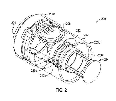
[0006] FIG. 2 is an isometric view of an exemplary float valve
assembly.
[0007] FIGS. 3A-3C are progressive cross-sectional side views of the
assembly of FIG. 2.
DETAILED DESCRIPTION
[0008] The present disclosure is related to downhole tools and, more
particularly, to a float valve assembly that relies on drag forces to
deactivate.
[0009] Embodiments described herein provide a float valve assembly
that relies on drag forces generated by a drag body connected to an activation
member. The drag body is positioned within a flow path of fluids flowing out
of
the float valve assembly in the downhole direction. Increasing the flow rate
of
the fluid in the downhole direction serves to correspondingly increase an
axial
force assumed by the activation member until the axial force is sufficient to
move the activation member out of engagement with a flapper pivotably
positioned in the float valve assembly. Moving the activation member out of
engagement with the flapper allows the flapper to move to a closed position,
where fluid flow in the uphole direction is prevented while fluid flow in the
downhole direction is allowed. Accordingly, the embodiments of the present
disclosure provide a tool that allows for surface circulation through the
float
2
CA 02995342 2018-02-09
WO 2017/052556
PCT/US2015/051988
valve assembly, but is not dependent on a wellbore projectile for
deactivation.
Moreover, the drag body allows for larger circulation flow paths and increased
deactivation accuracy. As a result, circulation can be carried out for an
extended
period of time without risking plugging or erosion of ball seat ports.
[0010] Referring to FIG. 1, illustrated is a cross-sectional side view of a
wellbore system 100 that may employ one or more of the principles of the
present disclosure. More particularly, FIG. 1 depicts a wellbore 102 that has
been drilled into the Earth's surface 104 and a surface casing 106 is extended
into the wellbore 102 from a wellhead installation 108 arranged at the surface
104. An inner string of casing 110 is also suspended within the wellbore 102
from the wellhead installation 108 and generally positioned within the surface
casing 106. A casing shoe 112 may be attached at the bottom-most portion of
the casing 110, and an annulus 114 is defined between the wellbore 102 and the
casing 110.
[0011] As used herein, the term "casing" refers to a plurality of tubular
pipe lengths coupled (e.g., threaded) together to form a continuous tubular
conduit of a desired length. It will be appreciated, however, that "casing"
may
alternatively refer to a single tubular pipe length or structure, without
departing
from the scope of the disclosure.
[0012] To secure the casing 110 within the wellbore 102, cement 116
may be pumped into the annulus 114. The cement 116 may be pumped into an
interior 118 of the casing 110 and flow to the bottom thereof where the casing
shoe 112 redirects the cement 116 back toward the surface 104 within the
annulus 114. At the surface 104, a feed line 120 may be operably and fluidly
coupled to the wellhead installation 108 and in fluid communication with the
interior 118 of the casing 110. The feed line 120 may be fluidly coupled to a
source 122 of the cement 116, and a feed valve 124 may regulate the flow of
the cement 116 into the interior 118 of the casing 110. In FIG. 1, the source
122 of the cement 116 is a cement truck, but could alternatively comprise a
cement head, a standalone pump, or any other cement pumping mechanism
capable of introducing the cement 116 into the casing 110. A return line 126
may also be connected to the wellhead installation 108 and in fluid
communication with the annulus 114. In some cases, as illustrated, the return
line 126 may include a return valve 128 configured to regulate the flow of
fluids
returning to the surface 104 via the annulus 114.
3
CA 02995342 2018-02-09
WO 2017/052556
PCT/US2015/051988
[0013] A float collar 132 may be included in the string of casing 110 at
or near the casing shoe 112, and a float valve assembly 134 may be positioned
within the float collar 132 and operable as auto-filling float equipment. More
particularly, the float valve assembly 134 may include a flapper (not shown)
that
is propped open while the casing 110 is advanced within the wellbore 102, and
thereby mitigating the hydraulic forces resulting from fluid interaction
between
the casing 110 and any wellbore fluids present within the wellbore 102. Prior
to
cementing the casing 110 in place, the flapper is allowed to move to its
closed
position where it can operate as a check valve that prevents fluid from
flowing
toward the surface 104 within the interior 118.
[0014] FIG. 2 is an isometric view of an exemplary float valve assembly
200, according to one or more embodiments of the present disclosure. The float
valve assembly 200 (hereafter the "assembly 200") may be the same as or
similar to the float valve assembly 134 of FIG. 1. Accordingly, the assembly
200
may be secured within the float collar 132 (FIG. 1) at a select location along
the
casing 110 (FIG. 1) and operate as auto-filling float equipment.
[0015] As illustrated, the assembly 200 may include a generally
cylindrical housing 202 having a first or uphole end 203a and a second or
downhole end 203b. A check valve 204 may be secured within the housing 202
at or near the uphole end 203a. While shown as two distinct components, the
check valve 204 and the housing 202 may, in at least one embodiment, form a
monolithic component of the assembly 200. In
some embodiments, as
illustrated, the check valve 204 may comprise a flapper-type check valve, but
could alternatively comprise other types of check valves including, but not
limited to a poppet valve, a ball valve, and a butterfly valve.
[0016] In the illustrated embodiment, the check valve 204 includes a
flapper 206 that is pivotably coupled to the check valve 204 and movable
between open and closed positions. When the flapper 206 is in the open
position, as depicted in FIG. 2, fluid flow through the assembly 200 between
the
uphole and downhole ends 203a,b (in either direction) is allowed. When the
flapper 206 is in the closed position, however, fluid flow through the
assembly
200 in the uphole direction (i.e., originating from the downhole end 203b) is
prevented, while fluid flow through the assembly 200 in the downhole direction
(i.e., originating from the uphole end 203a) is allowed.
4
CA 02995342 2018-02-09
WO 2017/052556
PCT/US2015/051988
[0017] The assembly 200 may further include an activation member
208 movably positioned within the housing 202. In some embodiments, as
illustrated, the activation member 208 may take the shape of a cylindrical
sleeve
or the like. The activation member 208 is movable between a first position,
where the activation member 208 engages and holds the flapper 206 in the open
position, and a second position, where the activation member 208 moves axially
within the housing 202 and out of engagement with the flapper 206. Once the
activation member 208 disengages the flapper 206, the flapper 206 will then be
able to pivot to the closed position.
[0018] A pair of lock rings may be used to help maintain the activation
member 208 in the first position. More particularly, a first or upper lock
ring
210a and a second or lower lock ring 210b may be positioned on opposing axial
ends of a radial shoulder 212 defined on the outer surface of the activation
member 208. One or both of the upper and lower lock rings 210a,b may
comprise a split lock ring that exhibits a known spring force. To move the
activation member 208 to the second position and out of engagement with the
flapper 206, the radial shoulder 212 must engage the lower lock ring 210b with
sufficient axial force to overcome its spring force.
Accordingly, the radial
shoulder 212 is secured axially between the upper and lower lock rings 210a,b
in
the first position until a required axial force is applied to the activation
member
208 in the downhole direction. This process will be described in more detail
below.
[0019] The assembly 200 may also include a drag body 214 coupled to
the activation member 208 and used to help the activation member 208 move
from the first position to the second position. In some embodiments, as
illustrated, the drag body 214 may form an integral extension of the
activation
member 208. In such embodiments, the, the drag body 214 and the activation
member 208 may form a monolithic structure. In other embodiments, however,
the drag body 214 may comprise one or more component parts or pieces that
may be operatively coupled to the activation member 208. In at least one
embodiment, as illustrated, the drag body 214 may extend axially from the
activation member 208 and at least partially out of the housing 202.
[0020] According to the present disclosure, and as will be described in
greater detail below, the drag body 214 may allow fluid flow circulation
through
the assembly 200 in both the uphole and downhole directions. Fluid flow in the
5
CA 02995342 2018-02-09
WO 2017/052556
PCT/US2015/051988
downhole direction, however, impinges on the drag body 214 and generates a
drag force that acts on the activation member 208 in the axial direction.
Increasing the downhole fluid flow through the assembly 200 may
correspondingly increase the drag force generated by the drag body 214. Once
a predetermined drag force is generated, the spring force of the lower lock
ring
210b may be overcome at the radial shoulder 212, thereby allowing the
activation member 208 to move to the second position and out of engagement
with the flapper 206.
[0021] FIGS. 3A-3C are progressive cross-sectional side views of the
assembly 200, according to one or more embodiments. More particularly, FIGS.
3A-3C depict the assembly 200 as the activation member 208 moves from the
first position, where the flapper 206 is in the open position as shown in
FIGS. 3A
and 3B, to the second position, where the flapper 206 is moved to the closed
position as shown in FIG. 3C. Similar numerals from FIG. 2 that are used in
FIGS. 3A-3C correspond to like elements or components of the assembly 200
that may not be described again.
[0022] As illustrated, the housing 202 may define an inner flow path
302 for fluids to communicate through the assembly 200 in either direction
(uphole or downhole) between the uphole and downhole ends 203a,b of the
housing 202. The check valve 204 may be secured within the housing 202, and
the flapper 206 and the activation member 208 may be arranged within the
inner flow path 302. The flapper 206 is pivotable about a pin 304, and is
biased
toward the closed position with a torsion spring 306 (FIG. 3C). As shown in
FIGS. 3A and 3B, when the activation member 208 is in the first position, the
flapper 206 may be propped in the open position by engaging and otherwise
resting on an uphole end 308a of the activation member 208. Once the
activation member 208 is moved to the second position and out of engagement
with the flapper 206, the spring force of the torsion spring 606 may urge the
flapper 206 to the closed position.
[0023] In the closed position, an angled surface 310 defined about the
periphery of the flapper 206 may be received by a correspondingly angled
flapper seat 312 defined on the check valve 204. In some embodiments, the
angled surface 310 may sealingly engage the angled flapper seat 312, and
thereby prevent fluid flow in the uphole direction (i.e., to the left in FIGS.
3A-
3C) through the assembly 200. Moreover, in some embodiments, a seal 314 be
6
CA 02995342 2018-02-09
WO 2017/052556
PCT/US2015/051988
provided about the circumference of the flapper 206 and may also sealingly
engage the angled flapper seat 312 when the flapper 206 is moved to the closed
position.
[0024] The radial shoulder 212 may form an annular ring that extends
about the entire outer circumference of the activation member 208. In some
embodiments, as illustrated, the radial shoulder 212 defined on the outer
surface of the activation member 208 may provide a planar upper face 316a and
an angled lower face 316b. More particularly, the upper face 316a may be
defined generally orthogonal to a longitudinal axis of the assembly 200 and
otherwise face axially toward the uphole end 203a of the housing 202 at any
point thereon. Alternatively, the upper face 316a can be frustoconical by
flaring
upwardly and radially outward. Other shapes of the upper face 316a are also
contemplated, such as concave and/or convex contoured surfaces.
[0025] The angled lower face 316b faces radially outward and
downwardly (i.e., toward the downhole end 203b of the housing 202) at any
point thereon. By further example, the lower face 316b can form an oblique
angle relative to the longitudinal axis of the assembly 200. Such an angle can
be selected to determine, at least in part, the axial force required to shift
the
radial shoulder 212 axially past the lower lock ring 210b. The angle defined
by
the lower face 316b, for example, can range between about 100 and about 80
with respect to the longitudinal axis of the assembly 200. Depending on the
given flow geometry for the assembly, however, the angle defined by the lower
face 316b can be adjusted to any angle between 0 and 90 to alter or
customize the axial force required to shift the radial shoulder 212 axially
past
the lower lock ring 210b. As will be appreciated, the greater the angle of the
angled lower face 316b, the greater the axial force required to shift the
radial
shoulder 212 axially past the lower lock ring 210b. On the other hand, smaller
angles can result in a smaller required axial force. The required force,
however,
is sufficient to avoid premature axial movement of the activation member 208
to
the second position.
[0026] The upper and lower lock rings 210a may be positioned within
upper and lower annular recesses 318a and 318b, respectively, defined in the
outer housing 202. One or both of the upper and lower lock rings 210a,b may
be formed as circumferentially discontinuous rings that can radially expand to
increase its circumference. The upper and lower lock rings 210a,b may be
7
CA 02995342 2018-02-09
WO 2017/052556
PCT/US2015/051988
formed of a variety of materials including, but not limited to, brass,
aluminum,
steel, spring steel, a composite material, an elastonner, a plastic, a
thermoplastic, a thermoset polymer, and any combination thereof. Material
selection for the upper and lower lock rings 210a,b can provide predetermined
retention of the radial shoulder 212 up to selected force limits, beyond which
the
upper and lower lock rings 210a,b may be elastically or plastically deformed
to
allow passage of the radial shoulder 212. Moreover, the materials for the
upper
and lower lock rings 210a,b may be selected to be easily drillable, since the
assembly 200 may eventually be drilled out after completion of a downhole
operation.
[0027] The upper lock ring 210a prevents the activation member 208
from moving upwardly (i.e., in the uphole direction) within the inner flow
path
302 by engaging the planar upper face 316a of the radial shoulder 212. As
shown in FIGS. 3A and 3B, the upper lock ring 210a may be biased to contract
radially inward such that the upper lock ring 210a contacts and engages the
upper face 316a of the radial shoulder 212. The upper face 316a and the
corresponding axial surface of the upper lock ring 210a may be such that an
upward force applied by the upper face 316a to the upper lock ring 210a does
not radially expand the upper lock ring 210a.
[0028] The lower lock ring 210b may be configured to engage the
angled lower face 316b of the radial shoulder 212 and may, in some
embodiments, define a correspondingly angled surface 320. More particularly,
the angled surface 320 of the lower lock ring 21b may be configured to axially
engage the angled lower face 316b of the radial shoulder 212. For example, the
angled surface 320 can form an oblique angle relative to the longitudinal axis
of
the assembly 200, and the angle of the angled surface 320 can determine, at
least in part, the force required to shift the activation member 208 past the
lower lock ring 210b. In some embodiments, the angle formed by the angled
surface 320 can be equal to the angle formed by the angled lower face 316b.
[0029] Other radial locking mechanisms can be used to controllably
retain the activation member 208 in the first position. For example, one or
more
retractable protrusions, biased radially inwardly, can individually engage
corresponding portions of the radial shoulder 212. By further example, a
radial
locking mechanism can be provided to retain the activation member 208 until a
force by the activation member 208 causes elastic or plastic deformation of
such
8
CA 02995342 2018-02-09
WO 2017/052556
PCT/US2015/051988
a radial locking mechanism.
Other locking methods could include collet
mechanisms, j-slots, snap-fit, interference fit, or friction alone.
[0030] The drag body 214 may be coupled to and extend from the
downhole end 308b of the activation member 208. In some embodiments, as
mentioned above, the drag body 214 forms an integral extension of the
activation member 208 such that the activation member 208 and the drag body
214 form a monolithic component or part of the assembly 200. In other
embodiments, however, the drag body 214 may comprise one or more
component parts that may be assembled and operatively coupled to the
activation member 208. As indicated above, the drag body 214 may be
configured to generate a drag force as fluid circulates through the assembly
200
in the downhole direction and impinges on the drag body 214. The resulting
drag force acts on the activation member 208 in the axial direction as an
axial
force, and increasing the axial force to a predetermined level allows the
radial
shoulder 212 to overcome the spring force of the lower lock ring 210b and move
the activation member 208 to the second position.
[0031] To generate sufficient drag force that translates into axial force
utilized by the activation member 208, the drag body 214 may exhibit several
designs or configurations. While one general design of the drag body 214 is
specifically shown and described herein, it will be appreciated that numerous
other designs and configurations of the drag body 214 may alternatively be
employed, without departing from the scope of the disclosure.
[0032] In the illustrated embodiment, the drag body 214 is depicted as
comprising a disc 322 operatively coupled to the activation member 208 by one
or more longitudinally extending ribs 324. The disc 322 may provide an uphole
or first face 326a and a downhole or second face 326b. The uphole face 326a
faces generally in the uphole direction (i.e., to the left in FIGS. 3A-3C),
and the
downhole face 326b is opposite the uphole face 326a and faces generally in the
downhole direction (i.e., to the right in FIGS. 3A03C). In some embodiments,
one or both of the uphole and downhole faces 326a,b may be positioned
orthogonal to the longitudinal axis of the assembly 200. In other embodiments,
one or both of the uphole and downhole faces 326a,b may be positioned at an
angle with respect to the longitudinal axis of the assembly 200, without
departing from the scope of the disclosure.
9
CA 02995342 2018-02-09
WO 2017/052556
PCT/US2015/051988
[0033] The disc 322 may be circular in shape, as illustrated, but could
alternatively exhibit any other cross-sectional shape including, but not
limited to,
oval, kidney-shaped, polygonal (e.g., triangular, square, rectangular, etc.),
teardrop-shaped, airfoil-shaped, or any combination thereof. In
some
embodiments, one or more holes 328 may be defined in the disc 322 and extend
between the uphole and downhole faces 326a,b. As will be appreciated, the
holes 328 may help modify or optimize the drag force generated by the drag
body 214 and, more particularly, by the disc 322. An increased number or size
of the holes 328, for example, will decrease the drag force generated by the
drag body 214. In contrast, a decreased number or size of the holes 328 will
increase the drag force generated by the drag body 214.
[0034] The ribs 324 may define one or more flow windows 330 through
which fluids may flow during operation of the assembly 200. As will be
appreciated, the number of flow windows 318 may depend on the number of ribs
324 extending between the disc 322 and the activation member 208. In some
embodiments, the ribs 324 may comprise rigid members, but could alternatively
be flexible, elastic, or limp members, depending on the materials used. For
instance, in some embodiments, one or both of the disc 322 and the ribs 324
may be made of a fabric material. In such embodiments, the drag body 214
may operate similar to a parachute in generating the drag force. Moreover, in
such embodiments, the cross-sectional shape of the disc 322 and/or the ribs
324
may vary.
[0035] The geometry of one or both of the disc 322 and the ribs 324
may be modified to alter and optimize the drag force generated by the drag
body 214 at a given flow rate through the assembly 200 in the downhole
direction, and thereby modify the axial force assumed by the activation member
208. More particularly, the shape and size of the disc 322 and/or the ribs 324
may be altered to provide a larger or smaller drag force relative to a known
flow
rate of fluid flowing through the inner flow path 302 in the downhole
direction.
A smaller-sized disc 322, for example, would result in a smaller drag force
being
generated as fluids impinge upon the uphole face 326a of the disc 322. A
larger-sized disc 322, however, would result in a larger drag force being
generated as the fluids impinge upon the uphole face 326a of the disc 322.
Moreover, as mentioned above, the size and number of the holes 328 defined
CA 02995342 2018-02-09
WO 2017/052556
PCT/US2015/051988
through the disc 322 may be altered to achieve an increased or decreased drag
force, as desired.
[0036] Similarly, larger (angularly thicker) ribs 324 may reduce the size
of the flow windows 330 and thereby increase the drag force generated as more
fluid is able to impinge on the ribs 324. On the other hand, smaller
(angularly
thinner) ribs 324 will increase the size of the flow windows 330 and thereby
decrease the drag force generated as less fluid will impinge on the ribs 324.
[0037] Moreover, in some embodiments, one or both of the disc 322
and the ribs 324 may be coated (covered) with various materials or coatings.
These materials and coatings may prove advantageous in changing the
coefficient of friction, thus allowing the drag force to be adjusted or
customized.
[0038] In embodiments where the drag body 214 comprises one or
more component parts or pieces coupled to the downhole end 308b of the
activation member 208, the drag body 214 may be considered modular. More
particularly, in such embodiments, parts of the drag body 214 may be switched
or substituted with parts of different sizes, configurations, or of different
materials in order to optimize operation of the drag body 214 for a particular
application. For example, in at least one embodiment, the disc 322 might be
swapped out at a rig site for a disc 322 of a different size or made of a
different
material such that it will be more amenable to the well where the assembly 200
will be deployed. Similarly, the ribs 324 might be swapped out at the rig site
for
ribs 324 of a different size or made of different materials to fit a
particular
downhole operation. Accordingly, the drag body 214 may be modular in fashion
so that different drag profiles may be generated depending on job specific
parameters. As will be appreciated, this allows for the drag force required to
deactivate the flapper 206 to be tailored for each operating situation.
[0039] Exemplary operation of the assembly 200 is now provided with
continued reference to FIGS. 3A-3C. Reference is first made to FIG. 3A. The
float collar 132 (FIG. 1) including the assembly 200 is run into the wellbore
102
(FIG. 1) as coupled to the inner casing 110 (FIG. 1). The wellbore 102 is
generally filled with fluid, such as drilling mud, and the casing 110 is
floated into
the wellbore 110. While the casing 110 is advanced within the wellbore 102,
the
flapper 206 is maintained in the open position by engaging the uphole end 308a
of the activation member 208. As a result, fluids may circulate through the
assembly 200 in the uphole direction, as indicated by the arrows in FIG. 3A.
As
11
CA 02995342 2018-02-09
WO 2017/052556
PCT/US2015/051988
illustrated, the fluid may flow around the drag body 214 to enter the inner
flow
path 302. More particularly, the fluid may flow through the flow windows 330
and, if included, through the holes 328 defined in the disc 322 to access the
inner flow path 302.
[0040] In FIG. 3B, once the assembly 200 is advanced to a
predetermined location within the wellbore 102 (FIG. 1), a fluid may be
circulated from the surface 104 (FIG. 1) and through the assembly 200 in the
downhole direction, as indicated by the arrows of FIG. 3B. In
some
embodiments, the fluid may be cement 116 (FIG. 1) used to fill the annulus 114
(FIG. 1), but may alternatively comprise a drilling fluid, water, or brine. As
long
as the flow rate of the fluid in the downhole direction is lower than the flow
rate
that results in deactivating the flapper 206, the activation member 208 will
stay
held in place by the upper and lower lock rings 210a,b.
[0041] To deactivate the float collar 132 (FIG. 1) and thereby move the
flapper 206 to the closed position, the activation member 208 must be moved to
the second position and otherwise out of engagement with the flapper 206 at
its
uphole end 308a. This may be accomplished by increasing the flow rate of the
fluid in the downhole direction, which correspondingly increases the drag
force
generated by the drag body 214. As the drag force increases, the axial force
assumed by the activation member 208 correspondingly increases and forces the
radial shoulder 212 against the lower lock ring 210b in the downhole
direction.
Once a predetermined axial force is applied against the lower lock ring 210b,
the
spring force of the lower lock ring 210b may be overcome, thereby allowing the
radial shoulder 212 to bypass the lower lock ring 210 and move the activation
member 208 axially to the second position.
[0042] In FIG. 3C, once the activation member 208 moves out of
engagement with the flapper 206, the hydrostatic pressure in the wellbore 102
(FIG. 1) and the spring force of the torsion spring 306 may urge the flapper
206
to the closed position 206. In the closed position, the angled surface 310 of
the
flapper 206 and the seal 314 may be received by the angled flapper seat 312
defined on the check valve 204. The sealing engagement between the flapper
seat 312 and the angle surface 310 and the seal 314 may prevent fluid flow in
the uphole direction (i.e., to the left in FIGS. 3A-3C) through the assembly
200.
[0043] With the activation member 208 in the second position, the
lower lock ring 210b may contract radially inward again and engage the upper
12
CA 02995342 2018-02-09
WO 2017/052556
PCT/US2015/051988
face 316a of the radial shoulder 212, thereby preventing the activation member
208 from moving axially uphole again. The surface contours of the lower lock
ring 210b and the planar upper face 316a can be such that an upward force
applied by the upper face 316a to the lower lock ring 210b does not tend to
cause radial expansion of the lower lock ring 210b. Moreover, the angled lower
face 316b of the radial shoulder 212 can settle upon and otherwise engage a
reduced diameter portion 332 of the housing 202. In some embodiments, the
lower face 316b and the reduced diameter portion 332 can provide
complementary surface contours to maximize an amount of surface contact
between the lower face 316b and the reduced diameter portion 332.
[0044] With the flapper 206 in the closed position, a cementing
operation can commence where the cement 116 (FIG. 1) is pumped through the
assembly 200 in the downhole direction. The fluid pressure of the cement 116
may overcome the spring force of the torsion spring 306 and the hydrostatic
pressure below the assembly 200, thereby allowing the flapper 206 to re-open
and otherwise allow the cement 116 to traverse the assembly 200 in the
downhole direction. The flapper 206, however, is able to control any back flow
of the cement 116 in the uphole direction, as the angled surface 310 of the
flapper 206 and the seal 314 sealingly engage the angled flapper seat 312
defined on the check valve 204.
[0045] After the cementing operation is completed, the assembly 200
may be drilled out by means known in the art to provide an open casing bore to
the bottom of the casing 110 (FIG. 1).
[0046] Still referring to FIGS. 3A-3C, in some embodiments, increasing
the drag force on the drag body 214 may be insufficient to move the activation
member 208 to the second position. Such a scenario may occur when the drag
body 214 is damaged or otherwise inoperable. In such embodiments, the
activation member 208 may further include an annular lip 334 extending from
an inner wall thereof. The annular lip 334 can have an inner cross-sectional
dimension (e.g., a diameter) that is smaller than an outer cross-sectional
dimension (e.g., a diameter) of a wellbore projectile, such as a ball, a plug,
or a
dart. Accordingly, when the drag body 214 is unable to generate sufficient
drag
force to move the activation member 208 to the second position, the wellbore
projectile may be sent downhole engage the annular lip 334. Upon landing on
and sealing against the annular lip 334, pressure within the inner flow path
302
13
CA 02995342 2018-02-09
WO 2017/052556
PCT/US2015/051988
may be increased to provide the axial force required to overcome the spring
force of the lower lock ring 210b and thereby bypass the lower lock ring 210b.
The annular lip 334 can be further configured to bend, expand, or bow radially
outwardly upon application of a predetermined fluid pressure so that the
wellbore projectile can be forced out the assembly 200 for cementing
operations.
[0047] Those skilled in the art will readily appreciate the several
advantages that the assembly 200 may provide. For instance, the assembly 200
allows required surface circulation, but is not dependent on a wellbore
projectile
to deactivate the flapper 206 (i.e., move the flapper 206 to the closed
position).
Moreover, as opposed to conventional activation members, incorporation of the
drag body 214 may facilitate larger circulation flow paths and increased
deactivation accuracy. Larger circulation flow paths through the drag body 214
will make the assembly 200 less susceptible to clogging and erosion, which
could
otherwise cause early deactivation of the flapper 206 or result in the need
for
unusually high deactivation flow rates. Accordingly, surface circulation
through
the assembly 200 can be carried out for extended periods of time, as long as
the
flow rate is below the flow rate that generates the drag force sufficient to
move
the activation member 208 to the second position without concern for erosion
of
flow ports or other critical components.
[0048] Embodiments disclosed herein include:
[0049] A. A float valve assembly that includes a cylindrical housing that
defines an inner flow path, a check valve positioned within the housing and
movable between an open position, where fluid flow through the inner flow path
in an uphole direction and a downhole direction is allowed, and a closed
position,
where fluid flow in the uphole direction is prevented while fluid flow in the
downhole direction is allowed, an activation member movably positioned within
the housing between a first position, where the activation member engages and
holds the check valve in the open position, and a second position, where the
activation member moves axially within the housing and out of engagement with
the check valve, and a drag body coupled to and extending from a downhole end
of the activation member, wherein fluid flow in the downhole direction
generates
a drag force on the drag body that places an axial force on the activation
member to move the activation member from the first position to the second
position.
14
CA 02995342 2018-02-09
WO 2017/052556
PCT/US2015/051988
[0050] B. A method of operating a float valve assembly that includes
flowing a fluid to a cylindrical housing that defines an inner flow path,
wherein a
check valve is positioned within the housing, holding the check valve in an
open
position with an activation member positioned within the housing in a first
position and flowing the fluid through the inner flow path in a downhole
direction, generating a drag force on a drag body with the fluid flowing in
the
downhole direction, wherein the drag body is coupled to and extends from a
downhole end of the activation member and the drag force thereby places an
axial force on the activation member, increasing a flow rate of the fluid in
the
downhole direction and thereby generating an increased drag force on the drag
body and an increased axial force on the activation member, moving the
activation member to a second position and out of engagement with the check
valve in response to the increased axial force, and moving the check valve to
a
closed position where fluid flow in an uphole direction within the inner flow
path
is prevented while fluid flow in the downhole direction is allowed.
[0051] C. A method that includes advancing a float valve assembly
coupled to a casing into a wellbore, the float valve assembly including a
cylindrical housing that defines an inner flow path, wherein a check valve is
positioned within the housing and held in an open position with an activation
member positioned within the housing in a first position flowing a fluid
through
the inner flow path in an uphole direction as the float valve assembly
advances
within the wellbore, circulating a fluid through the inner flow path in a
downhole
direction upon locating the casing at a desired location, generating a drag
force
on a drag body with the fluid flowing in the downhole direction, wherein the
drag
body is coupled to and extends from a downhole end of the activation member
and the drag force thereby places an axial force on the activation member,
increasing a flow rate of the fluid in the downhole direction and thereby
generating an increased drag force on the drag body and an increased axial
force on the activation member, moving the activation member to a second
position and out of engagement with the check valve in response to the
increased axial force, and moving the check valve to a closed position where
fluid flow in an uphole direction within the inner flow path is prevented
while
fluid flow in the downhole direction is allowed.
[0052] Each of embodiments A, B, and C may have one or more of the
following additional elements in any combination: Element 1: wherein the check
CA 02995342 2018-02-09
WO 2017/052556
PCT/US2015/051988
valve is a flapper-type check valve that includes a flapper pivotably coupled
to
the check valve, and wherein the activation member in the first position
engages
and holds the flapper in the open position and disengages the flapper upon
moving to the second position. Element 2: further comprising a radial shoulder
defined on an outer surface of the activation member, an upper lock ring
positioned on an uphole end of the radial shoulder, and a lower lock ring
positioned on a downhole end of the radial shoulder, wherein the axial force
on
the activation member forces the radial shoulder against the lower lock ring
to
bypass the lower lock ring. Element 3: wherein the lower lock ring comprises a
split lock ring that exhibits a known spring force and the axial force on the
activation member allows the radial shoulder to overcome the known spring
force. Element 4: wherein the drag body forms an integral extension of the
activation member such that the drag body and the activation member form a
monolithic structure. Element 5: wherein the drag body comprises a plurality
of
component parts operatively coupled to the activation member. Element 6:
wherein the drag body comprises one or more ribs coupled to the downhole end
of the activation member and extending axially therefrom, and a disc coupled
to
the one or more ribs, wherein the one or more ribs define one or more flow
windows through which the fluid flow traverses during operation. Element 7:
wherein the disc exhibits a cross-sectional shape selected from the group
consisting of circular, oval, kidney-shaped, polygonal, teardrop-shaped,
airfoil-
shaped and any combination thereof. Element 8: further comprising one or
more holes defined in the disc that extend between an uphole face and a
downhole face of the disc.
[0053] Element 9: wherein a radial shoulder is defined on an outer
surface of the activation member, the method further comprising maintaining
the activation member in the first position with an upper lock ring positioned
on
an uphole end of the radial shoulder and a lower lock ring on a downhole end
of
the radial shoulder. Element 10: wherein moving the activation member to the
second position comprises forcing the radial shoulder against the lower lock
ring
and bypassing the lower lock ring. Element 11: wherein the lower lock ring
comprises a split lock ring that exhibits a known spring force, the method
further
comprising overcoming the known spring force with the increased axial force.
Element 12: wherein the drag body includes one or more ribs coupled to the
downhole end of the activation member and extending axially therefrom, and a
16
CA 02995342 2018-02-09
WO 2017/052556
PCT/US2015/051988
disc coupled to the one or more ribs, and wherein generating the drag force on
the drag body comprises impinging the fluid on the one or more ribs and the
disc.
[0054] Element 13: further comprising pumping a cement through the
float valve assembly in the downhole direction, and preventing the cement from
back flowing through the float valve assembly in the uphole direction with the
check valve. Element 14: wherein a radial shoulder is defined on an outer
surface of the activation member, the method further comprising maintaining
the activation member in the first position with an upper lock ring positioned
on
an uphole end of the radial shoulder and a lower lock ring on a downhole end
of
the radial shoulder, and forcing the radial shoulder against the lower lock
ring
and thereby bypassing the lower lock ring to move the activation member to the
second position. Element 15: wherein the lower lock ring comprises a split
lock
ring that exhibits a known spring force, the method further comprising
overcoming the known spring force with the increased axial force. Element 16:
further comprising modifying a geometry of the drag body and thereby altering
the drag force generated by the drag body and the axial force assumed by the
activation member. Element 17: wherein the drag body includes one or more
ribs coupled to the downhole end of the activation member and extending
axially
therefrom, and a disc coupled to the one or more ribs, and wherein modifying
the geometry of the drag body comprises altering at least one of a shape and a
size of one or both of the disc and the one or more ribs. Element 18: wherein
the drag body includes one or more ribs coupled to the downhole end of the
activation member and extending axially therefrom, and a disc coupled to the
one or more ribs, and wherein modifying the geometry of the drag body
comprises switching out at least one of the disc and the one or more ribs with
a
corresponding disc or a corresponding one or more ribs that exhibit at least
one
of a different size, a different configuration, or made of a different
material.
[0055] By way of non-limiting example, exemplary combinations
applicable to A, B, and C include: Element 2 with Element 3; Element 6 with
Element 7; Element 6 with Element 8; Element 9 with Element 10; Element 10
with Element 11; Element 14 with Element 15; Element 16 with Element 17; and
Element 17 with Element 18.
[0056] Therefore, the disclosed systems and methods are well adapted
to attain the ends and advantages mentioned as well as those that are inherent
17
CA 02995342 2018-02-09
WO 2017/052556
PCT/US2015/051988
therein. The particular embodiments disclosed above are illustrative only, as
the
teachings of the present disclosure may be modified and practiced in different
but equivalent manners apparent to those skilled in the art having the benefit
of
the teachings herein. Furthermore, no limitations are intended to the details
of
construction or design herein shown, other than as described in the claims
below. It
is therefore evident that the particular illustrative embodiments
disclosed above may be altered, combined, or modified and all such variations
are considered within the scope of the present disclosure. The systems and
methods illustratively disclosed herein may suitably be practiced in the
absence
of any element that is not specifically disclosed herein and/or any optional
element disclosed herein. While compositions and methods are described in
terms of "comprising," "containing," or "including" various components or
steps,
the compositions and methods can also "consist essentially of" or "consist of"
the
various components and steps. All numbers and ranges disclosed above may
vary by some amount. Whenever a numerical range with a lower limit and an
upper limit is disclosed, any number and any included range falling within the
range is specifically disclosed. In particular, every range of values (of the
form,
"from about a to about b," or, equivalently, "from approximately a to b," or,
equivalently, "from approximately a-b") disclosed herein is to be understood
to
set forth every number and range encompassed within the broader range of
values. Also, the terms in the claims have their plain, ordinary meaning
unless
otherwise explicitly and clearly defined by the patentee. Moreover, the
indefinite
articles "a" or "an," as used in the claims, are defined herein to mean one or
more than one of the elements that it introduces. If there is any conflict in
the
usages of a word or term in this specification and one or more patent or other
documents that may be incorporated herein by reference, the definitions that
are
consistent with this specification should be adopted.
[0057] As used herein, the phrase "at least one of" preceding a series of
items, with the terms "and" or "or" to separate any of the items, modifies the
list
as a whole, rather than each member of the list (i.e., each item). The phrase
"at least one of" allows a meaning that includes at least one of any one of
the
items, and/or at least one of any combination of the items, and/or at least
one
of each of the items. By way of example, the phrases "at least one of A, B,
and
C" or "at least one of A, B, or C" each refer to only A, only B, or only C;
any
combination of A, B, and C; and/or at least one of each of A, B, and C.
18
CA 02995342 2018-02-09
WO 2017/052556
PCT/US2015/051988
[0058] The use of directional terms such as above, below, upper, lower,
upward, downward, left, right, uphole, downhole and the like are used in
relation
to the illustrative embodiments as they are depicted in the figures, the
upward
direction being toward the top of the corresponding figure and the downward
direction being toward the bottom of the corresponding figure, the uphole
direction being toward the surface of the well and the downhole direction
being
toward the toe of the well.
19