Language selection

Search

Patent 2995792 Summary

Third-party information liability

Some of the information on this Web page has been provided by external sources. The Government of Canada is not responsible for the accuracy, reliability or currency of the information supplied by external sources. Users wishing to rely upon this information should consult directly with the source of the information. Content provided by external sources is not subject to official languages, privacy and accessibility requirements.

Claims and Abstract availability

Any discrepancies in the text and image of the Claims and Abstract are due to differing posting times. Text of the Claims and Abstract are posted:

  • At the time the application is open to public inspection;
  • At the time of issue of the patent (grant).
(12) Patent: (11) CA 2995792
(54) English Title: RAILWAY CAR TRUCK FRICTION SHOE
(54) French Title: SABOT DE FRICTION DESTINE A UN WAGON
Status: Granted
Bibliographic Data
(51) International Patent Classification (IPC):
  • B61F 5/12 (2006.01)
  • B61F 5/06 (2006.01)
(72) Inventors :
  • COSEGLIA, JOHN (United States of America)
(73) Owners :
  • AMSTED RAIL COMPANY, INC. (United States of America)
(71) Applicants :
  • AMSTED RAIL COMPANY, INC. (United States of America)
(74) Agent: GOWLING WLG (CANADA) LLP
(74) Associate agent:
(45) Issued: 2020-03-24
(22) Filed Date: 2018-02-21
(41) Open to Public Inspection: 2018-09-08
Examination requested: 2018-02-21
Availability of licence: N/A
(25) Language of filing: English

Patent Cooperation Treaty (PCT): No

(30) Application Priority Data:
Application No. Country/Territory Date
15/453,515 United States of America 2017-03-08

Abstracts

English Abstract

A friction shoe for a railway car truck is provided. The railway truck comprises two parallel side frames, a suspension spring assembly supported by the side frames, and a bolster transversely mounted between the side frames and supported by the suspension spring assembly. Each side frame has at least one vertical support face,and the bolster has at least one sloped support face. The friction shoe comprises a bottom base engaging and supported by a pair of support springs, and a sloped wall engaging the sloped support face of the bolster. The bottom base includes a cylindrical spring lug that has a center opening that extends through the spring lug. The bottom surface of the spring lug is flat and smooth and is designed to engage with and provides the ability to use an additional concentrically nested support spring. The additional spring increases the force between the vertical support face of the wedge and the vertical wear plate of the side frame.


French Abstract

Linvention concerne un sabot de friction pour wagon. Le wagon comprend de cadres latéraux parallèles, un bloc-ressorts de suspension soutenu par les cadres latéraux et une traverse installée perpendiculairement entre les cadres latéraux et soutenue par le bloc-ressorts de suspension. Chaque cadre latéral dispose dau moins une paroi de support verticale, et la traverse présente au moins une paroi de support en pente. Le sabot de friction comprend une base montée connectée à une paire de ressorts de suspension, qui la supportent, et une paroi en pente qui se joint à la paroi de support en pente de la traverse. La base comprend un téton de ressort cylindrique comprenant une ouverture centrale qui le traverse. La surface inférieure du téton de ressort est plate et lisse, et conçue pour se joindre à un ressort de support supplémentaire concentrique et lutiliser. Le ressort supplémentaire augmente la force entre la paroi de support verticale du coin et la plaque dusure verticale du cadre latéral.

Claims

Note: Claims are shown in the official language in which they were submitted.

What is claimed is:
1. A railway car truck comprising
two parallel side frames, each side frame having at least one vertical support
face:
a suspension spring assembly supported by the side frames;
a bolster transversely mounted between the side frames and supported by the
suspension spring
assembly,
the bolster having at least one sloped support face; and
a friction shoe comprising:
two laterally spaced sloped walls each engaging one sloped support face of the
bolster;
a vertical wall engaging the vertical support face of the side frame;
a bottom base engaging and supported by a plurality of support springs,
the bottom base including a cylindrical spring lug extending downwardly
therefrom, the
cylindrical spring lug having a center opening leading into a hollow area of
the friction shoe and
having a smooth fiat bottom surface which engages with an inner one of the
support springs.
2. The friction shoe of claim 1, wherein
the friction shoe has two generally triangular side walls each having a
manufacturing core
support hole.
3. The friction shoe of claim 1, wherein
the friction shoe provides a normal force of between 2000 and 12,000 pounds.
6

4. The friction shoe of claim 1, wherein
the friction shoe provides a damping force of between 7500 and 12,000 pounds
when the friction
shoe is moving at a velocity of between 0 and 19 inches per second.
5. The friction shoe of claim 1, wherein
the friction shoe is comprised of cast iron.
6. The friction shoe of claim 1, wherein
the friction shoe is comprised of cast steel.
7. The friction shoe of claim 1, wherein
the friction shoe has a composite facing applied to the vertical support
surface.
8. The friction shoe of claim 1, wherein
the laterally spaced sloped walls are comprised of two laterally spaced
surfaces with a spacing
wall located between the two laterally spaced surfaces.
9. A friction shoe for a railway car truck, the friction shoe comprising:
a bottom base configured to engage and be supported by a support spring,
the bottom base including a generally cylindrical spring lug extending
downwardly therefrom;
a sloped wall configured to engage a sloped support face of a bolster;
and a vertical wall configured to engage a vertical support face of a side
frame.
7

10. The friction shoe of claim 9, wherein
the spring lug includes a hollow opening extending vertically through the
spring lug.
11. The friction shoe of claim 9, wherein
the friction shoe provides a damping force of between 7500 and 16,250 pounds
when the friction
shoe is moving at a velocity of between 0 and 19 inches per second.
12. The friction shoe of claim 9, wherein
the friction shoe provides a normal force of between 2000 and 12,000 pounds.
13. The friction shoe of claim 9, wherein
the friction shoe is comprised of cast iron.
14. The friction liner of claim 9, wherein
the friction shoe is comprised of cast steel.
15. The friction shoe of claim 9, wherein
the sloped wall extends to direct contact with the bottom base.
16. The friction shoe of claim 9 wherein
the sloped wall is comprised of two laterally spaced surfaces with a spacing
wall located between
the two laterally spaced surfaces.
8

17. A friction shoe for a railway car truck, the friction shoe comprising:
a bottom base configured to engage first and second concentrically nested
springs, the bottom
base including a spring lug extending downwardly therefrom, the spring lug
comprising:
a hollow opening extending vertically through the spring lug; and
a flat bottom surface, wherein the flat bottom surface provides a support
surface for a third
concentrically nested spring.
18. The friction shoe of claim 17, wherein the spring lug is cylindrical.
19. The friction shoe of claim 17, further comprising a sloped wall configured
to engage a sloped
support face of a bolster, the sloped wall extending to direct contact with
the bottom base.
20. The friction shoe of claim 18, further comprising a vertical wall
configured to engage a
vertical support face of a side frame.

9

Description

Note: Descriptions are shown in the official language in which they were submitted.


= F18324366CA
RAILWAY CAR TRUCK FRICTION SHOE
BACKGROUND AND SUMMARY OF THE INVENTION
The invention relates generally to railway car truck friction damping
arrangements, and
more particularly to a railway car truck friction shoe.
The present invention is directed to a friction wedge or shoe for a railroad
car truck and
in particular to a friction shoe including a body having a sloped face and a
vertical face. The
friction shoe dissipates energy throughout the range of suspension travel and
friction shoe and
bolster velocities moving vertically along the side frame column wear plate.
Railroad car trucks of a design known as a three piece railway car truck
include a pair of
spaced apart side frames and a bolster that extends transversely between the
side frames. The
bolster is resiliently supported at each end on a respective side frame by a
plurality of suspension
springs. Wedge shaped friction shoes are used in such railroad car trucks to
dampen movement
of the bolster with respect to the side frame of the railroad car truck.
Friction shoes are usually
generally triangular wedge shaped such that two laterally spaced sloped faces
are each in contact
with laterally spaced sloped faces of the bolster. The friction shoe is also
comprised of a vertical
face that is in contact with a corresponding wear plate mounted on a vertical
face of a side frame
column. Accordingly, the friction shoe acts as a motion damping wedge between
the bolster and
the wear plate on a vertical column of the side frame.
The friction shoe also is comprised of a bottom section that joins the
vertical face and the two
laterally sloped faces.
The wear plate on the vertical column of the side frame is usually comprised
of steel. The
friction shoe is typically wedged into engagement between the sloped faces of
the bolster and the
vertical column of the side frame by a pair of concentrically arranged
suspension springs. The
1
N177i73,
CA 2995792 2018-02-21

= H8324366CA
bottom section of the friction shoe includes a protrusion which serves to
constrain and locate the
suspension springs. Resistance to sliding movement of the friction shoe with
respect to the side
frame, which in turn provides dampening of vertical bolster movement, is
provided by the
frictional forces generated between the friction shoe vertical face and a wear
plate on the side
frame vertical column.
It is an object of the present invention to provide an improved railway car
truck friction
shoe that allows the use of an additional concentrically nested spring to
increase the damping
frictional force on the vertical movement of the bolster for better control
with greater energy
dissipation. The bottom section includes a spring lug in the form of a hollow
protrusion
extending from the bottom section. This spring lug not only constrains and
locates an outer and
middle pair of suspension springs, but also the bottom surface of the lug is
flat and smooth and is
designed to engage a third concentrically arranged inner suspension spring.
Additionally, the
spring lug is hollow and as a result facilitates manufacturing of the friction
shoe as the central
hole helps locate the sand core that forms the hollow interior of the friction
shoe. Further, the
bottom center of the spring lug is open which allows water or other debris to
pass through the
friction shoe instead of collecting inside it.
BRIEF DESCRIPTION OF THE DRAWING FIGURES
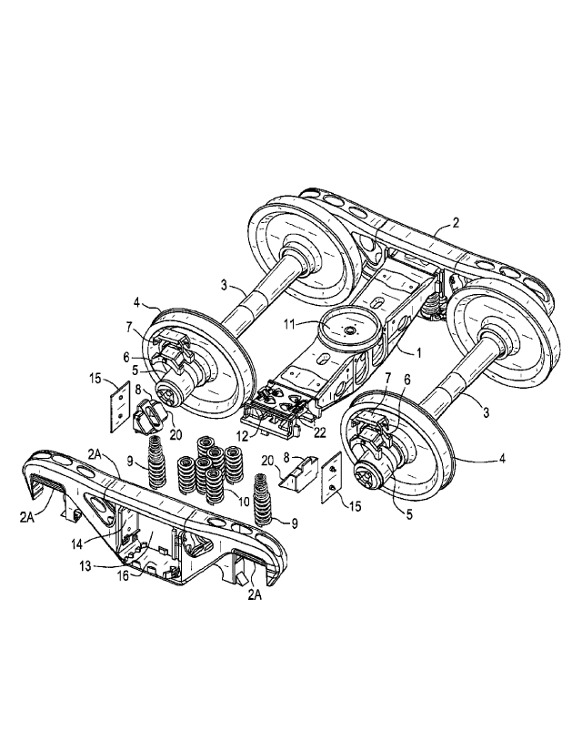
FIG. 1 is an exploded isometric view of a railway car truck in accordance with
an
embodiment of the present invention;
FIG. 2 is a detailed partial section view of a portion of a railway car truck
in accordance
with an embodiment of the present invention;
FIG. 3 is an isometric view of a friction shoe in accordance with an
embodiment of the
present invention;
2
#,77,
CA 2995792 2018-02-21

= 148324366CA
FIG. 4 is a bottom view of a friction shoe in accordance with an embodiment of
the
present invention, and
FIG. 5 is a side view of a friction shoe in accordance with an embodiment of
the present
invention.
DETAILED DESCRIPTION OF THE PREFERRED EMBODIMENT
Referring now to Fig. 1, a friction wedge or shoe 8 of the present invention
is shown in a
railroad car truck. The railway car truck includes two side frames 2 which are
spaced apart and
generally parallel to one another. Each side frame 2 includes a bolster
opening 13 formed by a
pair of spaced apart vertical columns 14. A planar wear plate 15 is connected
to the interior
surface of each column 14. The railway car truck also includes a bolster 1
which extends
generally transversely between the side frames 2. Each end 12 of the bolster 1
is located within a
respective bolster opening 13 and is vertically supported on a side frame 2 by
a plurality of
helical coil suspension springs 10. The bolster end 12 is also supported by
the friction shoes 8
which themselves are supported by suspension control springs 9. The suspension
control springs
9 and suspension springs 10 are themselves supported on a spring support
section 16 of each side
frame 2. Suspension control springs 9 and suspension springs 10 are
resiliently compressible to
thereby allow the ends of the bolster 1 to move vertically upwardly and
downwardly within the
bolster openings 13 and with respect to the side frames 2. Each bolster end 12
includes a
plurality of sloped walls 22. Each sloped wall 22 is adapted to engage a
sloped surface 20 of a
respective friction shoe 8. Friction shoe 8 is seen to provide a damping force
to the vertical
motion of bolster 1 while supported on suspension control springs 9 and
suspension springs 10 as
the railway car travels on the rails.
3
#177571i
CA 2995792 2018-02-21

H8324366CA
= =
Railway wheels 4 are mounted on axles 3. Axle bearings 5 are mounted on the
ends of
axles 3. Bearings adaptor 6 and pad 7 are provided to receive axle bearings in
side frame pedestal
openings 13. Center bowl 11 on the top surface of bolster 1 is provided to
help support the
railway freight car on the truck.
As best shown in Fig. 2, friction shoe 8 includes a body 17. Body 17 is
generally
triangular or wedge-shaped. The body 17 includes a base having a generally
horizontal bottom
wall 34. The bottom base surface 34 is adapted to engage the top end of a pair
of concentrically
nested suspension control springs 9 and includes a boss or spring lug 29 to
control the location of
the suspension control springs 9. Spring lug 29 is cylindrical in shape, the
bottom surface 41 of
spring lug 29 is flat and may have a center opening 39. The bottom surface 41
acts as a support
surface for a third concentrically nested inner suspension control spring 42
and as such, the
outside diameter is approximately the same size as the outside diameter of the
inner suspension
control spring and the inside diameter is approximately the same size as the
inside diameter of
the inner suspension control spring. Friction shoe body 17 is usually
comprised of cast iron or
cast steel.
As best shown in Figs. 3, 4, and 5, friction shoe body 17 also includes a
generally vertical
front wall 19. The body 17 also includes laterally spaced sloped walls 20 and
20A that extend at
an inclined angle of approximately thirty-five to forty-five degrees between
the base 34 and front
face 19. Sloped walls 20 and 20A are each adapted to engage an inclined walls
22 of the bolster
1. The front face 19 of friction shoe body 17 has an extension 31 that
protrudes approximately
one inch below the bottom base surface 34. Front face 19 of friction shoe body
17 is in direct
contact with and extends from an intersection with top edge 25 of sloped
surface 20 and 20A and
center spacing section 21. Center spacing section 21 extends between laterally
spaced sloped
4
41775715
CA 2995792 2018-02-21

= H8324366CA
walls 20 and 20A. Center spacing section 21 may include an opening 23 that
extends from near
the top edge 25 of friction shoe body 17 to near intersection 27 between
bottom base surface 34
and center spacing section 21. Center spacing section 21 may be recessed from
sloped surfaces
20 and 20A.
The damping force developed by the friction shoe 8 is proportional to the
force with
which the front face 19 is impinged against side frame column wear plate 15
and can be
increased by adding the third friction shoe supporting suspension control
spring 42. The design
of this friction shoe allows the inner suspension control spring 42 to be
utilized and can add 200
to 1500 pounds force per inch of compression to the vertical force under the
friction shoe.
5
#177,5
CA 2995792 2018-02-21

Representative Drawing
A single figure which represents the drawing illustrating the invention.
Administrative Status

For a clearer understanding of the status of the application/patent presented on this page, the site Disclaimer , as well as the definitions for Patent , Administrative Status , Maintenance Fee  and Payment History  should be consulted.

Administrative Status

Title Date
Forecasted Issue Date 2020-03-24
(22) Filed 2018-02-21
Examination Requested 2018-02-21
(41) Open to Public Inspection 2018-09-08
(45) Issued 2020-03-24

Abandonment History

There is no abandonment history.

Maintenance Fee

Last Payment of $277.00 was received on 2024-01-23


 Upcoming maintenance fee amounts

Description Date Amount
Next Payment if standard fee 2025-02-21 $277.00
Next Payment if small entity fee 2025-02-21 $100.00

Note : If the full payment has not been received on or before the date indicated, a further fee may be required which may be one of the following

  • the reinstatement fee;
  • the late payment fee; or
  • additional fee to reverse deemed expiry.

Patent fees are adjusted on the 1st of January every year. The amounts above are the current amounts if received by December 31 of the current year.
Please refer to the CIPO Patent Fees web page to see all current fee amounts.

Payment History

Fee Type Anniversary Year Due Date Amount Paid Paid Date
Request for Examination $800.00 2018-02-21
Registration of a document - section 124 $100.00 2018-02-21
Application Fee $400.00 2018-02-21
Final Fee 2020-04-01 $300.00 2020-01-15
Maintenance Fee - Application - New Act 2 2020-02-21 $100.00 2020-01-22
Maintenance Fee - Patent - New Act 3 2021-02-22 $100.00 2021-01-21
Maintenance Fee - Patent - New Act 4 2022-02-21 $100.00 2022-01-19
Maintenance Fee - Patent - New Act 5 2023-02-21 $210.51 2023-01-23
Maintenance Fee - Patent - New Act 6 2024-02-21 $277.00 2024-01-23
Owners on Record

Note: Records showing the ownership history in alphabetical order.

Current Owners on Record
AMSTED RAIL COMPANY, INC.
Past Owners on Record
None
Past Owners that do not appear in the "Owners on Record" listing will appear in other documentation within the application.
Documents

To view selected files, please enter reCAPTCHA code :


To view images, click a link in the Document Description column. To download the documents, select one or more checkboxes in the first column and then click the "Download Selected in PDF format (Zip Archive)" or the "Download Selected as Single PDF" button.

List of published and non-published patent-specific documents on the CPD .

If you have any difficulty accessing content, you can call the Client Service Centre at 1-866-997-1936 or send them an e-mail at CIPO Client Service Centre.


Document
Description 
Date
(yyyy-mm-dd) 
Number of pages   Size of Image (KB) 
Final Fee 2020-01-15 1 33
Cover Page 2020-02-24 1 55
Representative Drawing 2020-03-20 1 48
Cover Page 2020-03-20 1 55
Representative Drawing 2018-08-02 1 25
Representative Drawing 2020-02-24 1 24
Abstract 2018-02-21 1 24
Description 2018-02-21 5 194
Claims 2018-02-21 5 125
Drawings 2018-02-21 4 89
Amendment 2018-05-04 1 38
Representative Drawing 2018-08-02 1 25
Cover Page 2018-08-02 1 57
Examiner Requisition 2018-12-21 3 190
Amendment 2019-02-28 1 40
Examiner Requisition 2019-04-12 5 243
Amendment 2019-08-01 12 350
Claims 2019-08-01 4 96