Note: Descriptions are shown in the official language in which they were submitted.
CA 02995845 2018-02-15
WO 2017/034981 PCT/US2016/047777
LIQUID BIOMASS HEATING SYSTEM
CROSS REFERENCE TO RELATED APPLICATIONS
[0001] This application claims the benefit of priority from both U.S.
Provisional Patent
Application No. 62/208,351, filed on August 21, 2015, and U.S. Provisional
Patent Application
No. 62/220,785 filed on September 18, 2015. All of the foregoing related
applications, in their
entirety, are incorporated herein by reference.
FIELD OF THE INVENTION
[0002] The present disclosure generally relates to the introduction of a
renewable fuel or
renewable oil as a heating oil or fossil fuel substitute for use in boilers or
thermal applications.
More specifically, the present disclosure is directed to systems, methods, and
apparatuses utilizing
a liquid thermally produced from biomass into commercial and industrial boiler
or thermal
systems such as boilers, furnaces, and kilns, and methods for generating
renewable identification
numbers (RINs), alternative energy credits (AECs) and renewable energy credits
(RECs). An
aspect of this application and the various inventive embodiments herein are
systems, methods,
and fuels that are compliant with one or more of the various thermal energy
credit programs
enabling the combustion of unenriched renewable fuel oil, derived from
biomass, to additionally
earn thermal energy credits, for example, C-RNs, RNs, ACPs. RECs as well as
others.
BACKGROUND
[0003] Biomass has been a primary source of energy over much of human
history. During
the late 1800's and 1900's the proportion of the world's energy sourced from
biomass dropped, as
the commercial development and utilization of fossil fuels occurred, and
markets for coal and
petroleum products dominated. Nevertheless, some 15% of the world's energy
continues to be
sourced from biomass, and in developing countries the contribution of biomass
is much higher at
38%. In addition, there has been a new awareness of the impact of the
utilization of fossil fuels
on the environment. In particular, the contribution of greenhouse gases, as a
result of consuming
fossil fuels.
[0004] Biomass, such as wood, wood residues, and agricultural residues, can
be converted to
useful products, e.g., fuels or chemicals, by thermal or catalytic conversion.
An example of
thermal conversion is pyrolysis where the biomass is converted to a liquid and
char, along with a
gaseous co-product by the action of heat in essentially the absence of oxygen.
[0005] In a generic sense, pyrolysis is the conversion of biomass to a
liquid and/or char by
the action of heat, typically without involving any significant level of
direct combustion of the
biomass feedstock in the primary conversion unit.
1
CA 02995845 2018-02-15
WO 2017/034981 PCT/US2016/047777
[0006] Historically, pyrolysis was a relatively slow process where the
resulting liquid
product was a viscous tar and "pyroligneous" liquor. Conventional slow
pyrolysis has typically
taken place at temperatures below 400 C, and over long processing times
ranging from several
seconds to minutes or even hours with the primary intent to produce mainly
charcoal and
producing liquids and gases as by-products.
[0007] A more modern form of pyrolysis, or rapid thermal conversion, was
discovered in the
late 1970's when researchers noted that an extremely high yield of alight,
pourable liquid was
possible from biomass. In fact, liquid yields approaching 80% of the weight of
the input of a
woody biomass material were possible if conversion was allowed to take place
over a very short
time period, typically less than 5 seconds.
[0008] The homogeneous liquid product from this rapid pyrolysis, which has
the appearance
of a light to medium petroleum fuel oil, is a renewable fuel oil. In
particular, the renewable fuel
oil may be an unenriched renewable fuel oil, formed from a biomass comprising
cellulosic
material, wherein the only processing of the biomass may be a therma-
mechanical process
(specifically comprising grinding and rapid thermal processing, with no post
or further catalytic
processing, hydrogenation, or enrichment or other chemical upgrading of the
liquid prior to its use
as a combustion or renewable fuel).
[0009] In practice, the short residence time pyrolysis of biomass causes
the major part of its
organic material to be instantaneously transformed into a vapor phase. This
vapor phase contains
both non-condensable gases (including methane, hydrogen, carbon monoxide,
carbon dioxide and
olefins) and condensable vapors. It is the condensable vapors that constitute
the final liquid
product, when condensed and recovered, and the yield and value of this liquid
is a strong function
of the method and efficiency of the downstream capture and recovery system.
[0010] Given the fact that there is a limited availability of hydrocarbon
crude and an ever
increasing demand for energy, particularly liquid transportation fuels,
alternative sources are
therefore required. The abundance and sustainability of biomass makes
renewable feedstock an
attractive option to supplement the future demand for petroleum. The
difficulty with biomass is
the fact that it contains oxygen, unlike conventional hydrocarbon fuels, and
historically has not
been readily convertible into a form that can be easily integrated into
existing hydrocarbon based
infrastructure. In particular, utilization of unenriched pyrolysis oil as a
heating oil or fossil fuel
substitute has been limited due to its lower energy density, lower combustion
temperature,
relative thermal instability, corrosiveness, and limited miscibility with
traditional heating oil or
fossil fuels.
[0011] The lower energy density, lower combustion temperature, and poor
thermal stability
of unenriched pyrolysis oil are attributable in part to high water content
(typically > 20 wt.%) and
the presence of oxygenated hydrocarbons (typically > 40 wt.%). The oxygenated
compounds,
2
CA 02995845 2018-02-15
WO 2017/034981 PCT/US2016/047777
including carboxylic acids, phenols, cresols, and aldehydes, tend to undergo
secondary reactions
during storage, resulting in increased viscosity, phase separation and/or
solids formation.
Additionally, pyrolysis oil contains char and alkali metal contaminants which
appear to catalyze
these secondary reactions, further contributing to the stability problems.
[0012] As a result of the stability problems, storage of pyrolysis oil for
use as a heating oil or
fossil fuel substitute in combustion systems can be problematic. In
particular, viscosity changes
can occur at ambient storage temperature and may accelerate at higher
temperatures. Moreover,
rapid temperature changes can lead to phase separation of the pyrolysis oil
into an aqueous-rich
phase and an aqueous deficient phase. These changes may render the pyrolysis
oil unsuitable for
handling in conventional or existing fossil fuel-based infrastructure and
equipment, including
pumps, vessels, and boiler systems.
[0013] The corrosiveness and limited miscibility of pyrolysis oil are due
largely to its acidity
and its high moisture and oxygen contents. Pyrolysis oil typically has a pH <
3 and a TAN > 150,
making it corrosive to storage, pipes, existing fossil fuel-based
infrastructure and equipment,
including pumps, vessels, and boiler systems. In addition, the presence of
char and alkali metals
contribute to ash formation during combustion of pyrolysis oil. As a result,
unenriched pyrolysis
oil is not immediately compatible with existing liquid and/or fossil fuel-
based infrastructure as a
heating oil or fossil fuel substitute.
[0014] Upgrading pyrolysis oil to overcome the foregoing difficulties has
proven to be a
difficult challenge. The use of catalytic cracking of a solid or liquid
biomass, a biomass-derived
vapor, or a thermally-produced liquid as a means to produce hydrocarbons from
oxygenated
biomass is technically complex, relatively inefficient, and produces
significant amounts of low
value byproducts. To solve the catalyst and yield issues, researchers looked
at stand-alone
upgrading pathways where biomass-derived liquids could be converted to liquid
hydrocarbons
using hydrogen addition and catalyst systems in conversion systems that were
tailored specifically
for the processing of oxygenated materials (Elliott, Historical Developments
in Hydroprocessing
Bio-oils, Energy & Fuels 2007, 21, 1792-1815). Although technically feasible,
the large
economies-of-scale and the technical complexities and costs associated with
high-pressure multi-
stage hydrogen addition (required for complete conversion to liquid
hydrocarbon fuels) are
severely limiting and generally viewed as unacceptable. Other approaches such
as liquid-liquid
extraction, or gasification face similar hurdles, significantly reducing the
economic
competitiveness of pyrolysis oil as a petroleum substitute.
[0015] New approaches are needed to circumvent the foregoing limitations.
One innovative
embodiment that forms part of the present application is a method of
maintaining and handling an
unenriched renewable fuel oil for use as a heating oil or fossil fuel
substitute in a thermal system.
Applicable thermal systems include a boiler, a furnace, a kiln, and an
evaporative cooling system.
3
CA 02995845 2018-02-15
WO 2017/034981 PCT/US2016/047777
BRIEF SUMMARY OF THE INVENTION
[0016] Another innovative embodiment that forms part of the present
application is a boiler
comprising a dual-purpose or dual-fuel burner system with a post-combustion
purge system
capable of utilizing an unenriched renewable fuel oil. In an embodiment, the
dual-purpose or
dual-fuel burner is controllable to allow combustion or firing of either
heating oil no. 4, a fossil
fuel, or an unenriched renewable fuel oil at the appropriate fuel-to-air
ratios and volumetric flow
rates. The post-combustion purge system removes uncombusted unenriched
renewable fuel oil
from the vicinity of the burner, eliminating the presence of fuel when the
burner is shut down. As
set forth in the present disclosure, unexpected technical and economic
benefits may be gained in
the use of unenriched renewable fuel oil as a heating oil or fossil fuel
substitute in commercial and
industrial boilers.
[0017] In certain embodiments, the invention relates to a method of
combustion, comprising
burning two different fuels (for example, a heating fuel oil and an unenriched
renewable fuel oil)
in a burner. In certain embodiments, the burner may be an element of a boiler,
a furnace, a kiln,
or an evaporative cooling system. In certain embodiments, the invention
relates to a method of
combustion, comprising burning a first fuel in a burner at a temperature of
1,900 C to 2,300 C
with an atomized fuel-to-air ratio of 0.8:1 to 5:1 and burning a second fuel
in the burner at a
temperature of 1,300 C to 1,800 C with an atomized fuel to air ratio of
0.4:1 to 4:1. In certain
embodiments, the invention relates to a method of combustion, comprising
burning a first fuel
having an adiabatic flame temperature of 1,900 C to 2,300 C in a burner with
an fuel-to-air ratio
of 0.8:1 to 5:1 and burning a second fuel having an adiabatic flame
temperature of 1,300 C to
1,800 C in the burner with an fuel to air ratio of 0.4:1 to 4:1. In certain
embodiments, the
invention relates to a method of combustion, comprising burning a first fuel
in a burner with an
adiabatic flame temperature of 1,900 to 2,300 C and a fuel-to-air ratio
resulting in 1%, 2%, 3%,
4%, or between 2% and 4% oxygen in the combustion flue gas, and burning a
second fuel in the
burner with an adiabatic flame temperature at least 300 C below that of the
first fuel and an fuel-
to-air ratio resulting in 1%, 2%, 3%, 4%, or between 2% and 4% oxygen in the
combustion flue
gas produced by combustion of the second fuel.
[0018] In certain embodiments, the invention relates to a method of
combustion comprising
burning two different fuels, wherein the first fuel is a petroleum-based
heating fuel oil (for
example a no. 2, no. 4, no. 6 or waste oil) and the second fuel is an
unenriched renewable fuel oil.
In certain embodiments, the invention relates to a method of combustion
comprising burning two
different fuels, wherein the volume ratio of the first fuel and the second
fuel is in the range of
1:1.5 to 1:2.5, for example 1:1.5 to 1:2.
[0019] In certain embodiments, the invention relates to a method of
utilizing a renewable
fuel oil in a burner or thermal system. In certain embodiments, the thermal
system comprises a
4
CA 02995845 2018-02-15
WO 2017/034981 PCT/US2016/047777
boiler, a furnace, a kiln, and/or an evaporative cooling system. In certain
embodiments, the
invention relates to a method of utilizing an unenriched renewable fuel oil in
a boiler, comprising
maintaining the unenriched renewable fuel oil at a suitable temperature,
preventing the unenriched
renewable fuel oil from undergoing phase separation, conversion and/or
decomposition, and
storing the prepared unenriched renewable fuel oil for limited periods, for
example less than six
months, less than three months, less than one month, less than two weeks, or
less than one week.
In certain embodiments, the invention relates to a method of utilizing an
unenriched renewable
fuel oil in a heating oil boiler, comprising maintaining the unenriched
renewable fuel oil at a
suitable temperature, preventing the unenriched renewable fuel oil from
undergoing phase
separation, and storing the prepared unenriched renewable fuel oil for less
than six months. In
certain embodiments, the invention relates to a method of utilizing an
unenriched renewable fuel
oil in a fossil fuel-fired or petroleum-based heating oil boiler, comprising
maintaining the
unenriched renewable fuel oil at a suitable temperature, preventing the
unenriched renewable fuel
oil from undergoing phase separation, and storing the prepared unenriched
renewable fuel oil for
less than six months, less than three months, less than one month, less than
two weeks, or less
than one week. In certain embodiments, the invention relates to a method of
utilizing an
unenriched renewable fuel oil in a fossil fuel-fired boiler, comprising
maintaining the unenriched
renewable fuel oil at a suitable temperature, preventing the unenriched
renewable fuel oil from
undergoing phase separation, and storing the prepared unenriched renewable
fuel oil for less than
six months, less than three months, less than one month, less than two weeks,
or less than one
week. In certain embodiments, the invention relates to a method of utilizing
an unenriched
renewable fuel oil in a petroleum-based heating fuel oil-fired boiler,
comprising maintaining the
unenriched renewable fuel oil at a suitable temperature, preventing the
unenriched renewable fuel
oil from undergoing phase separation, and storing the prepared unenriched
renewable fuel oil for
less than one month, wherein the unenriched renewable fuel oil has a water
content of less than 30
wt.%, for example 25 wt.% and an ash content of less than 3 wt.% or 0.25 wt.%.
In certain
embodiments, the invention relates to a method of utilizing a renewable fuel
oil in a burner with a
water content in the range of 20 wt.% to 25 wt.% and an ash content of less
than 0.25 wt.%, for
example less than 0.15 wt.%, less than 0.1 wt.%, or less than 0.07 wt.%.
[0020] In certain embodiments, the invention relates to a method of
utilizing a renewable
fuel oil in a boiler or thermal system, comprising providing a supply of the
unenriched renewable
fuel oil at a temperature of between 15 C and 30 C, for example between 15
C and 25 C, pre-
heating the unenriched renewable fuel oil to a temperature of between 50 C
and 80 C, for
example between 50 C and 70 C, and pumping the pre-heated unenriched
renewable fuel oil to
the boiler or thermal system for combustion. In certain embodiments, the
thermal system
comprises a boiler, a furnace, a kiln, or an evaporative cooling system. In
certain embodiments,
CA 02995845 2018-02-15
WO 2017/034981 PCT/US2016/047777
the invention relates to a method of utilizing an unenriched renewable fuel
oil in a petroleum-
based or fossil fuel-based or heating oil boiler comprising use of the
unenriched renewable fuel oil
in place of petroleum-based fuel or a fossil fuel, for example a heating fuel
oil. In certain
embodiments, the invention relates to a method of utilizing an unenriched
renewable fuel oil in a
petroleum-based or fossil fuel-based heating fuel oil boiler, comprising
providing a BTU or
energy-equivalent supply of the unenriched renewable fuel oil at a temperature
of between 15 C
and 30 C, for example between 15 C and 25 C, pre-heating the unenriched
renewable fuel oil to
a temperature of between 50 C and 80 C, for example between 50 C and 70 C,
and pumping
the pre-heated unenriched renewable fuel oil to the boiler or a burner for
combustion. In certain
embodiments, the invention relates to a method of utilizing an unenriched
renewable fuel oil in a
no. 4 heating oil boiler or burner comprising use of the unenriched renewable
fuel oil in place of
heating oil no. 4 or a fossil fuel. In certain embodiments, the invention
relates to a method of
utilizing an unenriched renewable fuel oil at greater than 70%, greater than
80%, greater than
90%, greater than 95%, or greater than 98% of the maximum firing rate of the
fossil fuel-based
boiler expressed as millions of British Thermal Units per hour (MMBtu/hr).
[0021] In certain embodiments, the invention relates to systems and methods
utilizing a
renewable fuel oil in place of heating oil in a boiler or fossil fuel in a
thermal system. In certain
embodiments, the thermal system comprises a boiler, a furnace, a kiln, and/or
an evaporative
cooling system. In certain embodiments, the invention relates to systems and
methods to utilize
an unenriched renewable fuel oil in place of heating fuel oil in a commercial
or industrial boiler.
In certain embodiments, the invention relates to systems to utilize an
unenriched renewable fuel
oil in place of heating fuel oil in a boiler, the system comprising a self-
contained storage tank
comprising a conservation valve equipped with an activated carbon filter, a
positive displacement
pump in fluid contact with the storage tank, an external heat exchanger whose
inlet is in fluid
contact with the pump, the external heat exchanger heating the renewable fuel
oil to a specified
temperature, a temperature control valve whose inlet is in fluid contact with
the heat exchanger
and whose outlet is in fluid contact with the storage tank, a temperature
control system which
maintains the storage tank at a steady state temperature by controlling the
temperature control
valve and/or the heat exchanger, a fuel delivery train in fluid contact with
the external heat
exchanger which receives a portion of the unenriched renewable fuel oil, the
fuel delivery train
comprising a startup/shutdown by-pass line in fluid contact with the storage
tank, and a boiler
system comprising a burner, the burner in fluid contact with the fuel delivery
train.
[0022] In certain embodiments, the invention relates to a boiler with a
dual-fuel boiler or
dual-fuel burner capable of combusting at least two fuels, for example a
petroleum-based fuel and
a biomass-derived fuel. In certain embodiments, the dual-fuel boiler may be
capable of
combusting a renewable fuel oil. In certain embodiments, the dual-fuel boiler
may be capable of
6
CA 02995845 2018-02-15
WO 2017/034981 PCT/US2016/047777
combusting an unenriched renewable fuel oil. In certain embodiments, the
invention relates to a
dual-fuel boiler capable of combusting a petroleum-based heating fuel oil and
an unenriched
renewable fuel oil. In certain embodiments, the dual-fuel boiler comprises a
burner capable of
combusting two or more fuels, for example a petroleum-based heating fuel oil
and an unenriched
renewable fuel oil.
[0023] In certain embodiments, the burner may comprise an atomization
assembly capable of
atomizing a first and second fuel, for example by mixing with an atomizing gas
such as air or
steam. In certain embodiments, the burner may be capable of being controlled
at least two pre-
determined combustion air and atomization gas flow rates.
[0024] In certain embodiments, the burner comprises a restart element to
restart combustion
if a flameout occurs. In certain embodiments, the restart element comprises
one or more radiant
and/or thermally reflective surfaces. In certain embodiments, the restart
element comprises a
refractory, ceramic, or metal component positioned proximate the pre-
determined flame zone for
the second fuel.
[0025] In certain embodiments, the boiler comprises a post-combustion purge
system to
remove residual fuel in the burner during and/or after termination of
combustion.
[0026] In certain embodiments, the boiler comprises a firetube boiler. In
certain
embodiments, the firetube boiler comprises a soot blowing system. In certain
embodiments the
soot blowing system provides pulses of compressed air to the fire tubes of the
firetube boiler on a
pre-determined schedule. In certain embodiments, the pulses of compressed air
are in the
direction of flow of combustion flue gas. In certain embodiments, the soot
blower comprises a
compressed air source, a manifold adjacent an end plate of the firetube boiler
in fluid
communication with the compressed air source, and a plurality of lances in
fluid communication
with the manifold, wherein the lances are situated proximate a plurality of
the fire tube openings.
[0027] In certain embodiments, the invention relates to a method of
combustion comprising
forming a spray cone comprising an atomized renewable fuel oil. In certain
embodiments, the
renewable fuel oil is an unenriched renewable fuel oil. In certain
embodiments, the spray cone
may further comprise a second liquid biofuel. In certain embodiments, the
second liquid biofuel
is selected from a group consisting of methanol and ethanol. In certain
embodiments, the spray
cone may further comprise an oxygen-containing gas. In certain embodiments,
the oxygen-
containing gas is air.
[0028] In certain embodiments, forming the atomized renewable fuel oil
comprises raising
the temperature of a renewable fuel oil to between 50 C and 80 C for no more
than a limited
period of time. In certain embodiments, the limited period of time is 30
seconds, 15 seconds, 10
seconds, 5 seconds, or 1 second. In certain embodiments, the spray cone is
formed inside a
7
CA 02995845 2018-02-15
WO 2017/034981 PCT/US2016/047777
thermal system. In certain embodiments, the spray cone is formed inside the
fire box of a boiler.
In certain embodiments, the spray cone is formed in a furnace or a kiln.
[0029] In certain embodiments, the spray cone may be proximate a radiant
surface at a
temperature sufficient to promote vaporization and/or ignition of the atomized
renewable fuel oil.
In certain embodiments, the spray cone may be proximate a thermally reflective
surface. In
certain embodiments, the radiant and/or thermally reflective surface is a
portion of the surface of a
refractory sleeve. In certain embodiments, the refractory sleeve is an
assembly of refractory
bricks. In certain embodiments, the assembly of refractory bricks is
cylindrical. In certain
embodiments, the radiant and/or thermally reflective surface is a portion of
the surface of a burner
block. In certain embodiments, the burner block has a cylindrical orifice. In
certain
embodiments, the burner block is extended in the direction of flow of the
spray cone. In certain
embodiments, the atomized renewable fuel oil is combusted a flame zone of a
combustion
chamber proximate a heat sink situated in the combustion chamber. In certain
embodiments, the
flame zone is a pre-determined flame zone. In certain embodiments, the heat
sink is in thermal
communication with the radiant and/or thermally reflective surface such that
combustion heat is
delivered to the heat sink and the heat sink delivers heat to the radiant
surface. In certain
embodiments, the thermally reflective surface reflects heat generated in the
flame zone to heat the
spray cone. In certain embodiments, the radiant and/or thermally reflective
surface and the heat
sink together comprise a metal cylinder, refractory sleeve, or a burner block.
In certain
embodiments, the radiant and/or thermally reflective surface and the heat sink
are of a single
construct. In certain embodiments, the radiant and/or thermally reflective
surface and the heat
sink are separate constructs.
[0030] In certain embodiments, the atomized renewable fuel oil is combusted
in a flame zone
of a combustion chamber to produce a combustion flue gas. In certain
embodiments, the
combustion flue gas comprises approximately 3 % oxygen.
[0031] In certain embodiments, the invention relates to a dual-fuel boiler
or dual-fuel burner
system comprising a first fuel feed train and a second fuel feed train. In
certain embodiments, the
second fuel feed train may comprise a recycle loop for pre-heating the second
fuel prior to
combustion and for maintaining consistent temperature of the second fuel
stored in a storage tank.
In certain embodiments, first fuel feed train and a second fuel feed train
terminate at a common
fuel gun. In certain embodiments, the first fuel and the second fuel are
directed to a common
burner nozzle. In certain embodiments, the invention relates to a first fuel
consisting of a heating
fuel oil (for example, heating fuel oil no. 4) and a second fuel consisting of
a renewable fuel oil.
[0032] In certain embodiments, the invention relates to a method to reduce
greenhouse gas
emissions from a boiler or thermal system by replacing a petroleum-based or
fossil fuel with a
biomass-derived fuel. In certain embodiments, the thermal system comprises a
boiler, a kiln, a
8
CA 02995845 2018-02-15
WO 2017/034981 PCT/US2016/047777
furnace, or an evaporative cooling system. In certain embodiments, the method
to reduce
greenhouse gas emissions comprises reducing gas emissions by collecting vapors
displaced from
a fuel storage tank and sequestering them in a tanker truck. In certain
embodiments, the method
to reduce greenhouse gas emissions comprises combustion of a renewable fuel
oil. In certain
embodiments, the method to reduce greenhouse gas emissions comprises
maintaining the stability
of the renewable fuel oil by storing at a consistent temperature. In certain
embodiments, the
method to reduce greenhouse gas emissions comprises pre-heating the renewable
fuel oil prior to
combustion so that the renewable fuel oil will have the proper viscosity for
use in a conventional
boiler system.
[0033] In certain embodiments, the invention relates to a method of
reducing greenhouse gas
emissions from a commercial or industrial boiler or thermal system, comprising
providing a series
of tanker truck shipments containing an unenriched renewable fuel oil at a
temperature with less
than 3 C variability between shipments. In certain embodiments, the invention
relates to a
method of reducing greenhouse gas emissions from a commercial or industrial
boiler, comprising
providing a tanker truck shipments containing an unenriched renewable fuel oil
with a water
content of less than 25 wt.% that varies less than 3% between shipments.
[0034] In certain embodiments, the invention relates to a method of
combustion which
reduces the generation of thermally-produced nitrogen oxides (NO) (i.e., NO
produced by the
reaction of nitrogen present in a combustion air stream) in comparison with
combustion of one or
more petroleum fuels, comprising burning a renewable fuel oil (RFO) fuel in a
burner with an
adiabatic flame temperature at least 300 C below that of the petroleum fuel.
In certain
embodiments, the renewable fuel oil (RFO) is an unenriched renewable fuel oil.
In certain
embodiments, the unenriched renewable fuel oil has a water content of between
20 wt.% and 26
wt.%. In certain embodiments, the unenriched renewable fuel oil has an
adiabatic flame
temperature of 1,300 to 1,800 C.
[0035] In certain embodiments, the invention relates to a method of
limiting emissions of at
least one component of a combustion flue gas stream formed by combustion in a
burner,
comprising estimating cumulative emissions for a selected time interval of at
least one component
of a combustion flue gas stream, and, if the estimated cumulative emissions
exceeds a pre-
determined limit prior to a pre-determined time, switching the burner from
combustion of a first
fuel to a second fuel. In certain embodiments, the first fuel is a fossil fuel
and the second fuel is a
renewable fuel oil. In certain embodiments, the first fuel is a renewable fuel
oil and the second
fuel is a fossil fuel. In certain embodiments, the at least one component of
the combustion flue
gas is a sulfur oxide (SO), a nitrogen oxide (NO), a greenhouse gas, carbon
monoxide (CO), or
particulate matter (PM).
9
CA 02995845 2018-02-15
WO 2017/034981 PCT/US2016/047777
[0036] In certain embodiments, the invention relates to a method to obtain
one or more U.S.
cellulosic-renewable identification numbers, renewable energy credits, or
alternative energy
credits by replacing a petrochemical or fossil fuel with a liquid biomass in a
combustion system.
In certain embodiments, the displaced petrochemical or fossil fuel is a
heating fuel oil. In certain
embodiments, the liquid biomass is an unenriched renewable fuel oil. In
certain embodiments,
the liquid biomass is substituted for the petrochemical or fossil fuel on a
BTU or energy-
equivalent basis. In certain embodiments, the liquid biomass is pre-heated to
adjust the viscosity
to more closely conform to the viscosity of the displaced petrochemical fuel.
In certain
embodiments, a tanker truck captures and sequesters vapors displaced from the
liquid biomass
storage tank during recharging.
[0037] In certain embodiments, the invention relates to a method to obtain
one or more U.S.
cellulosic-renewable identification numbers or renewable energy credits,
comprising supplying a
D7-compliant unenriched renewable fuel oil comprising less than 25 wt.% or
less than 30 wt.%
water and less than 0.1% or less than 0.25% ash to a storage tank via tanker
truck delivery, the
storage tank in communication with a commercial or industrial boiler.
[0038] In certain embodiments, the invention relates to a method of trading
U.S. renewable
identification numbers, renewable energy credits, or alternative energy
credits comprising
combusting a renewable fuel oil in place of a fossil fuel in a boiler or
burner, obtaining one or
more U.S. renewable identification numbers, renewable energy credits, or
alternative energy
credits for the replacement of the fossil fuel by the renewable fuel oil, and
transferring the rights
of at least a portion of the one or more U.S. renewable identification
numbers, renewable energy
credits, or alternative energy credits. In certain embodiments, the invention
relates to a method of
trading U.S. renewable identification numbers, comprising combusting a D7-
compliant
unenriched renewable fuel oil in place of a fossil fuel in a commercial or
industrial boiler or
burner, the unenriched renewable fuel oil comprising less than 25% or less
than 30% water and
less than 0.1% or less than 0.25% ash and that been preheated from a
temperature in the range of
15 C to 30 C, for example in the range of 15 C to 25 C, to a temperature
in the range of 50 C
to 80 C, for example in the range of 50 C to 70 C, obtaining one or more U.S.
renewable
identification numbers for the replacement of the fossil fuel by the D7-
compliant unenriched
renewable fuel oil, and transferring the rights of at least a portion of the
one or more U.S.
renewable identification numbers.
[0039] In certain embodiments, the invention relates to a boiler fuel
supply comprising a
renewable fuel oil. In certain embodiments, the invention relates to a boiler
fuel supply
comprising an unenriched renewable fuel oil, the invention comprising more
than one shipment
via one or more tanker trucks in a one-week, two-week, one-month, two-month,
three-month, or
six-month period delivered to a storage tank in communication with a
commercial or industrial
CA 02995845 2018-02-15
WO 2017/034981 PCT/US2016/047777
boiler, wherein the temperature, water, and ash content are kept relatively
consistent between any
two of the shipments. In certain embodiments, the invention relates to a
supply of unenriched
renewable fuel oil, comprising more than one shipment via one or more tanker
trucks in a six-
month period delivered to a storage tank in communication with a commercial or
industrial boiler,
each tanker truck maintaining the unenriched renewable fuel oil at a constant
temperature in the
range of 15 C to 30 C, for example 20 C to 25 C, 20 wt.% to 30 wt.% water
content, for
example 20 wt.% to 25 wt.%õ less than 0.25 wt.% ash, for example less than
0.07 wt.% ash, less
than 15 C variation in temperature between any two of the shipments , for
example less than 3 C
variation in temperature between any two of the shipments, and less than 5%
variation in the
water content between any two of the shipments.
DETAILED DESCRIPTION OF THE DRAWINGS
[0040] Many of the benefits of the materials, systems, methods, products,
uses, and
applications among others may be readily appreciated and understood from
consideration of the
description and details provided in this application inclusive of the
accompanying drawings and
abstract, wherein:
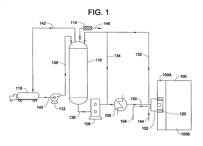
[0041] Figure 1 illustrates a representative renewable fuel oil heating
system.
DETAILED DESCRIPTION
[0042] In 2005, the Environmental Protection Agency (EPA) released its
Renewable Fuel
Standards (RFS), which were the first renewable fuel mandates in the United
States. The RFS
called for 7.5B gallons of renewable fuel to be blended into gasoline by 2012.
Two years later,
the program was expanded under the Energy Independence and Security Act of
(EISA) of 2007 to
target 36B gallons of renewable fuel by 2022. In addition, EISA expanded the
RFS to cover
diesel fuels as well as gasoline (jet fuels were not initially included under
RFS) and established
individual volume targets for the different types of renewable fuel (e.g.,
RFS2 calls for 21B
gallons of advanced biofuels by 2022).
[0043] Cellulosic biofuels falling under RFS2 include diesel fuels, jet
fuels, and heating oils.
Due to the lack of commercial cellulosic facilities in the U.S., the EPA
conducts an annual review
of total cellulosic capacity to evaluate the feasibility of its production
targets and subsequently
makes adjustments. The EPA has proposed cellulosic volumes of up to 12.9M
gallons (up to
15.7M gallons on an ethanol equivalent basis) for 2012, well below its
original 500M gallon
target. Significant progress must be made in facilitating the scale-up of
cellulosic technologies in
order for the U.S. to meet the 16B gallon production target for cellulosic
fuels by 2022.
[0044] Part of the regulations include an incentive program that provides
for an award of
Renewable Identification Numbers (RIN) for the utilization in combustion of
bio-fuels produced
11
CA 02995845 2018-02-15
WO 2017/034981 PCT/US2016/047777
in accordance with certain pathways that are designed to be environmentally
less harmful than the
traditional methods of producing fuels. Among the several approved pathways,
there are some
related to the use of cellulosic containing biomass (cellulosic biomass) that
can earn Cellulosic
Renewable Identification Numbers (C-RN's).
[0045] As of 2014, 31 states had some form of Renewable Portfolio Standard
(RPS) and/or
Alternative Energy Portfolio Standards (APS). A RPS or APS require that
obligated parties
(normally electric utilities) have a certain percentage of their electricity
come from renewable and
alternative resources. The Northeastern United States (including New York) has
led the way with
what are generally accepted to be the most stringent and aggressive standards.
[0046] Traditionally, RPS/APS requirements have only pertained to electric
generators,
though that is beginning to change. In 2013, New Hampshire passed a law that
provided for a
renewable thermal carve-out under their RPS. The rules became effective this
year. In July of
2014, Massachusetts added renewable thermal technologies to the APS2. The
Massachusetts law
went into effect on January 1, 2015. A number of other states are seriously
considering renewable
thermal provisions, as well. This includes Maine, Connecticut, and Rhode
Island, in which
legislations has been proposed, and New York, in which the Public Utilities
Commission can
enact renewable thermal provisions without legislation.
[0047] In both Massachusetts and New Hampshire, obligated parties can
comply with their
applicable law in one of two ways: they can either buy Alternative Compliance
Payments (ACPs)
or buy the credits generated by the renewable thermal generators. In New
Hampshire, the ACP is
set at $25/MWh (2013 dollars) and escalates with inflation. This equates to
about $7.33/MMBtu.
In Massachusetts, the ACP for 2014 was $21.72 and also increases with
inflation. This equates to
about $6.37/MMBtu.
[0048] In both Massachusetts and New Hampshire, the value of the credits is
highly
correlated to the ACP. This is due to the fact that the statutory requirement
of the obligated parties
(i.e., the demand) far exceeds the supply of the credits available to the
marketplace.
[0049] Suitable biomass, biomass materials, or biomass components, include
but are not
limited to, wood, wood residues, sawdust, slash bark, thinnings, forest
cullings, begasse, corn
fiber, corn stover, empty fruit bunches (EFB), fronds, palm fronds, flax,
straw, low-ash straw,
energy crops, palm oil, non-food-based biomass materials, crop residue, slash,
pre-commercial
thinnings and tree residue, annual covercrops, switchgrass, miscanthus,
cellulosic containing
components, cellulosic components of separated yard waste, cellulosic
components of separated
food waste, cellulosic components of separated municipal solid waste (MSW), or
combinations
thereof Cellulosic biomass, for example, includes biomass derived from or
containing cellulosic
materials. For example, the biomass may be one characterized as being
compliant with U.S.
renewable fuel standard program (RFS) regulations, or a biomass suitable for
preparing a
12
CA 02995845 2018-02-15
WO 2017/034981 PCT/US2016/047777
cellulosic-renewable identification number-compliant fuel. In certain
embodiments, the biomass
may be characterized as being compliant with those biomass materials specified
in the pathways
for a D-code 1, 2, 3, 4, 5, 6, or 7-compliant fuel, in accordance with the
U.S. renewable fuel
standard program (RFS) regulations. For example, the biomass may be
characterized as being
compliant with those biomass materials suitable for preparing a D-code 7-
compliant fuel, in
accordance with the U.S. renewable fuel standard program (RFS).
[0050] One aspect of the current application may be to earn Cellulosic
Renewable
Identification Numbers (C-RINs) through the importation or production of a D-
code 7-compliant
unenriched renewable fuel oil and subsequent use as a heating fuel oil in
heating systems (e.g., in
boilers, furnaces, and kilns) to displace use of traditional fossil fuel-based
heating fuel oils (e.g.,
heating fuel oil no. 2 or no. 4).
[0051] One aspect of the current application may be to earn Renewable
Energy Credits
(RECs) through the importation or production of unenriched renewable fuel oil
and subsequent
use in boilers to displace use of traditional heating fuel oils.
[0052] A method of operating an industrial boiler having individually or
collectively one or
more (inclusive of all) of the various embodiment herein described,
comprising: combusting an
unenriched renewable fuel oil and generating (or earning) a thermal energy
credit.
[0053] An industrial boiler (inclusive of dual-purpose and/or dual-fuel
boilers)having
individually or collectively one or more (inclusive of all) of the various
embodiment herein
described, comprising: a burner for combusting an unenriched renewable fuel
oil and generating
(or earning) a thermal energy credit.
[0054] An unenriched renewable heating oil (or renewable fuel oil) prepared
in accordance
with one or more of the governing standards for achieving thermal energy
credits, wherein the
renewable heating oil is derived from biomass. This unenriched renewable
heating oil may be
used in one or more of the various methods, systems, and/or boilers (inclusive
of dual-purpose
and/or dual-fuel boilers).
[0055] One aspect of the current application may be to earn Alternative
Energy Credits
(AECs) through the importation or production of unenriched renewable fuel oil
and subsequent
use in boilers to displace use of traditional heating fuel oils.
[0056] A renewable fuel oil (also referred to herein as "RFO") refers to a
biomass-derived
fuel oil or a fuel oil prepared from the conversion of biomass. For example,
in certain
embodiments, the renewable fuel oil may be a cellulosic renewable fuel oil
(also referred to herein
as "cellulosic RFO"), and may be derived or prepared from the conversion of
cellulosic-
containing biomass. The biomass or cellulosic-containing biomass may be
converted to form a
suitable renewable fuel, by one or more of the following processes: thermal
conversion, thermo-
mechanical conversion, thermo-catalytic conversion, or catalytic conversion of
the biomass or
13
CA 02995845 2018-02-15
WO 2017/034981 PCT/US2016/047777
cellulosic-containing biomass. In certain embodiments, the renewable fuel oil
may be non-
hydrodeoxygenated (non-HDO), non-deoxygenated, non-upgraded, thermally-
processed, rapid
thermally-processed, thermo-mechanically-processed, rapid thermo-mechanically-
processed, non-
hydrotreated, conditioned, and/or combinations thereof. For example, the
renewable fuel oil may
be non-hydrodeoxygenated (non-HDO) renewable fuel oil; a non-HDO, non-
deoxygenated
renewable fuel oil; a rapid thermo-mechanically-processed, non-hydrotreated
renewable fuel oil;
or a non-deoxygenated, non-upgraded, thermally-processed renewable fuel oil. A
further example
of a suitable renewable fuel oil may be a non-hydrodeoxygenated, non-
deoxygenated, non-
hydrotreated, non-upgraded, non-catalytically processed, thermo-mechanically-
processed
renewable fuel oil which would be understood to mean a renewable fuel oil that
may be derived
from simply mechanically grinding a biomass, for example a cellulosic biomass,
and then
thermally processing the ground biomass, for example rapidly, to derive a
liquid with no further
processing steps to substantially alter the oxygen content, the water content,
the sulfur content, the
nitrogen content, the solids content or otherwise enrich the renewable fuel
oil for processing into a
fuel. Additionally, this non-hydrodeoxygenated, non-deoxygenated, non-
hydrotreated, non-
upgraded, non-catalytically processed, thermo-mechanically-processed renewable
fuel oil could
be blended with other batches of non-hydrodeoxygenated, non-deoxygenated, non-
hydrotreated,
non-upgraded, non-catalytically processed, thermo-mechanically-processed
renewable fuel oil
and/or other non-hydrodeoxygenated, non-deoxygenated, non-hydrotreated, non-
upgraded, non-
catalytically processed, thermo-mechanically-processed renewable fuel oil that
have been derived
from other biomass to form blends of non-hydrodeoxygenated, non-deoxygenated,
non-
hydrotreated, non-upgraded, non-catalytically processed, thermo-mechanically-
processed
renewable fuel oil.
[0057] In particular, the renewable fuel oil may be an unenriched renewable
fuel oil: a liquid
formed from a biomass comprising cellulosic material, wherein the only
processing of the
biomass may be a therma-mechanical process (specifically comprising grinding
and rapid thermal
processing, with no post processing, further catalytic processing,
hydrogenation, enrichment of
the liquid or other chemical upgrading prior to introduction into petroleum
conversion unit).
Specifically, no hydrodeoxygenation, no hydrotreating, no catalytic exposure
or contact or
processing just unenriched renewable fuel oil derived by thermo-mechanically
processing
cellulosic containing biomass.
[0058] A preferred renewable fuel oil may be an unenriched liquid (also
referred to as an
unenriched renewable fuel oil) formed from ground-up biomass by a process, for
example rapid
thermal processing, wherein the resulting liquid may be at least 50 wt.%, for
example at least 60
wt.%, at least 70 wt.%, at least 75 wt.%, at 80 wt.% or at least 85 wt.% of
the total weight of the
processed biomass. In other words the liquid yield from the processed biomass
may be at least 50
14
CA 02995845 2018-02-15
WO 2017/034981 PCT/US2016/047777
wt.%, for example at least 60 wt.%, at least 70 wt.%, at least 75 wt.%, at 80
wt.% or at least 85
wt.% of the total weight of the ground biomass being processed. Unenriched
should be
understood to refer to renewable fuel oil liquid that does not undergo any
further pre- or post-
processing including, specifically, no hydrodeoxygenation, no hydrotreating,
no catalytic
exposure or contact or processing. In certain embodiments, unenriched
renewable fuel oil may be
prepared from the ground biomass and then transported and/or stored, and may
be even heated or
maintained at a given temperature; not exceeding 150 F. The mechanical
handling associated
with transporting, storing, heating, and/or pre-heating of the unenriched
renewable fuel oil is not
considered an enriching step. In certain embodiments, an unenriched renewable
fuel oil may
comprise one or more unenriched renewable fuels oils mixed from separate
unenriched batches
and/or unenriched batches resulting from different cellulosic biomass (for
example, several
different types of non-food biomass). In certain embodiments, these mixed
compositions, which
may be blended to purposefully provide or achieve certain characteristics in
the combined
unenriched renewable fuel oil, may still be considered unenriched renewable
fuel oil provided that
substantially all (for example greater than 80 wt.%, or greater than 90 wt.%
such as greater than
95 wt.% or greater than 98 wt.% or greater than 99 wt.%) or all of the
combined batches are
unenriched renewable fuel oil.
[0059] A preferred renewable fuel oil may be a non-HDO renewable fuel oil;
a non-HDO,
non-deoxygenated renewable fuel oil; a rapid thermo-mechanically-processed,
non-hydrotreated
renewable fuel oil; or a non-deoxygenated, non-upgraded, thermally-processed
renewable fuel oil.
[0060] For example, the renewable fuel oil may comprise only thermally
converted biomass
or only thermo-mechanically converted biomass. Suitable renewable fuel oils
may include a
pyrolytic liquid, a thermo-pyrolytic liquid, a thermo-mechanical-pyrolytic
liquid, a rapid thermo-
pyrolytic liquid, or a rapid thermo-pyrolytic-mechanical liquid, derived or
prepared from the
conversion of biomass or cellulosic biomass. In certain embodiments, the
renewable fuel oil may
include a non-hydrodeoxygenated (non-HDO) renewable fuel oil; a non-
deoxygenated renewable
fuel oil; a non-upgraded renewable fuel oil; a thermally-processed cellulosic
renewable fuel oil; a
thermally-processed, non-upgraded-cellulosic renewable fuel oil; a thermally-
processed biomass
liquid; a thermally-processed, non-upgraded-biomass liquid; a thermally
processed non-food-
based biomass liquid; a thermally-processed non-food, cellulosic-based biomass
liquid; a
thermally-processed non-food, renewable liquid; a thermally-processed
cellulosic liquid; a rapid
thermal-processed cellulosic liquid; a rapid thermal-processed bio-oil; a
rapid thermal processed
biomass liquid or thermo-pyrolytic liquid having less than 5 wt.% solid
content, such as less than
4 wt.%, 3 wt.%, 2.5 wt.%, 2 wt.%, 1 wt.%, or less than 0.5 wt.% solid content;
a conditioned
renewable fuel oil; a non-hydrotreated, non-upgraded renewable fuel oil; a
pyrolysis oil or
pyrolytic liquid; a thermo-pyrolysis oil or a thermo-pyrolytic liquid; a bio-
oil or a bio-oil liquid; a
CA 02995845 2018-02-15
WO 2017/034981 PCT/US2016/047777
biocrude oil or biocrude liquid; a thermo-catalytic pyrolysis oil or a thermo-
catalytic pyrolytic oil;
a catalytic pyrolysis oil; a catalytic pyrolytic liquid; or combinations
thereof. For example, in
certain embodiments, the renewable fuel oil may comprise one or more of a non-
hydrodeoxygenated (non-HDO) renewable fuel oil; a non-deoxygenated renewable
fuel oil; a non-
upgraded renewable fuel oil; a thermally-processed cellulosic renewable fuel
oil; a rapid thermo-
mechanically-processed renewable fuel oil; a non-hydrotreated, non-upgraded
renewable fuel oil;
a pyrolysis oil or pyrolytic liquid; or a thermo-pyrolysis oil or a thermo-
pyrolytic liquid.
[0061] In certain embodiments, the thermal conversion process of forming a
suitable
unenriched renewable fuel oil from biomass may include, for example, rapid
thermal conversion
processing. In certain embodiments, the mechanical aspect of the conversion
process (sometimes
referred to herein as "conditioning"), of forming a suitable renewable fuel
from biomass may
include, but may be not limited to drying; grinding; removing fines; removing
tramp metal;
sizing; removing ferrous metals; removing portions of ash; filtering;
screening; cycloning;
mechanically manipulating to remove a substantial portion of solid content; or
combinations
thereof For example, conditioning may include one or more of the following
processes, such as
drying, grinding, removing fines, removing tramp metal, sizing, removing
ferrous metals,
removing portions of ash, filtering, screening, passing through a cyclone,
mechanically
manipulating, contacting with a magnet, or passing through a magnetic field.
In certain
embodiments, the conditioning may further include the addition of water or one
or more alcohols,
such as methanol, ethanol, propanol, isopropyl alcohol, glycerol, or butanol.
For example, the
renewable fuel oil may be conditioned by undergoing filtering, screening,
cycloning, or
mechanical manipulation processes to remove a substantial portion of solid
content. In certain
embodiments, conditioning of the biomass during the conversion to form a
suitable renewable
fuel oil may include removing a portion of carbon from the biomass by
filtering, screening,
cyclone, or mechanically manipulating the biomass. In certain embodiments, the
thermal
conversion process or thermo-mechanical conversion process may comprise a
rapid thermal
conversion process.
[0062] In certain embodiments, the renewable fuel oil may have a pH in the
range of 0.5 to
8Ø For example, the renewable fuel oil may have a pH in the range of 0.5 to
7.0, such as 0.5 to
6.5, 1.0 to 6.0, 2.0 to 5.0, 3.0 to 7.0, 1.0 to 4.0, or 2.0 to 3.5. In certain
embodiments, the pH of
the renewable fuel oil may be less than 8.0, such as less than 7.0, less than
6.5, less than 6.0, less
than 5.5, less than 5.0, less than 4.5, less than 4.0, less than 3.5, less
than 3.0, less than 2.5, or less
than 2Ø In certain embodiments, the pH of the renewable fuel oil may be
altered or modified by
the addition of an external, non-biomass derived material or pH altering
agent. In certain
embodiments, the renewable fuel oil may be acidic. For example, the renewable
fuel oil may
have a pH in the range of between 0.5 to 7, such as between 0.5 to 3, between
1 to 7, between 1 to
16
CA 02995845 2018-02-15
WO 2017/034981 PCT/US2016/047777
6.5, between 2 to 5, between 2 to 3, between 2 to 3.5, between 1 to 4, between
2 to 6, or between
2 to 5. In certain embodiments, the renewable fuel oil has the pH resulting
from the conversion of
the biomass from which it may be derived, such as a biomass-derived pH.
[0063] In certain embodiments, the renewable fuel oil may have a solids
content in the range
less than 5 wt.%. For example, the renewable fuel oil may have a solids
content of less than 4
wt.%, less than 3 wt.%, less than 2.5 wt.%, less than 2 wt.%, less than 1
wt.%, less than 0.5 wt.%,
or less than 0.1 wt.%. In certain embodiments, the renewable fuel oil may have
a solids content in
the range of between 0.005 wt.% and 5 wt.%. For example, the renewable fuel
oil may have a
solids content in the range of between 0.005 wt.% and 4 wt.%, such as between
0.005 wt.% and 3
wt.%, between 0.005 wt.% and 2.5 wt.%, between 0.005 wt.% and 2 wt.%, between
0.005 wt.%
and 1 wt.%, between 0.005 wt.% and 0.1 wt.%, between 0.005 wt.% and 0.5 wt.%,
between 0.05
wt.% and 4 wt.%, between 0.05 wt.% and 2.5 wt.%, between 0.05 wt.% and 1 wt.%,
between 0.05
wt.% and 0.5 wt.%, between 0.5 wt.% and 3 wt.%, between 0.5 wt.% and 1.5 wt.%,
or between
0.5 wt.% and 1 wt.%.
[0064] In certain embodiments, the renewable fuel oil may have an ash
content of less than
0.5 wt.%. For example, the renewable fuel oil may have an ash content of less
than 0.4 wt.%,
such as less than 0.3 wt.%, less than 0.2 wt.%, less than 0.1 wt.%, less than
0.07 wt.%, less than
0.05 wt.%, less than 0.005 wt.%, or less than 0.0005 wt.%. In certain
embodiments, the
renewable fuel oil may have an ash content in the range of between 0.0005 wt.%
and 0.5 wt.%,
such as between 0.0005 wt.% and 0.2 wt.%, between 0.0005 wt.% and 0.05 wt.%,
between 0.0005
wt.% and 0.1 wt.%, between 0.05 wt.% and 0.15 wt.%, or between 0.07 wt.% and
0.12 wt.%.
[0065] In certain embodiments, the renewable fuel oil may comprise a water
content in the
range of between 10-40 wt.%. For example, the renewable fuel oil may comprise
a water content
in the range of between 15 and 35 wt.%, such as between 15 and 30 wt.%,
between 20 and 35
wt.%, between 20 and 30 wt.%, between 30 and 35 wt.%, between 25 and 30 wt.%,
between 20
and 25 wt.%, between 22 and 24 wt.%, or between 32 and 33 wt.% water. In
certain
embodiments, the renewable fuel oil may comprise a water content in the range
of less than 40
wt.%, such as less than 35 wt.%, or less than 30 wt.%. In certain embodiments,
the renewable
fuel oil may comprise a water content of at least 10 wt.%, such as at least 15
wt.%, at least 20
wt.%, or at least 25 wt.%. In certain embodiments, the renewable fuel oil may
comprise a water
content of 23 wt.%. In certain embodiments, the renewable fuel oil may
comprise a water content
of less than 25 wt.%. In certain embodiments, the water content of the
renewable fuel oil may be
in the range of 0.05 wt.% to 40 wt.%. In certain embodiments, the water
content of the renewable
fuel oil (RFO) may be in the range of 20 wt.% to 30 wt.%, 20 wt.% to 25 wt.%,
20 wt.% to 22
wt.%, or 22 wt.% to 25 wt.%, or 25 wt.% to 30 wt.%. For example, the water
content of the
renewable fuel oil (RFO) introduced into the combustion system may be in the
range of 1 wt.% to
17
CA 02995845 2018-02-15
WO 2017/034981 PCT/US2016/047777
35 wt.%, such as 5 wt.% to 35 wt.%, 10 wt.% to 30 wt.%, 10 wt.% to 20 wt.%, 10
wt.% to 15
wt.%, 15 wt.% to 25 wt.%, 15 wt.% to 20 wt.%, 20 wt.% to 35 wt.%, 20 wt.% to
30 wt.%, 20
wt.% to 25 wt.%, 25 wt.% to 30 wt.%, or 30 wt.% to 35 wt.%. In certain
embodiments, the water
content of the renewable fuel oil (RFO) feedstock introduced into a combustion
system may be at
least 23 wt.% such as at least 25 wt.%, at least 28 wt.%, at least 30 wt.%, at
least 31 wt.%, at least
32 wt.%, at least 33 wt.%, or at least 35 wt.%. In certain embodiments, the
water content of the
renewable fuel oil (RFO) feedstock introduced into the combustion system may
be at least 1
wt.%, such as at least 10 wt.%, at least 15 wt.%, at least 20 wt.%, or at
least 30 wt.%. In certain
embodiments, the water content of the renewable fuel oil may be less than 38
wt.%, such as less
than 35 wt.%, less than 34 wt.%, less than 30 wt.%, less than 25 wt.%, less
than 20 wt.%, or less
than 15 wt.%.
[0066] In certain embodiments, the renewable fuel oil may comprise an
oxygen content level
higher than that of a petroleum fraction feedstock, or a fossil fuel for
example a heating fuel oil.
For example, the renewable fuel oil may have an oxygen content level of
greater than 20 wt.%, on
a dry basis or moisture-free basis, such as an oxygen content level in the
range of between 20
wt.% and 50 wt.%, between 35 wt.% and 40 wt.%, between 25 wt.% and 35 wt.%,
between 20
wt.% and 30 wt.%, between 25 wt.% and 50 wt.%, between 20 wt.% and 40 wt.%, or
between 20
wt.% and 35 wt.%, on a dry basis or moisture-free basis.
[0067] In certain embodiments, the renewable fuel oil may comprise a
greater oxygen
content level than carbon content level. For example, the renewable fuel oil
may have a greater
oxygen content level than carbon content level, on a moisture-containing
basis. In certain
embodiments, the renewable fuel oil may have in the range of between 35-80
wt.% carbon content
and in the range of between 20-50 wt.% oxygen content, on a dry basis or
moisture-free basis.
For example, the renewable fuel oil may have in the range of between 50-60
wt.% carbon content
and in the range of between 35-40 wt.% oxygen content, on a dry basis or
moisture-free basis.
[0068] In certain embodiments, the renewable fuel oil may comprise a carbon
content level
of at least 40 wt.% of the carbon content contained in the biomass from which
it may be derived.
For example, the renewable fuel oil may comprise a carbon content level of at
least 45 wt.%, such
as at least 50 wt.%, at least 55 wt.%, at least 60 wt.%, at least 65 wt.%, at
least 70 wt.%, at least
75 wt.%, at least 80 wt.%, at least 85 wt.%, at least 90 wt.%, or at least 95
wt.% of the carbon
content contained in the biomass from which it may be derived. In certain
embodiments, the
renewable fuel oil may comprise a carbon content level in the range of between
40 wt.% and 100
wt.% of the carbon content contained in the biomass from which it may be
derived. For example,
the renewable fuel oil may comprise a carbon content level in the range of
between 40 wt.% and
95 wt.%, between 40 wt.% and 90 wt.%, between 40 wt.% and 80 wt.%, between 50
wt.% and 90
wt.%, between 50 wt.% and 75 wt.%, between 60 wt.% and 90 wt.%, between 60
wt.% and 80
18
CA 02995845 2018-02-15
WO 2017/034981 PCT/US2016/047777
wt.%, between 70 wt.% and 95 wt.%, between 70 wt.% and 80 wt.%, or between 70
wt.% and 90
wt.% of the carbon content contained in the biomass from which it may be
derived. In certain
embodiments, the renewable fuel oil may comprise a carbon content level lower
than that of a
petroleum fraction feedstock. For example, the renewable fuel oil may comprise
a carbon content
level in the range of between 35 wt.% to 80 wt.%, on a dry basis moisture-free
basis, such as
between 40 wt.% to 75 wt.%, between 45 wt.% to 70 wt.%, between 50 wt.% to 65
wt.%,
between 50 wt.% to 60 wt.%, or between 54 wt.% to 58 wt.%, on a dry basis or
moisture-free
basis.
[0069] In certain embodiments, the renewable fuel oil may have a kinematic
viscosity in the
range of 15 cSt to 180 cSt at 40 C, 15 cSt to 30 cSt, 30 cSt to 40 cSt, 40
cSt to 80 cSt, 50 cSt to
70 cSt, 55 cSt to 65 cSt, or 80 cSt to 200 cSt at 40 C.
[0070] By way of example, Tables 1&2 provide analyses of several suitable
unenriched
renewable fuel oils which were prepared according to one or more of the
procedures described in
U.S. Patent No. 7,905,990, U.S. Pat. No. 5,961,786, and U.S. Pat. No.
5,792,340, each of which is
incorporated by reference in their entirety.
19
CA 02995845 2018-02-15
WO 2017/034981 PCT/US2016/047777
TABLE 1 - Analytical Results for Alcell Lignin - Mild Run (LS-3) & Severe Run
(LS-4)
LS-3 LS-4
Volatiles (wtt%) 14.7 27.9
Moisture Content (wt%)) 1.0 0.9
Ash content (wt%) 0.05 IMO
Elemental (wit%, MAF)
Carbon 68.68 73.04
=
Hydrogen 7.16 6.52
Nitrogen 0.00 0.01
=
0)qygen (difference) 24.16 20.43
Hydroxyl (wtt%) 7.54 7.50
Methoxyl (wIt%) 15.68 1.02
Sequential Solubility (wit%)
Diethyl Ether 41.8 40.3
Ethyl Acetate 48.9 42.4
Methanol 0.2 0.6
Residue 9.1 16.7
Fractionatiort (wt%)
,Organic Acids 31.7 3.6
Phenols & Neutrals 45.0 = 81.7
Residue 23.3 14.1
TABLE NOTE: Mild Run (LS-3) was rapid thermal processed at about 500 C and the
Severe Run (LS-4)
was rapid thermal processed at about 700 C
CA 02995845 2018-02-15
WO 2017/034981
PCT/US2016/047777
TABLE 2 Analytical Results of Renewable Fuel Oil Derived from Wood Biomass
LABORATORY
! 1) 1) 2) 3) 3) 4) IIIIIIIAV 'ERRAG
APECIPTC MAVITV 1.19 1.20 1,21 1.217 1.226 1,186 1,160
RATER OONTENT 26 27 21 = 20,6 21 : 28.1 23.9
blr
CHAR CONTENT 2.0 0.6 1.4 : 2,2 6,5 2,2
LI (4 by 4t)
7GHVEANG TI 7267
7310 9245 7525 795$ 653$ 080 7626 I
ELEMENTAL
CHU)
1 CARBON 55.1 53.63 55.5 1 52,8
58.270 51,5
k HYDROGEN 6.7 . 6.06 6.7 6,4 5,5
NITROOP11 0,15 . 0.24 0.1 (0,1 0.39 0.17
0,18 .
SUL rim 0.o2 4zo. 141
O. 07=.001
(1k. by Itt ) 0.13 0, 15 0.22 0,13
0,16
. _
TABLE NOTES: The RFO derived from the Wood Biomass was analyzed by the
following labs: 1)
Universite Catholique de Louvain, Belgium; 2) ENEL, Centro Ricerca Termica,
Italy; 3) VTT, Laboratory
of Fuel and Process Technology, Finland; 4) CANMET, Energy Research
Laboratories, Canada; 5)
Commercial Testing and Engineering Co., U.S.A.
[0071] In certain embodiments, the renewable fuel oil may comprise an
energy content level
of at least 30% of the energy content contained in the biomass from which it
may be derived. For
example, the renewable fuel oil may comprise an energy content level of at
least 45 %, such as at
least 55%, at least 60%, at least 65%, at least 70%, at least 75%, at least
80%, at least 85%, at
least 90%, or at least 95% of the energy content contained in the biomass from
which it may be
derived. In certain embodiments, the renewable fuel oil may comprise an energy
content level in
the range of between 50% and 98% of the energy content contained in the
biomass from which it
may be derived. For example, the renewable fuel oil may comprise a energy
content level in the
range of between 50 % and 90%, between 50% and 75%, between 60% and 90%,
between 60%
and 80%, between 70% and 95%, between 70% and 80%, or between 70% and 90% of
the energy
content contained in the biomass from which it may be derived.
[0072] In certain embodiments, the renewable fuel oil may comprise an
energy content level
lower than that of a petroleum fuel. For example, the renewable fuel oil may
comprise a energy
content level in the range of between 30-95 %, on a dry basis (moisture-free
basis), relative to the
energy content of a petroleum feedstock, such as between 40-90%, between 45-85
%, between 50-
80 %, between 50-60 %, or between 54-58 %, on a dry basis or moisture-free
basis, relative to the
energy content of a petroleum feedstock. In certain embodiments, the renewable
fuel oil may
have an energy content in the range of between 30-90%, relative to the
petroleum fraction
feedstock energy content. For example, the renewable fuel oil may have an
energy content of
21
CA 02995845 2018-02-15
WO 2017/034981 PCT/US2016/047777
35%, 40%, 45%, 50%, 55%, 60%, 65%, 70%, 75%, 80%, or 85%, relative to the
petroleum
fraction feedstock energy content.
[0073] According to one embodiment, the renewable oil includes all of the
whole liquid
produced from the thermal or catalytic conversion of biomass, with preferably
low water content.
Alternatively, whole liquid produced from the thermal or catalytic conversion
of biomass may be
phase separated to provide a predominately non-aqueous fraction as the
feedstock for refinery
systems. In addition, fractions can be taken from the unit operations of the
downstream liquid
collection system of thermal or catalytically converted biomass such as a
primary condenser
means, a secondary condenser, demister, filter, or an electrostatic
precipitator.
[0074] According to one embodiment, the flash point of a renewable oil may
be increased to
reduce the volatile content of the liquid. According to one embodiment, the
flash point of a
renewable oil may be increased to reduce the volatile content of the liquid
and subsequently co-
processed in an FCC with a petroleum feedstock. The flash point would be
increased above the
range of 55-62 C as measured by the Pensky-Martens closed cup flash point
tester (e.g. ASTM
D-93). Various methods and apparatus can be used to effectively reduce the
volatile components,
such as wiped film evaporator, falling film evaporator, flash column, packed
column,
devolatilization vessel or tank. Reduction of the some of the volatile
components of the
renewable can help to reduce components such as phenols.
[0075] According to one embodiment a renewable fuel oil may be blended with
vegetable
based oils, as well as alcohols including methanol and ethanol, with or
without a surfactant, prior
to use in a combustion system.
[0076] In certain embodiments, the method includes utilizing a renewable
fuel oil to generate
heat to warm buildings or other facilities where people live, work, recreate
or conduct other
activity.
[0077] A representative renewable fuel oil heating system is illustrated in
FIG. 1. According
to this embodiment, a supply of renewable fuel oil is delivered by tanker
truck 116. Renewable
fuel oil is pumped via storage fill pump 112 through transfer lines 138 and
140 into storage tank
110. Vapors present in storage tank 110 are displaced through vapor return
line 142 and/or
conservation valve line 146. Carbon filter 114 may be in communication with
conservation valve
line 146 to capture certain compounds present in the vapor, for example
sotolon. Vapors
transferred through vapor return line 142 are sequestered in tanker truck 116.
[0078] Renewable fuel oil is transferred from storage tank 110 by positive
displacement
pump 108. To maintain constant temperature and phase stability of the stored
renewable fuel oil,
a portion of the renewable fuel oil is recirculated by recirculation lines 132
and 134. To affect the
aforementioned temperature maintenance, a portion of recirculated renewable
fuel oil passed
through heat exchanger 106 to heat renewable fuel oil portion 132 before
return to storage tank
22
CA 02995845 2018-02-15
WO 2017/034981 PCT/US2016/047777
110. A typical heat exchanger 106 might comprise a shell and tube exchanger
utilizing hot water
as a heat source.
[0079] In the representative embodiment illustrated in FIG. 1, a portion of
heated renewable
fuel oil 130 is supplied to burner 102, where renewable fuel oil undergoes
combustion with air
supplied by air feed 144. The combustion flame is directed to firebox 100A of
boiler 100. Heat
transfer from firebox 100A to boiler tubes 100B generates steam for use in
heating applications.
[0080] The representative embodiment illustrated in FIG. 1 includes a
second fuel source
104, for example heating fuel oil no. 4, which may be combusted instead of
renewable fuel oil in
the event of a temporary interruption in the supply of renewable fuel oil 130.
[0081] The representative embodiment illustrated in FIG. 1 includes heat
sink 120 placed in
the firebox 100A for absorbing, radiating and/or reflecting heat, for example
an extended burner
block with a cylindrical orifice or an assembly of refractory bricks placed in
close proximity of
the combusting renewable fuel oil. Heat sink 120 may be positioned to radiate
and/or reflecting
sufficient heat to promote vaporization and/or ignition of the renewable fuel
oil and/or maximize
combustion and/or restart combustion of the renewable fuel oil in the event of
a flame-out.
[0082] In certain embodiments, the method includes utilizing a renewable
fuel oil to produce
one or more cellulosic renewable identification numbers such as a D-code 7-
compliant renewable
identification number.
[0083] In certain embodiments, a series of renewable fuel oil shipments
made by tanker truck
are supplied to a storage tank in communication with a combustion or thermal
system. In certain
embodiments, each shipment originates from a facility that produces an
unenriched renewable
fuel oil by rapid thermal processing. In certain embodiments, the temperature
of the unenriched
renewable fuel oil is adjusted prior to shipment in the tanker truck to a
specified temperature, such
as a temperature in the range of 10 C to 40 C, 10 C to 20 C, 10 C to 30 C, 20
C to 30 C, 30
C to 40 C, 20 C to 40 C, 20 C to 30 C, or 30 C to 40 C. In certain
embodiments, the
temperature of a renewable fuel oil, for example an unenriched renewable fuel
oil, is maintained
at an approximately constant temperature throughout loading of the renewable
fuel oil, for
example an unenriched renewable fuel oil, from a production facility onto a
tanker truck,
transport, offloading and storage, for example in a storage tank. In certain
embodiments, a series
of unenriched renewable fuel oil shipments are supplied to a storage tank in
communication with
a combustion system. In certain embodiments, the renewable fuel oil in each of
the series of
shipments has a water content, measured as a weight percentage, subject to a
quality control
requirement that specifies the water content will vary by no more than a
specified percentage
among shipments. For example, the renewable fuel oil in each of the series of
shipments may
have a water content specified to vary by no more than 1%, 2%, 3%, 4%, or 5%
among the series
of shipments. In certain embodiments, the series of deliveries must be
completed within one
23
CA 02995845 2018-02-15
WO 2017/034981
PCT/US2016/047777
week, two weeks, one month, two months, three months, or six months. In
certain embodiments,
the renewable fuel oil is an unenriched renewable fuel oil.
[0084] In
certain embodiments, the invention relates to a method of transferring a
shipment
of renewable fuel oil from a tanker truck to a storage tank in communication
with a combustion or
thermal system. In certain embodiments, the invention relates to a method of
transferring a
shipment of unenriched renewable fuel oil from a tanker truck to a storage
tank in communication
with a combustion or thermal system. In certain embodiments, the combustion
system comprises
a boiler, a furnace, a kiln, and/or an evaporative cooling system. In certain
embodiments, the
invention relates to a method of transferring a shipment renewable fuel oil
from a tanker truck to a
storage tank in communication with a boiler. In certain embodiments, the
invention relates to a
method of transferring a shipment of unenriched renewable fuel oil from a
tanker truck to a
storage tank in communication with a boiler. In certain embodiments, the
invention relates to a
method of transferring a shipment of renewable fuel oil from a tanker truck to
a storage tank in
communication with a combustion or thermal system, wherein the renewable fuel
oil is
transferred at an approximately constant temperature. For example, the
temperature of the
renewable fuel oil may be maintained at an approximately constant temperature
during transfer in
the range of 10 C to 40 C, 10 C to 20 C, 10 C to 30 C, 20 C to 30 C, 30
C to 40 C, 20 C
to 40 C, 20 C to 30 C, or 30 C to 40 C. In certain embodiments, the
invention relates to a
method of transferring a shipment of renewable fuel oil from a tanker truck to
a storage tank in
communication with a combustion or thermal system, wherein the renewable fuel
oil is
transferred at an temperature within a specified range relative to the
temperature of any renewable
fuel oil initially present in the storage tank. For example, the renewable
fuel oil may be
transferred at a temperature that is within 1 C, 2 C, 3 C, 4 C, or 5 C of
the temperature of any
renewable fuel oil initially present in the storage tank.
[0085] In
certain embodiments, the invention relates to a method of transferring a
shipment
of renewable fuel oil from a tanker truck to a storage tank in communication
with a combustion
system, comprising collecting the vapors displaced by the addition of the
renewable fuel oil to the
storage tank in the tanker truck. In certain embodiments, the invention
relates to a method of
transferring a shipment of unenriched renewable fuel oil from a tanker truck
to a storage tank in
communication with a combustion system, comprising collecting the vapors
displaced by the
addition of the renewable fuel oil to the storage tank in the tanker truck. In
certain embodiments,
the invention relates to a method of transferring a shipment of renewable fuel
oil from a tanker
truck to a storage tank in communication with a combustion system, wherein
substantially all of
the vapors are collected in the tanker truck. In certain embodiments, no more
than an
insignificant quantity of the vapors displaced by the addition of the
renewable fuel oil to the
storage tank is emitted to the atmosphere during transfer. In certain
embodiments, the tank is
24
CA 02995845 2018-02-15
WO 2017/034981
PCT/US2016/047777
equipped with a conservation vent equipped with a carbon filter. In certain
embodiments, the
carbon filter comprises activated carbon or charcoal. In certain embodiments,
the conservation
vent is not opened during the transfer of vapors from the storage tank to the
tanker truck. In
certain embodiments, the total lifetime and/or the life of the carbon filter
between recharging is
increased relative to a transfer of the renewable fuel oil wherein the
displaced vapors are not
sequestered in the tanker truck. For example, the total lifetime and/or the
life of the carbon filter
between recharging may be increased by 50%, 100%, 200%, 500% and 1000%. In
certain
embodiments, the vapors collected in the tanker truck may be removed from the
storage site. In
certain embodiments, the vapors collected in the tanker truck are odorous. In
certain
embodiments, the vapors collected in the tanker truck comprise sotolon. In
certain embodiments,
In certain embodiments, pressure in the storage tank during transfer of a
shipment of renewable
fuel oil does not change by more than a specified threshold, such as 1 psig, 3
psig, or 5 psig
[0086] In certain embodiments, the invention relates to a system for
transferring a shipment
of renewable fuel oil from a tanker truck to a storage tank in communication
with a combustion
system. In certain embodiments, the invention comprises transfer hosing,
transfer piping and a
transfer pump to transfer a shipment of renewable fuel oil from a tanker truck
to a storage tank, a
storage tank with return piping and return hosing capable of attaching to the
tanker truck, and a
conservation valve equipped with a carbon filter. In certain embodiments, the
transfer piping, the
return piping, and the conservation valve connect at the top of the storage
tank. In certain
embodiments, the transfer piping, the return piping, and/or the transfer pump
are constructed of
suitable materials for containing the renewable fuel oil without corrosion. In
certain
embodiments, the transfer piping, the return piping, and/or components of the
transfer pump are
lined with a suitable elastomer for containing the renewable fuel oil without
corrosion. In certain
embodiments, the transfer piping, the return piping, and/or components of the
transfer pump are
constructed of metal alloys where required to prevent corrosion. In certain
embodiments, the
transfer piping, the return piping, and/or components of the transfer pump are
constructed of 304
or 316 stainless steel to prevent corrosion. In certain embodiments, the
return piping and the
return hosing are sized such that less than a specified percentage of any
vapors displaced from the
storage tank during the transfer of the renewable fuel oil pass through the
carbon filter, for
example less than 5%, 10%, 15%, or 20% of the displaced vapors.
[0087] In certain embodiments, the storage tank may be self-contained,
double-walled, lined
with elastomer, and/or constructed of 304 or 306 stainless steel. In certain
embodiments, the
storage tank may be a bunker tank. In certain embodiments, the storage tank
may contain a
supply of fuel for up to a specified period of time. For example, the storage
tank may contain a
supply of fuel for up to one week, two weeks, one month, three months, six
months, or one year.
CA 02995845 2018-02-15
WO 2017/034981 PCT/US2016/047777
[0088] In certain embodiments, the invention relates to a method, system,
or apparatus for
avoiding phase separation of the renewable fuel oil stored in the storage tank
for combustion in a
combustion system. In certain embodiments, the renewable fuel oil stored in
the storage tank may
be agitated in the storage tank. In certain embodiments, the renewable fuel
oil stored in the
storage tank may be agitated by a operating a mixer such as a mechanical
impeller located in the
storage tank. In certain embodiments, the renewable fuel oil stored in the
storage tank may be
agitated by recirculating a specified percentage of the renewable fuel oil per
unit time tough an
external pump. For example, the percentage of stored renewable fuel oil
recirculated per hour
may be in the range of 0% to 100%, for example 0 % to 50%, 0% to 25%, 25% to
50%, 50% to
75%, or 50% to 100%; the percentage of stored renewable fuel oil recirculated
per hour may be
less than 10%, for example less than 5%, less than 2%, or less than 1%. In
certain embodiments
the pumping is performed by a renewable fuel oil delivery pump in fluid
communication with the
storage tank.
[0089] In certain embodiments, the invention relates to a method for
maintaining a
renewable fuel oil stored in the storage tank for combustion in a combustion
system at a relatively
constant temperature. For example, the method may maintain the temperature
within 2%, 5%, or
10% of the average temperature of the renewable fuel oil stored in the storage
tank. In certain
embodiments, the temperature of the renewable fuel oil is maintained at a
relatively constant
temperature in the storage tank by dynamically recirculating, or simply
recirculating, a specified
percentage per unit time and warming or cooling the recirculating portion of
the renewable fuel
oil. For example, the percentage of stored renewable fuel oil recirculated per
hour may be in the
range of 0% to 100%, for example 0 % to 50%, 0% to 25%, 25% to 50%, 50% to
75%, or 50% to
100%. In certain embodiments, the invention relates to a method, apparatus, or
system for
maintaining a renewable fuel oil stored for combustion in a combustion system
at a relatively
constant temperature by pumping a portion of the renewable fuel oil through an
external heat
exchanger whose outlet is in fluid communication with the storage tank. In
certain embodiments
the pumping is performed by a renewable fuel oil delivery pump in fluid
communication with the
storage tank and the external heat exchanger. In certain embodiments the
renewable fuel oil
delivery pump is a positive displacement pump. In certain embodiments the
renewable fuel oil
delivery pump is a gear pump, piston pump, or a diaphragm pump. In certain
embodiments the
external heat exchanger is a renewable fuel oil heater. In certain embodiments
the renewable fuel
oil heater utilizes hot water as a heat transfer fluid. In certain embodiments
the renewable fuel oil
heater is a shell and tube heat exchanger. In certain embodiments the
renewable fuel oil heater
and the renewable fuel oil delivery pump are constructed of corrosion
resistant materials. For
example, the renewable fuel oil heater and the renewable fuel oil delivery
pump may each
26
CA 02995845 2018-02-15
WO 2017/034981 PCT/US2016/047777
comprise a corrosion resistant elastomer and/or corrosion resistant metal
alloy (for example, 304
or 316 stainless steel).
[0090] For example, the method may maintain the temperature within 2%, 5%,
or 10% of
the average temperature of the renewable fuel oil stored in the storage tank.
In certain
embodiments, the temperature of the renewable fuel oil is maintained at a
relatively constant
temperature in the storage tank by dynamically recirculating a specified
percentage per unit time
and warming or cooling the recirculating portion of the renewable fuel oil.
For example, the
percentage of stored renewable fuel oil recirculated per hour may be in the
range of 0% to 100%,
for example 0 % to 50%, 0% to 25%, 25% to 50%, 50% to 75%, or 50% to 100%.
[0091] In certain embodiments, the invention relates to a method,
apparatus, or system for
maintaining a renewable fuel oil stored for combustion in a combustion system
at a relatively
constant temperature by pumping a portion of the renewable fuel oil through an
external heat
exchanger whose outlet is in fluid communication with the storage tank. In
certain embodiments
the pumping is performed by a renewable fuel oil delivery pump in fluid
communication with the
storage tank and the external heat exchanger. In certain embodiments the
renewable fuel oil
delivery pump is a positive displacement pump. In certain embodiments the
renewable fuel oil
delivery pump is a gear pump, piston pump, or a diaphragm pump. In certain
embodiments the
external heat exchanger is a renewable fuel oil heater. In certain embodiments
the renewable fuel
oil heater utilizes hot water as a heat transfer fluid. In certain embodiments
the renewable fuel oil
heater is a shell and tube heat exchanger. In certain embodiments the
renewable fuel oil heater
and the renewable fuel oil delivery pump are constructed of corrosion
resistant materials. For
example, the renewable fuel oil heater and the renewable fuel oil delivery
pump may each
comprise a corrosion resistant elastomer and/or a corrosion resistant metal
alloy (for example, 304
or 316 stainless steel). In certain embodiments, the invention relates to an
apparatus or system
comprising a process controller and temperature control valve in fluid contact
with the renewable
fuel oil heater and the storage tank, wherein the process controller maintains
the renewable fuel
oil stored for combustion in a combustion system at a relatively constant
temperature by adjusting
the temperature control valve and or the rate of heat transfer fluid.
[0092] In certain embodiments, the invention relates to a method of
combusting a renewable
fuel oil wherein the renewable fuel oil is pre-heated to a specified
temperature and the heated
renewable fuel oil is pumped to a fuel delivery train in a combustion system.
For example the
renewable fuel oil may be pre-heated to a temperature in the range of 50 C to
80 C, for example
50 C to 70 C, 50 C to 55 C, 55 C to 60 C, 60 C to 65 C, 65 C to 70
C, or 75 C to 80 C.
In certain embodiments, the invention relates to a method, system, and/or
apparatus for pre-
heating a renewable fuel oil prior to combustion by pumping the renewable fuel
oil through a
renewable fuel oil heater in fluid contact with a fuel delivery train in a
combustion system. In
27
CA 02995845 2018-02-15
WO 2017/034981
PCT/US2016/047777
certain embodiments, the renewable fuel oil heater is heated by combustion of
a separate portion
of the renewable fuel oil.
[0093] In certain embodiments, the invention relates to a method of
combusting a renewable
fuel oil wherein the renewable fuel oil is pumped by a renewable fuel oil pump
from a storage
tank to a fuel delivery train at a specified pressure. For example, the
renewable fuel oil may be
delivered to the fuel delivery train at a pressure of 100 psig, 60 psig to 80
psig, 80 psig to 100
psig, 100 psig to 120 psig, or 120 psig to 140 psig In certain embodiments,
the invention relates
to an apparatus or system comprising a process controller and pressure control
valve in fluid
contact with the renewable fuel oil pump and the storage tank, wherein the
process controller
maintains the specified pressure by adjusting the pressure control valve
and/or the speed of the
renewable fuel oil pump.
[0094] In certain embodiments, the invention includes a combustion system.
In certain
embodiments, the combustion system present includes an apparatus, and a method
of using the
same, for example a boiler. In certain embodiments, the boiler or combustion
system comprises a
boiler, a furnace, a kiln, and/or an evaporative cooling system. In certain
embodiments, the
combustion system may be a commercial boiler. In certain embodiments, the
boiler or
combustion system may be an industrial boiler. In certain embodiments, the
boiler may be a fire-
tube boiler. In certain embodiments, the boiler may be a water-tube boiler. In
certain
embodiments, the boiler may meet a specified BTU demand or thermal load. For
example, the
boiler may deliver more than 1 MMBtu per hour, 2 MMBtu per hour, 3 MMBtu per
hour, 4
MMBtu per hour, 5 MMBtu per hour, 6 MMBtu per hour, 7 MMBtu per hour, 8 MMBtu
per
hour, 10 MMBtu per hour, or 20 MMBtu per hour. In certain embodiments, the
boiler may have
an efficiency of at least 70%, at least 80%, at least 85%, at least 88%, or at
least 89%, as
measured by the input-output method and/or the heat loss method. In certain
embodiments, the
boiler may have an efficiency of between 70% and 99.999%, for example, 70% and
75%, 75%
and 80%, 80% and 85%, 85% and 90%, 90% and 95%, or 95% and 99.999%, as
measured by the
input-output method and/or the heat loss method. If the input-output method is
used, the boiler
efficiency computation may use the higher heating value or the lower heating
value of the fuel.
[0095] In certain embodiments, the invention includes a boiler system, a
boiler apparatus,
and a method of using the same. In certain embodiments, the boiler system may
comprise a fire
box, a burner system, a refractory or heat sink component for absorbing,
radiating and/or
reflecting heat, a supply of fuel, a supply of air, and a control system. In
certain embodiments,
the supply of fuel may comprise a renewable fuel oil. In certain embodiments,
the supply of fuel
may comprise an unenriched renewable fuel oil. In certain embodiments, the
supply of fuel may
comprise a petrochemical or fossil fuel, for example a heating fuel oil or a
diesel fuel. In certain
embodiments, the supply of air may comprise a stream of atomization air and a
stream of
28
CA 02995845 2018-02-15
WO 2017/034981 PCT/US2016/047777
combustion air. In certain embodiments, the boiler system may comprise a
stream of atomization
steam. In certain embodiments, the boiler is firetube boiler. In certain
embodiments, the firetube
boiler comprises a soot blowing system. In certain embodiments the soot
blowing system
provides pulses of compressed air to the fire tubes of the firetube boiler on
a pre-determined
schedule or a pre-determined frequency. In certain embodiments, the compressed
air is at a
pressure of 50 psig, 75 psig, 100 psig, 125 psig, 150 psig, or between 90 psig
and 110 psig. In
certain embodiments, the pulses of compressed air last less than 1 second,
less than 2 seconds,
less than 3 seconds, less than 5 seconds, or a few seconds. In certain
embodiments, the pre-
determined schedule or predetermined frequency comprises 1 cycle per day, 4
cycles per day, 8
cycles per day, or between 1 and 12 cycles per day. In certain embodiments,
the pre-determined
frequency is at least every 15 minutes, for example every 15 minutes, or at
least once per day, for
example every 30 minutes, every 60 minutes, every 90 minutes, every 2 hours,
every 3 hours,
every 6 hours or every 12 hours. In certain embodiments, a cycle comprises
delivering pulses of
compressed air simultaneously. In other embodiments, a cycle comprises
delivering pulses of
compressed air to the firetubes in a pre-determined sequence.
[0096] In certain embodiments, the boiler system may comprise one or more
boiler control
systems. In certain embodiments, the boiler control system may control the
rate of feed supplied
to the burner in order to maintain a relatively constant boiler steam
pressure. In certain
embodiments, the boiler control system may control the rate of addition of
combustion air to the
burner in order to maintain a relatively constant oxygen concentration in the
flue gas.
[0097] The burner system may be comprised of any type of burner suitable
for use in a
boiler. In certain embodiments, the burner system may comprise a fuel train, a
burner, and a
safety fuel shut-off valve. In certain embodiments, the burner may comprise a
fuel gun, an
atomization assembly, a nozzle, and a combustion air supply. In certain
embodiments, the burner
system may comprise an atomization air supply. In certain embodiments, the
burner system may
comprise an atomization steam supply. In certain embodiments, the burner may
utilize internal
atomization. In certain embodiments, the burner may utilize internal
atomization by combining
fuel with a gas, for example steam or air. In certain embodiments, the burner
may utilize external
atomization. In certain embodiments, the nozzle may be made of a stainless
steel or brass. In
certain embodiments, the safety fuel shut-off valve may be a block valve. In
certain
embodiments, the burner system is capable of maintaining combustion of a
renewable fuel oil at a
temperature of 1,500 C to 2,000 C. In certain embodiments, the burner system
is capable of
maintaining combustion of a renewable fuel oil having an adiabatic flame
temperature of 1,300 C
to 1,800 C. In certain embodiments, the burner system may have a pilot
lighting system. In
certain embodiments, the pilot lighting system may be a propane lighting
system. In certain
29
CA 02995845 2018-02-15
WO 2017/034981 PCT/US2016/047777
embodiments, the pilot lighting system may be intermittent, or may activate
only when ignition of
the fuel is required and shut off after a combustion flame is established.
[0098] In certain embodiments, the burner system may be a dual-use or dual-
fuel burner
system, for example a burner system capable of being controlled to combust any
one of at least
two supplies of fuel or two different fuels. In certain embodiments, the
burner system is
controlled to combust any one of at least two different fuels at predetermined
flow rates. In
certain embodiments, the burner system is controlled to combust any one of at
least two different
fuels to meet a dynamic or a predetermined heating demand. For example, the
burner system
may be capable of combusting a heating fuel oil fuel and a renewable fuel oil.
In certain
embodiments, the invention relates to a method of combustion wherein the
burner system burns a
first fuel at a first specified volumetric flow rate, temperature and air to
fuel ratio and a second
fuel at a second specified volumetric flow rate, temperature and air to fuel
ratio. For example, the
burner system may combust a heating oil at a temperature of 1,900 to 2,300 C
with an atomized
fuel-to-air ratio of 0.8:1 to 5:1 and burning a second fuel in the burner at a
temperature of 1,300 to
1,800 C with an atomized fuel-to-air ratio of 0.4:1 to 4:1. For example, the
burner system may
combust a heating fuel oil having an adiabatic flame temperature of 1,900 to
2,300 C with a fuel-
to-air ratio of 0.8:1 to 5:1 and burning a second fuel in the burner having an
adiabatic flame
temperature of 1,300 to 1,800 C with an fuel-to-air ratio of 0.4:1 to 4:1. In
certain embodiments,
the invention relates to a method of combustion, comprising burning a first
fuel in a burner with
an adiabatic flame temperature of 1,900 to 2,300 C and a fuel-to-air ratio
resulting in 1%, 2%,
3%, 4%, or between 2% and 4% oxygen in the combustion flue gas, and burning a
second fuel in
the burner with an adiabatic flame temperature at least 300 C below that of
the first fuel and an
fuel-to-air ratio resulting in 1%, 2%, 3%, 4%, or between 2% and 4% oxygen in
the combustion
flue gas produced by combustion of the second fuel.
[0099] In certain embodiments, the invention relates to burning a renewable
fuel oil (RFO)
with excess air such that there is a 1%, 2%, 3%, 4%, or between 2% and 4%
excess oxygen on a
stoichiometric basis in the mixture of fuel and air. In certain embodiments,
the invention relates
to burning a renewable fuel oil (RFO) with excess air such that there is 1
vol.%, 2 vol.%, 3 vol.%,
4 vol.%, between 2 vol.% and 4 vol.%, or between 3 vol.% and 6 vol.% oxygen in
the combustion
flue gas following combustion.
[00100] In certain embodiments, the invention relates to burning a
renewable fuel oil (RFO) to
produce a combustion flue gas comprising nitrogen oxides (NO), carbon
monoxide, sulfur oxides
(SO), and particulate matter (PM). In certain embodiments, the concentration
of NO in the
combustion flue gas is less than 375 ppm, less than 225 ppm, less than 150
ppm, less than 110
ppm, or less than 75 ppm. In certain embodiments, the concentration of CO in
the combustion
flue gas is less than 50 ppm, less than 30 ppm, less than 20 ppm, less than 15
ppm, or less than 10
CA 02995845 2018-02-15
WO 2017/034981 PCT/US2016/047777
ppm. In certain embodiments, the concentration of SOõ in the combustion flue
gas is less than 1
ppm, less than 0.5 ppm, or less than 0.2 ppm. In certain embodiments, the PM
generated is less
than 0.5 lb/MMBtu, less than 0.3 lb/MMBtu, less than 0.2 lb/MMBtu, less than
0.15 lb/MMBtu,
or less than 0.1 lb/MMBtu.
[00101] In certain embodiments, the a renewable fuel oil (RFO) has a lower
adiabatic flame
temperature than a petroleum-based fuel. In certain embodiments, the adiabatic
flame
temperature of the second fuel is at least 200 C, 300 C, 400 C, 500 C, 600
C, or between 100
C and 1000 C below the adiabatic flame temperature of the first fuel.
[00102] In certain embodiments, the burner system may comprise a start-up
burner fuel
bypass line in fluid contact with a storage tank.
[00103] In certain embodiments, the burner system may comprise a post-
combustion purge
system. In certain embodiments, the post-combustion purge system may be
located between a
safety fuel shut-off valve and an orifice of the burner. In certain
embodiments, post-combustion
purge system may be capable of removing substantially all of the residual fuel
between the safety
fuel shut-off valve and an orifice of the burner within a specified period of
time after the safety
fuel shut-off valve closes. For example, post-combustion purge system may be
capable of
removing greater than 85% of the residual fuel between the safety fuel shut-
off valve and the
orifice within 2 seconds, 5 seconds, 10 seconds, 15 seconds, 20 seconds, or 30
seconds after the
safety fuel shut-off valve closes.
[00104] In certain embodiments, the invention relates to a post-combustion
purge method of
purging the burner system of residual fuel during and/or after shutdown. In
certain embodiments,
the post-combustion purge method reduces or prevents formation of coke in the
burner. In certain
embodiments, the post-combustion purge method reduces or eliminates odors
caused if residual
fuel smolders in the burner, for example the Morrison tube of a boiler, and/or
a combustion space
such as a fire box. In certain embodiments, the post-combustion purge method
comprises
blowing compressed air through a fuel line to cause residual fuel located
between a safety fuel
shut-off valve and an orifice of the burner to discharge into a combustion
space, for example a fire
box. In certain embodiments, the discharged residual fuel may be combusted in
the fire box. In
certain embodiments, the post-combustion purge method comprises pumping
residual fuel out of
the fuel region located between a safety fuel shut-off valve and an orifice of
the burner. In certain
embodiments, the post-combustion purge method utilizes a scavenger pump
located at the inlet
side of the burner to suck residual fuel out of the fuel region located
between a safety fuel shut-off
valve and an orifice of the burner. In certain embodiments, the post-
combustion purge method
delivers the residual fuel to a storage tank.
[00105] In certain embodiments, the refractory or heat sink component for
absorbing,
radiating and/or reflecting heat is positioned in combustion space, for
example in a boiler fire box
31
CA 02995845 2018-02-15
WO 2017/034981 PCT/US2016/047777
proximate a pre-determined flame zone. In certain embodiments, the refractory
or heat sink
component is positioned proximate an atomized stream of fuel and air, for
example in a boiler fire
box proximate an atomized stream of fuel and air. In certain embodiments, the
refractory or heat
sink component is a pre-formed burner block. In certain embodiments, the
refractory or heat sink
component is a cylindrical or tube-shaped orifice formed of ceramic,
refractory brick, refractory
tile, or a suitable metal such as a stainless steel. In certain embodiments,
the refractory or heat
sink component is a retrofit or an extension to a pre-existing refractory
component, for example a
burner sleeve 1 inch to 3 inches in length. In certain embodiments, the heat
sink component is a
cylindrical or tube-shaped heat sink component that extends to shield at least
25% of the flame
length in the direction of the flame. In certain embodiments, the cylindrical
or tube-shaped heat
sink component has a length-to-average diameter ratio of between 1:1 and 3:1,
or between 1.5:1
and 2.5:1, or 2:1. In certain embodiments, the cylindrical or tube-shaped heat
sink is 4 inches to
60 inches in length, for example 8 inches to 16 inches in length, or 40 inches
to 60 inches in
length.
[00106] In certain embodiments, the heat sink component reflects sufficient
heat from the
combustion flame and/or generates sufficient radiation to promote vaporization
and ignition of the
atomized renewable fuel oil, and/or to increase combustion of the atomized
stream, and/or to
restart the atomized stream of fuel after flame-out. In certain embodiments,
the heat sink
component shortens the distance from the burner nozzle to the point of
ignition of the flame.
EXAMPLES
[00107] Example 1
[00108] A sample unenriched renewable fuel oil (RFO) feedstock was produced
from rapid
thermal processing of a wood residue feedstock in a commercial fast pyrolysis
process, according
to any one of U.S. Patent No. 7,905,990, U.S. Pat. No. 5,961,786, and U.S.
Pat. No. 5,792,340,
each of which is herein incorporated by reference in their entirety. The
properties of the
renewable fuel oil (RFO) feedstock are summarized in Table 3.
32
CA 02995845 2018-02-15
WO 2017/034981 PCT/US2016/047777
TABLE 3
Parameter Test Method RFO
Water Content, wt.% ASTM E203 26.98%
Viscosity @ 40 C, cSt ASTM D445 58.9
Ash Content, wt.% EN 055 0.02%
Solids Content, wt.% ASTM D7579 0.04%
Density @ 20 C, kg/dm3 EN 064 1.1987
pH ASTM E70-07 2.44
Carbon Content, wt.% as is ASTM D5291 41.80%
Hydrogen Content, wt.% as is ASTM D5291 7.75%
Nitrogen Content, wt.% as is ASTM D5291 0.28%
Sulfur Content, wt.% as is ASTM D5453 0.01%
Oxygen Content, wt.% as is By Difference 50.14%
1-11-1V (as is), cal/g ASTM D240 4093.8
1-11-1V (as is), MJ/kg ASTM D240 17.1
1-11-1V (as is), BTU/lb ASTM D240 7369
[00109] Example 2
[00110] An unenriched renewable fuel oil (RFO) was used to fire a
retrofitted Cleaver Brooks
CB-1-600-200-015 fire tube boiler (dual-fuel boiler). Table 4 gives
compositional analysis of the
unenriched renewable fuel oil (RFO).
TABLE 4
Parameter Test Method RFO
Ash Content, wt.% ASTM D482 0.11%
Carbon Content, wt.% as is ASTM D5291 43.0%
Hydrogen Content, wt.% as is ASTM D5291 7.72%
Nitrogen Content, wt.% as is ASTM D5291 0.11%
Sulfur Content, wt.% as is ASTM D1552 0.01%
Oxygen Content, wt.% as is By Difference 49.1%
1-11-1V (as is), BTU/lb ASTM D240 7703
[00111] The Cleaver Brooks boiler was originally designed to fire no. 4
light residual heating
fuel oil in a burner at a maximum firing rate of 58.3 gallons per hour,
equivalent to 8.5 MM Btu
per hour, to produce steam at 15 psig and was retrofitted to additionally have
a maximum firing
33
CA 02995845 2018-02-15
WO 2017/034981
PCT/US2016/047777
rate of the retrofitted boiler was calculated, on a constant BTU basis (i.e.,
8.5 MM Btu per hour
maximum), to be 112.7 gallons per hour of the unenriched renewable fuel oil
(RFO). The
retrofitted boiler comprised compressed air soot blowers, which were cycled to
prevent formation
of deposits in the firetubes. The retrofitted boiler further comprised a
cylindrical heat sink
component proximate the flame zone in the fire box for absorbing, radiating
and/or reflecting
heat. The inner diameter of the cylindrical heat sink component was 19.5
inches. The outer
diameter of the cylindrical heat sink component was 23.5 inches. The length of
the cylindrical
heat sink component was 48 inches.
[00112] Three tests, each approximately 60-minutes in length, were
performed near the
maximum firing rate to measure emissions exhaust flue gas produced by burning
the unenriched
renewable fuel oil (RFO) in the boiler. Results are summarized in Table 5.
34
CA 02995845 2018-02-15
WO 2017/034981
PCT/US2016/047777
TABLE 5
Test 1 2 3 Average
Time 841-941 1017-1117 1148-1248
Process Conditions
Fuel Flow gph 104.0 107.1 107 1 106.1
Load % 92.3% 950% 95.0% 94.1%
Stack Conditions
Flowrate dscfm 1,602 1,612 1.593 1,602
Moisture % 16.9 16.6 16.1 16.5
0: % 3.8 3.8 3.9 38
CO2 % 16.1 16.2 16.2 16.2
PM Test Parameters
Sample Volume dscf 41.9 41.1 40.4 41.1
Isokinesis % 101.0 102.0 100.0 101.0
Emissions
NOx ppm 176 179 186 180
lbsihr 2.02 2.07 2.13 2.07
lbs/MME3tu 0.238 0.243 0.253 0.245
CO ppm 17.5 14.2 14.4 15.4
lOsihr 0.12 0.10 0.10 0.11
ibsiMMEtu 0.014 0.012 0.012 0.013
802 ppm <0.1 0.4 <0.1 <0.2
lbsihr <0.002 0.007 <0.002 <0.003
lbsIMMBtu <1.88E-04 8.27E-04 <1.89E-04 <4.01E-04
PM gridscf 0.10 0.09 0.09 0.09
tbs/hr 1.36 1.21 1.19 1.25
lbs/MMBtu 0.160 0.142 0.142 0.148
[00113] Emissions of Particulate Matter (PM) were determined in accordance
with EPA
methods 1-5. The soot blowers were operated for a few seconds at 15-minute
intervals during the
three tests.
[00114] Oxygen (02), carbon monoxide (CO), and carbon dioxide (CO2)
contents of the
exhaust stream were determined according to EPA Methods 10 and 3A. Nitrogen
oxides (N0x)
content was determined according to EPA method 7E. Sulfur dioxide (SO2)
content was
determined according to EPA Method 6C.
[00115] Combustion efficiency averaged 99.99%, as reflected by the average
measured CO
concentration of 15.4 ppm.
CA 02995845 2018-02-15
WO 2017/034981
PCT/US2016/047777
[00116] Tables 6 and 7 compares the resulting average emissions in the RFO
tests with
various fossil fuels.
TABLE 6
RFO Heating Fuel Heating Fuel Heating Fuel Oil
Heating Fuel Oil
Oil No. 4 Oil No. 5 No. 6 (low S) No. 6 (high S)
Combustion Flue Gas Emissions, lbs/MMBtu
CO 0.013 0.033 0.033 0.033 0.033
NO 0.245 0.13 0.37 0.37 0.37
SO2 <0.0004 1.35 1.97 0.88 4.16
PM 0.148 0.047 0.067 0.073 0.26
TABLE 7
RFO Natural Gas ULSD Distillate
Combustion Flue Gas Emissions, lbs/MMBtu
CO 0.013 0.082 0.036 0.036
NO 0.245 0.098 0.14 0.14
SO2 <0.0004 0.0006 0.0015 0.22
PM 0.148 0.0075 0.014 0.014
[00117] Example 3
[00118] An unenriched renewable fuel oil (RFO) was used to fire a
retrofitted Cleaver Brooks
CB-1-600-200-015 fire tube boiler (dual-fuel boiler). Table 8 gives
compositional analysis of the
unenriched renewable fuel oil (RFO).
TABLE 8
Parameter Test Method RFO
Ash Content, wt.% ASTM D482 0.11%
Carbon Content, wt.% as is ASTM D5291 44.5%
Hydrogen Content, wt.% as is ASTM D5291 7.32%
Nitrogen Content, wt.% as is ASTM D5291 0.09%
Sulfur Content, wt.% as is ASTM D1552 0.01%
Oxygen Content, wt.% as is By Difference 48.0%
1-11-1V (as is), BTU/lb ASTM D240 7590
36
CA 02995845 2018-02-15
WO 2017/034981
PCT/US2016/047777
[00119] The Cleaver Brooks boiler was originally designed to fire no. 4
light residual heating
fuel oil in a burner at a maximum firing rate of 58.3 gallons per hour,
equivalent to 8.5 MM Btu
per hour, to produce steam at 15 psig and was retrofitted to additionally have
a maximum firing
rate of the retrofitted boiler was calculated, on a constant BTU basis (i.e.,
8.5 MM Btu per hour
maximum), to be 112.7 gallons per hour of the unenriched renewable fuel oil
(RFO). The
retrofitted boiler comprised compressed air soot blowers, which were cycled to
prevent formation
of deposits in the firetubes. The retrofitted boiler further comprised a
cylindrical heat sink
component proximate the flame zone in the fire box for absorbing, radiating
and/or reflecting
heat. The inner diameter of the cylindrical heat sink component was 19.5
inches. The outer
diameter of the cylindrical heat sink component was 23.5 inches. The length of
the cylindrical
heat sink component was 48 inches.
[00120] Three tests, each approximately 60-minutes in length, were
performed near the
maximum firing rate to measure emissions exhaust flue gas produced by burning
the unenriched
renewable fuel oil (RFO) in the boiler. Results are summarized in Table 9.
37
CA 02995845 2018-02-15
WO 2017/034981
PCT/US2016/047777
TABLE 9
Test 1 2 a Average
Tine 923-1023 1125-1225 1.301-1401
Process Conditions
Fuel Row gph 105.3 1132 11112 109.6
Load: % 94.0% 101.1% 9.8.4%. 97.8%
:Stock Conditions
Rim-Fate ilscfm 1,629 1,584 1,587 1,600
Moisture % 14.6: 15.7 IT 15.3
4.2 4.3 4.3
CO2 % 15.7 15.8 16.0 15.8
PM Test Parameters
Sam* Volume dsct 41.9 41,1 40.4 41.1
isokinesis % 101.0 102.0 196.0 101.0
Emissions
NOx. ppm 144 165 169 159
lbsihr 1_68 1_36 1_32
Ms/Mk/Btu 0.210 0.237 0.243 9.230
GO ppm 77 101 107 95
lbsfilr 0.55 0.70 0.74 0,66
lbsiMic4Btu 0..059. 0.088 0.094 6.083
S02 ppm 0.2 0,4 E.6 2.1
1k-illy 0.094 5_007 0.088 6.033
lbs49.1MBtli 4.35E-04 3.76E-c4 1.12E432 4,18E-03
PM grldscf 0.11 0.09 0.09 0.19
ilasihr 1.60 1.27 1.25 1.37
lbsastIMEllp 0.200 0.161 0..158 0.173
[00121] Emissions of Particulate Matter (PM) were determined in accordance
with EPA
methods 1-5. The soot blowers were operated for a few seconds at 15-minute
intervals during the
three tests.
[00122] Oxygen (02), carbon monoxide (CO), and carbon dioxide (CO2)
contents of the
exhaust stream were determined according to EPA Methods 10 and 3A. Nitrogen
oxides (NO)
content was determined according to EPA method 7E. Sulfur dioxide (SO2)
content was
determined according to EPA Method 6C.
[00123] Combustion efficiency averaged 99.94%, as reflected by the average
measured CO
concentration of 95 ppm.
38
CA 02995845 2018-02-15
WO 2017/034981
PCT/US2016/047777
[00124] In the description above, for purposes of explanation only,
specific embodiments
have been presented and/or exemplified. It should be understood that
variations of various
aspects of an embodiment may be combined with other stated components,
embodiments, ranges,
types, etc.. For example, there are embodiments that discuss the handling and
combustion of an
unenriched renewable fuel oil and it should be understood that any and all of
the types of an
unenriched renewable fuel oil discussed and/or presented herein may be
substituted and/or
combined into such embodiments even though an embodiment may not be
specifically presented
with the particular type of an unenriched renewable fuel oil in the
description.
[00125] While numerous embodiments of the present invention have been shown
and
described herein, it will be obvious to those skilled in the art that such
embodiments are provided
by way of example only. It is intended that the following claims or future
claims that may be
added and/or amended in this or future continuing applications, in this or
other countries and
territories, define the scope of the invention and that methods and structures
and products and
uses within the scope of these claims and their equivalents be covered
thereby.
NAI-1501864966v2
39